MacDon A30-S User manual

Form 169078 Revision C
1
A30-S, A30-D and A40-D Auger
Self-Propelled Windrower Header
Unloading and Assembly Instructions
Published: November, 2010

Form 169078 Revision C
2
INTRODUCTION
This instructional manual describes the unloading, set-up and pre-delivery requirements for the MacDon
Model A30-S, A30-D, and A40-D Auger Headers, including a Grass Seed version.
Use the Table of Contents to guide you to specific areas.
CAREFULLY READ ALL THE MATERIAL PROVIDED BEFORE ATTEMPTING TO UNLOAD, ASSEMBLE,
OR USE THE MACHINE.
MACDON A40-D SELF-PROPELLED AUGER HEADER

Form 169078 Revision C
3
TABLE OF CONTENTS
INTRODUCTION........................................................................................................................................................ 2
GENERAL SAFETY .................................................................................................................................................. 4
RECOMMENDED TORQUES ................................................................................................................................... 6
A. GENERAL..................................................................................................................................... 6
B. SAE BOLTS .................................................................................................................................. 6
C. METRIC BOLTS ........................................................................................................................... 6
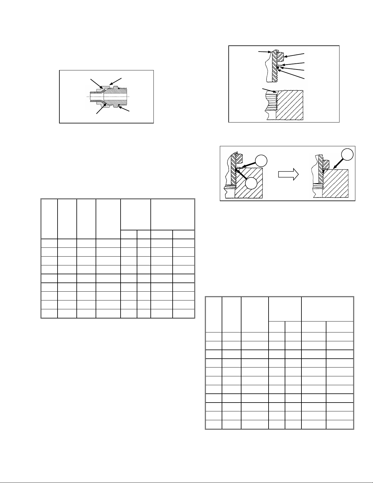
D. HYDRAULIC FITTINGS................................................................................................................ 7
ENGLISH/METRIC EQUIVALENTS.......................................................................................................................... 8
DEFINITIONS ............................................................................................................................................................ 8
STEP 1. UNLOAD HEADER............................................................................................................................. 9
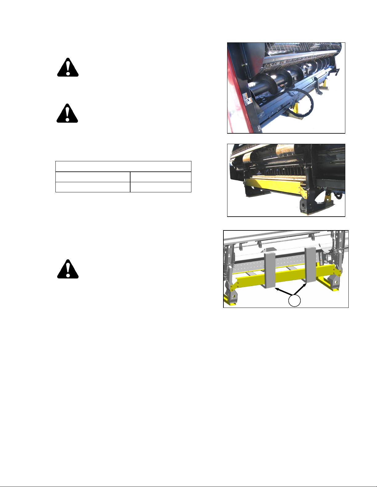
STEP 2. REMOVE UNDERSIDE SHIPPING STAND..................................................................................... 10
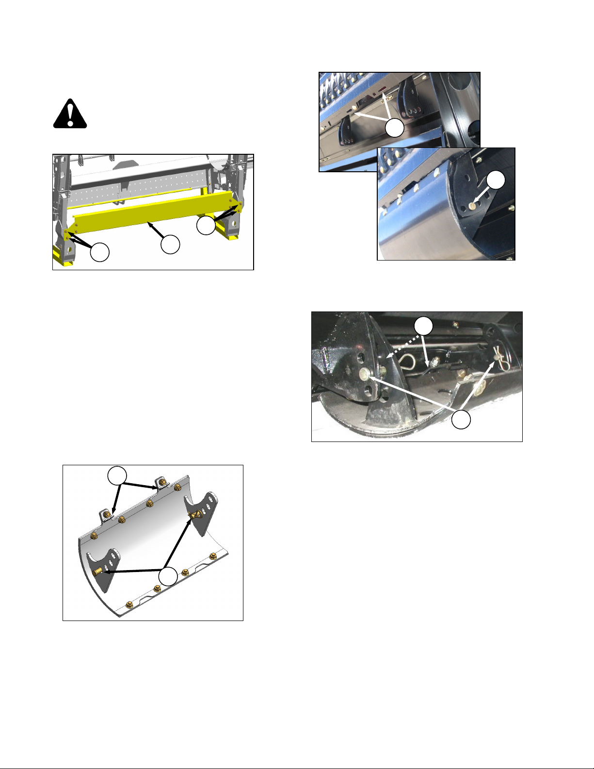
STEP 3. INSTALL ADDITIONAL SKID SHOES............................................................................................. 10
STEP 4. INSTALL GAUGE ROLLERS........................................................................................................... 11
STEP 5. LOWER HEADER............................................................................................................................. 12
STEP 6. REMOVE SHIPPING STANDS......................................................................................................... 13
STEP 7. INSTALL TALL CROP DIVIDER ...................................................................................................... 14
STEP 8. ADJUST LEAN BAR ........................................................................................................................ 15
STEP 9. ADJUST PAN EXTENSIONS - GRASS SEED SPECIAL ............................................................... 15
STEP 10. ADJUST LIGHTS.............................................................................................................................. 15
STEP 11. ASSEMBLE FORMING SHIELD ...................................................................................................... 16
STEP 12. INSTALL FORMING SHIELD........................................................................................................... 17
STEP 13. ATTACH HEADER TO WINDROWER............................................................................................. 18
STEP 14. MODIFY HYDRAULICS.................................................................................................................... 21
A. A30-S AND A30-D ...................................................................................................................... 21
B. A40-D.......................................................................................................................................... 21
I. M100 ...................................................................................................................................... 21
II. M150 ...................................................................................................................................... 23
III. M200 ...................................................................................................................................... 24
IV. M205 ...................................................................................................................................... 26
STEP 15. CONFIGURE REVERSER VALVE JUMPER HOSE ....................................................................... 27
STEP 16. ATTACH HYDRAULICS ................................................................................................................... 29
A. A30-S, A30-D.............................................................................................................................. 29
I. M100, M150, M200, M205 ..................................................................................................... 29
B. A40-D.......................................................................................................................................... 31
I. M100 ...................................................................................................................................... 33
II. M150 ...................................................................................................................................... 33
III. M200 ...................................................................................................................................... 33
IV. M205 ...................................................................................................................................... 33
STEP 17. CONFIGURE HOSE ROUTING........................................................................................................ 34
STEP 18. REPOSITION WOBBLE BOX BREATHER ..................................................................................... 34
STEP 19. LUBRICATE THE HEADER ............................................................................................................. 35
STEP 20. PERFORM PRE-DELIVERY CHECKS ............................................................................................ 44
A. DRIVE BELTS AND DRIVE CHAINS ......................................................................................... 44
I. A30-S SINGLE KNIFE ........................................................................................................... 44
II. A30-D DOUBLE KNIFE ......................................................................................................... 44
III. A40-D DOUBLE KNIFE ......................................................................................................... 45
B. AUGER STRIPPER BAR CLEARANCE .................................................................................... 46
C. REEL TINE TO HEADER PAN CLEARANCE............................................................................ 46
D. HEADER FLOTATION................................................................................................................ 47
E. HEADER LEVELLING ................................................................................................................ 48
F. CONDITIONER ROLLS.............................................................................................................. 49
G. SKID SHOES/GAUGE ROLLERS .............................................................................................. 50
H. LIGHTS ....................................................................................................................................... 50
I. RUN-UP THE HEADER.............................................................................................................. 51
J. KNIFE ......................................................................................................................................... 52
K. MANUALS................................................................................................................................... 52

Form 169078 Revision C
4
GENERAL SAFETY
CAUTION
The following are general farm safety
precautions that should be part of your
operating procedure for all types of machinery.
•Protect yourself.
•When assembling, operating and servicing
machinery, wear all the protective clothing
and personal safety devices that COULD be
necessary for the job at hand. Don't take
chances.
•You may need:
oa hard hat.
oprotective shoes with slip resistant soles.
oprotective glasses or goggles.
oheavy gloves.
owet weather gear.
orespirator or filter mask.
ohearing protection. Be aware that
prolonged exposure to loud noise can
cause impairment or loss of hearing.
Wearing a suitable hearing protective
device such as ear muffs (A) or ear plugs
(B) protects against objectionable or loud
noises.
•Provide a first-aid kit for use in case of
emergencies.
•Keep a fire extinguisher on the machine. Be
sure the extinguisher is properly maintained
and be familiar with its proper use.
•Keep young children away from machinery at
all times.
•Be aware that accidents often happen when
the operator is tired or in a hurry to get
finished. Take the time to consider the safest
way. Never ignore warning
signs of fatigue.
•Wear close-fitting clothing
and cover long hair. Never
wear dangling items such as
scarves or bracelets.
•Keep hands, feet, clothing
and hair away from moving
parts. Never attempt to clear obstructions or
objects from a machine while the engine is
running.
•Keep all shields in place. Never alter or
remove safety equipment. Make sure
driveline guards can rotate independently of
the shaft, and can telescope freely.
•Use only service and repair parts made or
approved by the equipment manufacturer.
Substituted parts may not meet strength,
design, or safety requirements.
•Do not modify the machine. Unauthorized
modifications may impair the function and/or
safety and affect machine life.
(continued next page)
A
B

Form 169078 Revision C
5
•Stop engine, and remove key from ignition
before leaving operator's seat for any
reason. A child or even a pet could engage
an idling machine.
•Keep the area used for
servicing machinery clean
and dry. Wet or oily floors
are slippery. Wet spots can
be dangerous when
working with electrical
equipment. Be sure all
electrical outlets and tools
are properly grounded.
•Use adequate light for the
job at hand.
•Keep machinery clean. Do
not allow oil or grease to accumulate on
service platforms, ladders or controls. Clean
machines before storage.
•Never use gasoline, naphtha or any volatile
material for cleaning purposes. These
materials may be toxic and/or flammable.
•When storing machinery, cover sharp or
extending components to prevent injury from
accidental contact.

Form 169078 Revision C
6
RECOMMENDED TORQUES
A. GENERAL
The tables shown below give correct torque
values for various bolts and capscrews.
•Tighten all bolts to the torques specified in
chart unless otherwise noted throughout this
manual.
•Check tightness of bolts periodically, using
bolt torque chart as a guide.
•Replace hardware with the same strength
bolt.
•Torque figures are valid for non-greased or
non-oiled threads and heads unless
otherwise specified. Do not grease or oil
bolts or capscrews unless specified in this
manual.
•When using locking elements, increase
torque values by 5%.
B. SAE BOLTS
BOLT
DIA. "A"
in.
NC BOLT TORQUE*
SAE 5 SAE 8
lbf∙ft N·m lbf∙ft N·m
1/4 9 12 11 15
5/16 18 24 25 34
3/8 32 43 41 56
7/16 50 68 70 95
1/2 75 102 105 142
9/16 110 149 149 202
5/8 150 203 200 271
3/4 265 359 365 495
7/8 420 569 600 813
1 640 867 890 1205
* Torque categories for bolts and capscrews are identified by
their head markings.
C. METRIC BOLTS
BOLT
DIA. "A"
STD COARSE BOLT TORQUE*
8.8 10.9
lbf∙ft N·m lbf∙ft N·m
M3 0.4 0.5 1.3 1.8
M4 2.2 3 3.3 4.5
M5 4 6 7 9
M6 7 10 11 15
M8 18 25 26 35
M10 37 50 52 70
M12 66 90 92 125
M14 103 140 148 200
M16 166 225 229 310
M20 321 435 450 610
M24 553 750 774 1050
M30 1103 1495 1550 2100
M36 1917 2600 2710 3675
* Torque categories for bolts and capscrews are identified by
their head markings.
SAE-5
SAE-8

Form 169078 Revision C
7
D. HYDRAULIC FITTINGS
FLARE TYPE
a. Check flare and flare seat for defects that might
cause leakage.
b. Align tube with fitting before tightening.
c. Lubricate connection, and hand-tighten swivel
nut until snug.
d. To prevent twisting the tube(s), use two
wrenches. Place one wrench on the connector
body, and with the second, tighten the swivel nut
to the torque shown.
SAE
NO.
TUBE
SIZE
O.D.
(in.)
THD
SIZE
(in.)
NUT
SIZE
ACROSS
FLATS
(in.)
TORQUE
VALUE*
RECOMMENDED
TURNS TO
TIGHTEN
(AFTER FINGER
TIGHTENING)
ft·lbf
N·m
Flats
Turns
3 3/16 3/8 7/16 6 8 1 1/6
4 1/4 7/16 9/16 9 12 1 1/6
5 5/16 1/2 5/8 12 16 1 1/6
6 3/8 9/16 11/16 18 24 1 1/6
8 1/2
3/4
7/8 34 46 1 1/6
10 5/8 7/8 1 46 62 1 1/6
12 3/4 1-1/16 1-1/4 75 102 3/4 1/8
14 7/8 1-3/16 1-3/8 90 122 3/4 1/8
16 1 1-5/16 1-1/2 105 142 3/4 1/8
* The torque values shown are based on lubricated connections
as in re-assembly.
O-RING TYPE
a. Inspect O-ring and seat for dirt or obvious
defects.
b. On angle fittings, back off the lock nut until
washer (A) “bottoms out” at top of groove (B) in
fitting.
c. Hand-tighten fitting until back up washer (A) or
washer face (if straight fitting) bottoms on part
face (C), and O-ring is seated.
d. Position angle fittings by unscrewing no more
than one turn.
e. Tighten straight fittings to torque shown.
f. Tighten angle fittings to torque shown in the
following table, while holding body of fitting with
a wrench.
SAE
NO.
THD
SIZE
(in.)
NUT SIZE
ACROSS
FLATS
(in.)
TORQUE
VALUE*
RECOMMENDED
TURNS TO TIGHTEN
(AFTER FINGER
TIGHTENING)
ft·lbf N·m Flats Turns
3 3/8 1/2 6 8 2 1/3
4 7/16 9/16 9 12 2 1/3
5 1/2 5/8 12 16 2 1/3
6 9/16 11/16 18 24 2 1/3
8 3/4 7/8 34 46 2 1/3
10 7/8 1 46 62 1-1/2 1/4
12 1-1/16 1-1/4 75 102 1 1/6
14 1-3/16 1-3/8 90 122 1 1/6
16 1-5/16 1-1/2 105 142 3/4 1/8
20 1-5/8 1-7/8 140 190 3/4 1/8
24 1-7/8 2-1/8 160 217 1/2 1/12
* The torque values shown are based on lubricated connections
as in re-assembly.
FLARE
FLARESEAT
BODY
NUT
LOCKNUT
WASHER
O-RING
GROOVE
FITTING
SEAT
A
B
C

Form 169078 Revision C
8
ENGLISH/METRIC EQUIVALENTS
QUANTITY INCH-POUND UNITS FACTOR SI UNITS (METRIC)
UNIT NAME ABBR. UNIT NAME ABBR.
Area acres acres x 0.4047 = hectares ha
Flow US gallons per minute gpm x 3.7854 = liters per minute L/min
Force pounds force lbf x 4.4482 = Newtons N
Length
inch in. x 25.4 = millimeters mm
foot ft x 0.305 = meters m
Power horsepower hp x 0.7457 = kilowatts kW
Pressure pounds per square inch psi
x 6.8948 = kilopascals kPa
x .00689 = megapascals MPa
Torque
pound feet or foot pounds lbf∙ft or ft∙lbf x 1.3558 = newton meters N·m
pound inches or inch pounds lbf∙in. or in∙lbf x 0.1129 = newton meters N·m
Temperature degrees Fahrenheit ˚F (˚F - 32) x 0.56 = Celsius ˚C
Velocity
feet per minute ft/min x 0.3048 = meters per minute m/min
feet per second ft/s x 0.3048 = meters per second m/s
miles per hour mph x 1.6063 = kilometers per hour km/h
Volume
US gallons US gal. x 3.7854 = liters L
ounces oz. x 29.5735 = milliliters ml
cubic inches in.3x 16.3871 = cubic centimeters cm3or cc
Weight pounds lb x 0.4536 = kilograms kg
DEFINITIONS
TERM DEFINITION
API American Petroleum Institute
APT Articulating Power Tongue
ASTM American Society Of Testing And Materials
Header The removable portion of a harvesting machine (windrower, combine, mower) that cuts
and conveys crops to a delivery opening. Includes sickle, reel and conveying systems.
PTO Power Take-Off
rpm Revolutions Per Minute
SAE Society Of Automotive Engineers
Windrower A piece of harvesting equipment used to cut and lay crop in windrows or swaths.
Windrower Tractor The propelling portion of a self-propelled windrower, including the Operator’s station.
Wobble Box
An enclosed system that translates rotating motion from the machine drive into
reciprocating motion to the sickle.

UNLOADING AND ASSEMBLY
Form 169078 Revision C
9
STEP 1. UNLOAD HEADER
CAUTION
To avoid injury to bystanders from being
struck by machinery, do not allow persons to
stand in unloading area.
CAUTION
Equipment used for unloading must meet or
exceed the requirements specified below.
Using inadequate equipment may result in
chain breakage, vehicle tipping or machine
damage.
LIFTING VEHICLE
Minimum Capacity * 8000 lb (3630 kg)
Minimum Fork Length 78 in (1981 mm)
* At 48 inches (1220 mm) from back end of
forks.
IMPORTANT
Forklifts are normally rated for a load
located 24 inches (610 mm) ahead of
back end of the forks. To obtain the
forklift capacity at 48 inches (1220 mm),
check with your forklift distributor.
WARNING
Be sure forks are secure before moving away
from load. Stand clear when lifting.
IMPORTANT
Do not unload using lean bar for lifting.
Chain hook slots in lean bar are only for
laying the machine over into working
position after it is on the ground.
NOTE
Take care not to bend parts on back tube.
a. Approach header from either its "topside" or
"underside", and slide forks (A) in underneath
lifting framework as far as possible.
NOTE
When possible, approach from the
underside to minimize potential for
scratching the unit.
b. Remove hauler's tie down straps and chains.
c. Raise header off deck.
IMPORTANT
Take care not to contact the other
machine if load is two-wide.
d. Back up until unit clears trailer, and slowly lower
to 6 inches (150 mm) from ground.
e. Take to storage or set-up area.
f. Set machine down securely on level ground.
g. Check for shipping damage and missing parts.
A
TOPSIDE
UNDERSIDE

UNLOADING AND ASSEMBLY
Form 169078 Revision C
10
STEP 2. REMOVE UNDERSIDE
SHIPPING STAND
CAUTION
Keep feet clear when removing final bolts.
a. Remove four bolts (A), and remove shipping
stand (B). Discard stand and hardware.
STEP 3. INSTALL ADDITIONAL
SKID SHOES
If kit is not supplied, proceed to STEP 4.
INSTALL GAUGE ROLLERS.
Otherwise proceed as follows:
NOTE
This kit may be installed later in the
header assembly sequence, but it may be
easier prior to laying the header down.
a. Unpack skid shoe bundle.
b. Remove two clevis pins (C) from each skid
shoe.
c. Remove nuts, bolts, and clips (D) from skid
shoe.
d. Insert tabs on skid shoe into slots (E) on
cutterbar at inboard mounting locations on
frame, and secure with clevis pin (C).
e. Attach clips (D) with bolts and nuts removed at
step c. to secure skid shoe to cutterbar.
NOTE
Use a socket and ratchet wrench to
access the nuts.
f. Remove clevis pin (C), and adjust skid shoe to
desired height. Re-install two clevis pins (C)
and secure with lynch pins.
g. Repeat above steps for opposite side. Set both
skid shoes to same position.
A
A
B
D
C
E
C
D
C

UNLOADING AND ASSEMBLY
Form 169078 Revision C
11
STEP 4. INSTALL GAUGE
ROLLERS
If kit not supplied proceed to STEP 5. LOWER
HEADER. Otherwise install kit as follows:
NOTE
This kit may be installed later in the
header assembly sequence but it may be
easier prior to laying the header down.
a. Unpack gauge roller bundle.
b. Remove two locking pins (A) from each
assembly.
c. Remove nuts, bolts, and clips (B) from
assembly.
d. Insert tabs on roller assembly into slots (C) on
cutterbar at outboard mounting locations on
frame, and secure to support bracket with
locking pin (A) at “lowest position”.
e. Attach clips (B) with bolts and nuts removed at
step c. to secure roller assembly to cutterbar.
f. Tighten nuts.
NOTE
Use a socket and ratchet wrench to
access the nuts.
g. Remove locking pin (A), and adjust rollers to
desired height. Re-install both locking pins (A).
h. Ensure that nut (D) on each pin registers in
adjacent hole in support bracket.
i. Secure pins with hairpins (E).
j. Repeat above steps for opposite side. Set both
gauge rollers to same position.
B
A
C
B
A
A
E
D

UNLOADING AND ASSEMBLY
Form 169078 Revision C
12
STEP 5. LOWER HEADER
a. Attach either a spreader bar or chain to forks.
CAUTION
Ensure spreader bar or chain is secured to
the forks so that it cannot slide off the
forks or towards the mast as the header is
lowered to the ground.
b. Drive lifting vehicle to approach header from its
"underside".
c. Attach chain hooks to lean bar at slots as
shown.
IMPORTANT
See "Chain Requirements" in this section
for minimum chain specifications. Also,
chain length must be sufficient to provide
a minimum 4 feet (1.2 m) vertical chain
height.
CHAIN TYPE OVERHEAD LIFTING
QUALITY (1/2 INCH)
MINIMUM
WORKING LOAD
5000 lb
(2270 kg)
CAUTION
Stand clear when lowering, as machine may
swing.
NOTE
Do not lift at lean bar when unloading from
trailer. This procedure is only for laying the
machine over into working position.
d. Raise forks until lift chains are fully tensioned.
e. Back up SLOWLY, while simultaneously
lowering machine so that cutterbar skid shoes
rest on blocks (A).
f. Remove chain hooks from lean bar.
g. Attach chain to center link anchor (B) on frame
tube, and raise rear of header approximately
12 inches (305 mm) off ground.
(continued next page)
A
A
LOWERING HEADER WITH FORKLIFT
LOWERING HEADER WITH CRANE
48 in. (1.2 m)
MINIMUM
B

UNLOADING AND ASSEMBLY
Form 169078 Revision C
13
h. Remove lynch pin from pin (C) in header stand
at right side of header.
i. Hold stand (D) and remove pin (C).
j. Invert stand (D), and re-install on header leg in
upper hole location with pin (C). Secure pin with
lynch pin.
NOTE
In soft conditions use a wooden block
under the stand.
k. Lower header onto stand (D).
STEP 6. REMOVE SHIPPING
STANDS
a. Remove two bolts (E) from shipping stand (F).
b. Remove hairpin from pin (G).
c. Hold shipping stand (F), remove pin (G), and
remove stand. Discard stand and hardware.
d. Repeat above steps for opposite shipping stand.
e. Remove four bolts (H), and remove angle (J).
Discard angle and hardware.
C
D
C
D
F
G
E
J
H

UNLOADING AND ASSEMBLY
Form 169078 Revision C
14
STEP 7. INSTALL TALL CROP
DIVIDER
If kit is not supplied, proceed to STEP 8. ADJUST
LEAN BAR. Otherwise proceed as follows:
a. Remove hardware on both sides of lean bar,
and remove lean bar.
b. Attach extensions (C) to lean bar with four bolts
(D) and nuts provided.
c. Re-attach lean bar to header with existing
hardware at desired location.Tighten bolts.
d. Attach LH divider assembly (E) to LH end of
lean bar with two bolts (F) and nuts provided.
The divider may be positioned as shown, or
using the optional mounting hole (G).
e. Install U-bolt (H), and tighten all bolts.
f. Repeat for RH divider.
C
D
H
E
F
G

UNLOADING AND ASSEMBLY
Form 169078 Revision C
15
STEP 8. ADJUST LEAN BAR
a. Lean bar is fully retracted for shipping. Remove
hardware on both sides, and install lean bar in
field position at position suitable for crop
(normally 2/3 of the crop height).
b. Proceed to STEP 10. ADJUST LIGHTS. If this
is a Grass Seed Header, proceed as follows:
STEP 9. ADJUST PAN
EXTENSIONS - GRASS
SEED SPECIAL
The grass seed header auger pan extensions
are factory installed for the widest delivery
opening. Adjust as follows:
a. Remove two bolts (A), and loosen bolt (B).
b. Slide pan extensions (C) and swath forming rods
“inboard” to desired position, and align holes.
c. Re-install two bolts (A). Tighten bolts (A) and
(B).
d. Repeat for opposite pan extension.
STEP 10. ADJUST LIGHTS
a. Position amber light supports perpendicular to
header.
b. Check that pivot bolt is tight enough to hold light
support in upright position, yet still allow light to
pivot out of the way of obstructions.
NOTE
Do not over-tighten mounting hardware.
c. Ensure base of light housings and bolted
connections on light supports provide proper
electrical grounding.
d. Amber reflector (D) should face direction of
travel. If required, remove bolts (E), flip reflector
assembly, and re-install bolts.
A
B
C
WIDE
A
B
C
NARROW
D
E

UNLOADING AND ASSEMBLY
Form 169078 Revision C
16
STEP 11. ASSEMBLE FORMING
SHIELD
a. Unpack and remove shipping material.
b. Lay cover (A) upside down on a flat surface.
c. Remove bolts (B) from side deflectors (C).
d. Assemble side deflectors (C) to cover (A) with
bolts (B), jam-nut (D), washer (E), and nut (F)
from previous step.
e. Tighten flange nut (F) enough to hold deflectors
(C) in position, but still allow deflectors to move.
f. Tighten jam nut (D) against cover while holding
bolt (B).
g. Remove lynch pin (G) from adjuster rod (H) and
locate rod in hole in side deflector (C). Secure
with lynch pin (G).
h. Repeat for other deflector.
i. Invert forming shield to installation position as
shown.
A
G
H
C
B
C
B
F
D
E
C
C

UNLOADING AND ASSEMBLY
Form 169078 Revision C
17
STEP 12. INSTALL FORMING
SHIELD
a. Remove the header from the windrower (if
attached) for ease of installation of the forming
shield.
NOTE
Do not install the two triangular shaped
plates.
b. Install bolt (A) with spacer (B), and nut on each
leg in the upper hole. Hardware is supplied with
forming shield kit.
c. Remove the two clevis pins (C) from “forward
end” of forming shield.
d. Position forming shield under the windrower
frame.
e. Locate forming shield onto bolts (A) in
windrower legs, and secure with clevis pins (C)
and lynch pin.
f. Lift the aft end of the forming shield, and attach
straps (D) to pins (E) on windrower frame.
Install washer and hairpin to secure strap. Use
the middle hole, and adjust height to suit the
crop.
(continued next page)
A
B
C
C
A
D
E

UNLOADING AND ASSEMBLY
Form 169078 Revision C
18
g. Set forming shield side deflectors to desired
width by repositioning adjuster bars (F). Use
same hole location on both sides.
•Position deflectors at the narrowest
setting for a narrow windrow (silage for
example).
•Position deflectors at the widest position
for a wide window.
NOTE
Refer to the Operator’s Manual or Quick
Card for additional information on
adjusting the forming shield.
h. Adjust fluffer shield (G) to middle position.
Loosen handles (H) if required.
STEP 13. ATTACH HEADER TO
WINDROWER
a. Remove pins (A) from left and right header
boots.
IMPORTANT
To prevent damage to the lift system when
lowering header lift linkages without a
header or weight box attached to
windrower, ensure that float engagement
pin is installed in storage location (C), and
not installed at hole location (D).
CAUTION
Check to be sure all bystanders have cleared
the area.
b. Start the engine, and activate HEADER DOWN
button on the GSL to fully retract header lift
cylinders.
(continued next page)
HEADER UP
HEADER TILT UP
HEADER DOWN
HEADER
TILT DOWN
B
A
BOTH SIDES
G
H
F
D
C

UNLOADING AND ASSEMBLY
Form 169078 Revision C
19
c. Slowly drive windrower forward so that feet (E)
enter boots (B) on the header. Continue to drive
slowly forward until feet engage the boots, and
header nudges forward.
d. Connect center link as follows:
MECHANICAL LINK - M100, M150
DANGER
Stop engine, and remove key from ignition
before leaving operator's seat for any
reason. A child or even a pet could engage
an idling machine.
1. Stop engine, and remove key.
2. Loosen nut (F), and rotate barrel (G) to
adjust length so that other end “lines up”
with header bracket.
3. Install pin (H), and secure with cotter pins.
4. Adjust link to required length for proper
header angle by rotating barrel (G). Tighten
nut (F) against barrel. A slight tap with a
hammer is sufficient.
5. Proceed to step e.
HYDRAULIC LINK WITHOUT SELF-ALIGNMENT
KIT - M200 STD, M150 AND M100 OPTIONAL
1. Activate HEADER TILT cylinder switches on
GSL to extend or retract center link cylinder
so that the hook lines up with the header
attachment pin.
2. Stop engine, and remove key.
3. Re-locate the pin at the frame linkage as
required to position the hook over the
header pin.
4. Push “down” on rod end of link cylinder until
hook engages pin on header, and is locked.
5. Check that center link is locked onto header
by pulling “upward” on rod end of cylinder.
6. Proceed to step e.
(continued next page)
B
E
G
F
H
HEADER TILT UP
HEADER
TILT DOWN
REEL UP
REEL DOWN

UNLOADING AND ASSEMBLY
Form 169078 Revision C
20
HYDRAULIC LINK WITH OPTIONAL SELF-
ALIGNMENT KIT - M205 STD, M200, M150 AND
M100 OPTIONAL
1. Adjust the position of the center link cylinder
with the REEL UP and REEL DOWN
switches, and HEADER TILT switches on
the GSL to position the hook above the
header attachment pin.
2. Lower the center link onto the header with
REEL UP switch, until it locks into position
(handle is “down”).
e. Raise the header fully with the HEADER UP
switch on the GSL. Stop engine, and remove
key.
DANGER
To avoid bodily injury from fall of raised
header, always engage header lift cylinder
stops when working on or around raised
header.
f. Pull lever (A), and rotate “toward” header to
release and lower cylinder stop (B) onto
cylinder. Repeat for both lift cylinders.
g. Install pin (C) through each boot and foot, and
secure with hairpin.
IMPORTANT
Ensure pin (C) is fully inserted, and hairpin
is installed behind bracket.
(continued next page)
C
HEADER UP
HEADER TILT UP
HEADER DOWN
HEADER
TILT DOWN
B
A
Other manuals for A30-S
4
This manual suits for next models
2
Table of contents
Other MacDon Farm Equipment manuals

MacDon
MacDon R113 User manual

MacDon
MacDon R113 User manual

MacDon
MacDon M155 User manual

MacDon
MacDon M1240 User manual

MacDon
MacDon M1 Series User manual

MacDon
MacDon 3020 User manual

MacDon
MacDon A40-D User manual

MacDon
MacDon Swath Compressor Guide

MacDon
MacDon DWA Guide

MacDon
MacDon R1 Series User manual