manuals.online logo
Brands
  1. Home
  2. •
  3. Brands
  4. •
  5. Horstmann
  6. •
  7. Plumbing Product
  8. •
  9. Horstmann Z322XL Installation and operation manual

Horstmann Z322XL Installation and operation manual

LEAFLET No P80955
ISSUE 2
Page 4
Email: [email protected]k
Website: www.horstmann.co.uk
The Z322XL mid-position valve has been designed to control
the water circulation in fully pumped systems, which employs
a single pump for both Hot water and Central heating circuits,
by diverting the flow to either circuit or both simultaneously
using a single valve.
Horstmann Controls Limited
Bristol
BS4 1UP
t:0117 9788 773 - f:0117 9788 701
APPLICATION
Motor supply voltage: 230V AC, 50Hz
Power consumption:<6W
Lead supplied:1 meter 4 core cable. Industry standard colours used
No earth connection required as unit is double insulated
Operating flow temperature:-5
o
C to 88
o
C
Switch rating:3Amps
Maximum ambient temperature:50
o
C
SPECIFICATION
Maximum static pressure:8.6 Bar
Maximum differential pressure: 0.5 Bar
Pipe fitting size:22mm compression
Actuator:Maximum time to power
open - 20 seconds
Maximum time to spring
close - 10 seconds
Override lever:For manual operating to
mid-position for system draining or filling.
During normal operation, the lever must be
in the auto position.
(See diagram opposite).
To check whether the valve is operating correctly, carry out the following checks after the system is
filled and vented. Ensure that the override lever is back in the Auto position and the insert guide is
removed.
HOTWATERONLY.
Set the room thermostat to minimum or turn the CH off at the programmer.
Set the cylinder thermostat to maximum and turn the HW on at the programmer.
The valve should close Port A. The boiler should fire, pump run and the pipe on the Port B side should
get hot.
CENTRALHEATINGONLY.
Set the cylinder thermostat to minimum or turn the HW off at the programmer.
Set the room thermostat to maximum and turn the CH on at the programmer.
The valve should close Port B. The boiler should fire, pump run and the pipe on the Port A side should
get hot.
HOTWATERANDCENTRALHEATING.
Set the room and cylinder thermostat to maximum and turn the HW and CH on at the programmer.
The valve should be in the mid-position. The boiler should fire, pump run and the pipes on both Port A
side and Port B should get hot.
Reset both thermostats and the programmer to their normal settings.
Please notethe above assumes that both programmer and thermostats are being used. If this is not
the case, ignore the action described for the item not fitted.
SPARES
The actuator and body for the Z322XL mid-position valve can be purchased separately as spares or as
replacement parts(see page 1).
The Z322XL consists of a 3 port valve body (Ref.B322XL) to
which a self-contained actuator (Ref.A322XL) is attached.Page 1
INSTALLATION AND CONNECTION SHOULD ONLY BE CARRIED OUT BY A SUITABLY QUALIFIED PERSON
AND IN ACCORDANCE WITH THE CURRENT EDITION OF THE IEE WIRING REGULATIONS.
A CLASS ‘A’ SWITCH (HAVING CONTACT SEPARATION OF AT LEAST 3MM IN ALL POLES) MUST BE
INCORPORATED IN THE FIXED WIRING AS A MEANS OF DISCONNECTING THE SUPPLY, NORMALLY AT THE
CONSUMER UNIT. THE SYSTEM MUST BE APPROPRIATELY FUSED.
WARNING:ISOLATE MAINS SUPPLY BEFORE COMMENCING INSTALLATION
B322XL - BODY
A322XL - ACTUATOR
COMMISSIONING
Page 2
OPERATION
Valve position - In the event that mains
power is disconnected the valve
automatically spring-returns to the Hot
water only position.
Position of valve during the various
operation:
HW only - Port A closed
HW & CH - Valve in position AB (Middle)
CH only - Port B closed
The Valve operates both boiler and
pump when either Heating or Hot water
is required.
Fit the valve body using the
22mm compression fittings
provided with the flow from
the boiler to AB, the radiator
circuit to Port A, and the Hot
water cylinder to Port B.
Tighten the compression nuts
sufficiently to make a
watertight seal, only gripping
the valve by its body.
Take care not to over tighten.
INSTALLATION
POSITIONING OF VALVE
On new installations ensure that the Z322XL valve is fitted on the flow from the boiler only. Also check
that the actuator head is NOTbelow the horizontal level of the pipework and that neither the open
vent nor the cold feed are isolated. This will ensure system and product safety at all times.
Remember to make allowances for working, maintenance and replacement.
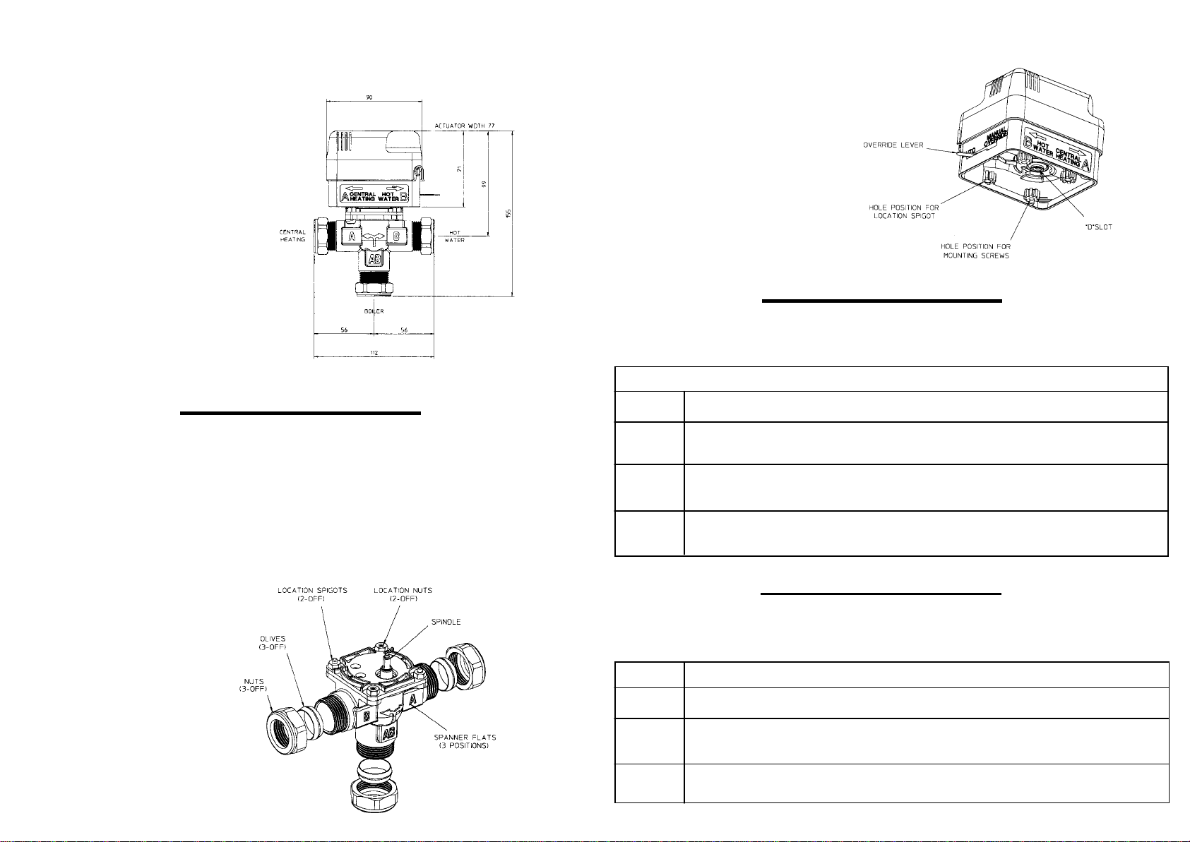
FITTING OF VALVE BODY TO PIPEWORK
FIT ACTUATOR TO VALVE BODY
Position the actuator on the valve body
lining up the valve spindle with the ‘D’
shape slot. A yellow guide strip has been
inserted behind the Override lever to
assist installation,please remove the
guide once the actuator installation is
complete and before the system is used.
The actuator guide holes should line up
with the spigots on the valve body.
Fix with the screws provided and tighten
lightly. The override lever should now be
on the Port B side.
WIRING CONNECTIONS- STANDARD INSTALLATION
The 4 core cable fitted to the actuator can now be connected to the system following the simple
colour-coded guide below.
Wire ColourSystem Connection
BlueAny Neutral supply.
Orange‘Call’ terminal of Cylinder Stat if fitted, otherwise the ‘HW ON’ terminal of
the programmer - Also link to Pump/Boiler live.
White‘Call’ terminal of room Stat if fitted, otherwise the ‘CHON’ terminal of
programmer.
Grey‘Stat’ terminal of Cylinder Stat if fitted, otherwise the ‘HW OFF’ terminal of
the programmer.
No earth connection is required. Ensure all connections are good and the screw secure. A torque of
0.75Nm is recommended for fixing the wires in place.
Set the override lever to manual. Fill, test and thoroughly flush the system (see diagram and
instruction under the Specification section located on page 4 of this guide).
USING A ZONEPLUS Z322XL AS A DIVERTER VALVE
The following connections will enable the Z322XL to act as a diverter valve, giving priority to the
Central heating.
Wire ColourSystem Connection
BlueAny Neutral supply.
Orange‘Call’ terminal of Cylinder Stat if fitted, otherwise the ‘HW ON’ terminal of
the programmer - Also link to Pump/Boiler live.
White+Grey‘Call’ terminal of room Stat if fitted, otherwise the ‘CHON’ terminal of
programmer.
Page 3

Other Horstmann Plumbing Product manuals

Horstmann ZonePlus F328m Installation and operation manual

Horstmann

Horstmann ZonePlus F328m Installation and operation manual

Horstmann ZonePlus F228m Installation and operation manual

Horstmann

Horstmann ZonePlus F228m Installation and operation manual

Horstmann ZonePlus Z222 Installation and operation manual

Horstmann

Horstmann ZonePlus Z222 Installation and operation manual

Popular Plumbing Product manuals by other brands

Pfister Winfield RT6-5WF Quick installation guide

Pfister

Pfister Winfield RT6-5WF Quick installation guide

Fortis Scala 8471100 installation instructions

Fortis

Fortis Scala 8471100 installation instructions

Spectrum Brands Pfister Avalon LG49-CB1 Quick installation guide

Spectrum Brands

Spectrum Brands Pfister Avalon LG49-CB1 Quick installation guide

Delta TALBOTT 35960LF quick start guide

Delta

Delta TALBOTT 35960LF quick start guide

Dreamline DL-6150-04 installation instructions

Dreamline

Dreamline DL-6150-04 installation instructions

glass 1989 TRIPTI Installation, operation & maintenance manual

glass 1989

glass 1989 TRIPTI Installation, operation & maintenance manual

Clou Flush 3 CL/03.40030 installation instructions

Clou

Clou Flush 3 CL/03.40030 installation instructions

Grohe LADYLUX3 30 313 manual

Grohe

Grohe LADYLUX3 30 313 manual

KWC ONO touch light PRO 12.652.011.000 Installation and service instructions

KWC

KWC ONO touch light PRO 12.652.011.000 Installation and service instructions

Sterling Bar Faucets 26290 Specifications

Sterling

Sterling Bar Faucets 26290 Specifications

Moen ioDIGITAL 3384 Installation

Moen

Moen ioDIGITAL 3384 Installation

ESS Easy Drain Multi TAF EDMTAF2000 Installation advice

ESS

ESS Easy Drain Multi TAF EDMTAF2000 Installation advice

Kohler K-13142 Homeowner's guide

Kohler

Kohler K-13142 Homeowner's guide

Rubi KROnos RKR77 Installation

Rubi

Rubi KROnos RKR77 Installation

Sanela SLU 25 Instructions for use

Sanela

Sanela SLU 25 Instructions for use

KWC QBIX/QBIX-ART 11.253.033.006 specification

KWC

KWC QBIX/QBIX-ART 11.253.033.006 specification

PolyJohn HandStand 2 user manual

PolyJohn

PolyJohn HandStand 2 user manual

Graff 7080 installation instructions

Graff

Graff 7080 installation instructions

manuals.online logo
manuals.online logoBrands
  • About & Mission
  • Contact us
  • Privacy Policy
  • Terms and Conditions

Copyright 2025 Manuals.Online. All Rights Reserved.