ZZOONNEEPPLLUUSSFF222288mm//FF222288ee
IINNSSTTAALLLLAATTIIOONNAANNDD
CCOOMMMMIISSSSIIOONNIINNGGIINNSSTTRRUUCCTTIIOONNSS
LEAFLET No P82412
ISSUE 1
PPaaggee44
Website: www.horstmann.co.uk
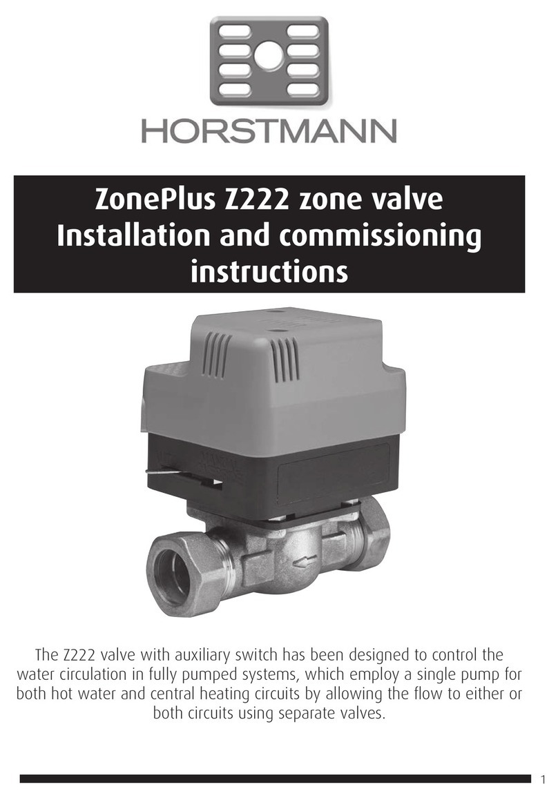
The F228m / F228e valve with auxiliary switch has been designed
to control the water circulation in fully pumped systems, which
employs a single pump for both Hot water and Central heating
circuits, by allowing the flow to either or both circuits using
separate valves.
Horstmann Controls Limited
Bristol
BS4 1UP
t:0117 9788 773 - f:0117 9788 701
MMoottoorrssuuppppllyyvvoollttaaggee::230V AC, 50Hz
PPoowweerrccoonnssuummppttiioonn::<6.5W
LLeeaaddssuupppplliieedd::1 metre 6 core cable. Industry standard colours used
EEaarrtthhccoonnnneeccttiioonnrreeqquuiirreedd..
OOlliivveeSSiizzee::F228m - 28mm (Metric)
F228e- 1 1/4 inch (Imperial)
OOppeerraattiinnggfflloowwtteemmppeerraattuurree::Up to 80oC
SSwwiittcchhrraattiinngg::5 Amps
MMaaxxiimmuummaammbbiieenntttteemmppeerraattuurree::50oC
MMaaxxiimmuummssttaattiiccpprreessssuurree::21 Bar
MMaaxxiimmuummddiiffffeerreennttiiaallpprreessssuurree::2 Bar
PPiippeeffiittttiinnggssiizzee::22mm compression
AAccttuuaattoorr::Maximum time to power open - 20 seconds
Maximum time to spring close - 10 seconds
OOvveerrrriiddeelleevveerr::For manual operating to open valve for system draining or filling.
During normal operation, the lever must be in the auto position.
SPECIFICATION
PPaaggee11
INSTALLATION AND CONNECTION SHOULD ONLY BE CARRIED OUT BY A SUITABLY QUALIFIED
PERSON AND IN ACCORDANCE WITH THE CURRENT EDITION OF THE I.E.E. WIRING
REGULATIONS. A CLASS ‘A’ SWITCH (HAVING CONTACT SEPARATION OF AT LEAST 3MM IN
ALL POLES) MUST BE INCORPORATED IN THE FIXED WIRING AS A MEANS OF DISCONNECTING
THE SUPPLY, NORMALLY AT THE CONSUMER UNIT. THE SYSTEM MUST BE APPROPRIATELY
FUSED.
WWAARRNNIINNGG::IISSOOLLAATTEEMMAAIINNSSSSUUPPPPLLYYBBEEFFOORREECCOOMMMMEENNCCIINNGGIINNSSTTAALLLLAATTIIOONN
COMMISSIONING
To check whether the valve is operating correctly, carry out the following checks after the sys-
tem is filled and vented. Ensure that the override lever is in the Auto position and the insert
guide is removed.
FFOORRGGRRAAVVIITTYYSSYYSSTTEEMMSS::
HHOOTTWWAATTEERROONNLLYY..
Set the room thermostat to minimum or turn the CH off at the programmer.
Set the cylinder thermostat to maximum and turn the HW on at the programmer.
The valve should be open and the boiler only should fire.
CCEENNTTRRAALLHHEEAATTIINNGGOONNLLYY..
Set the cylinder thermostat to minimum or turn the HW off at the programmer.
Set the room thermostat to maximum and turn the CH on at the programmer.
The valve should remain closed but the boiler should fire and the pump should run.
HHOOTTWWAATTEERRAANNDDCCEENNTTRRAALLHHEEAATTIINNGG..
Set the room and cylinder thermostat to maximum and turn the HW and CH on at the
programmer.
The valve should be open. The boiler should fire, pump run and the pipes on the Port B should
get hot.
FFOORRAAFFUULLLLYYPPUUMMPPEEDDSSYYSSTTEEMM::
IIfftthheevvaallvveeiissffiitttteeddoonnaaHHWWcciirrccuuiitt..
Set the cylinder thermostat to maximum or turn the HW on at the programmer. The valve
should open. The boiler should fire, the pump run and the pipe on the Port B side should get
hot.
IIfftthheevvaallvveeiissffiitttteeddoonnaaCCHHcciirrccuuiitt..
Set the room thermostat to maximum or turn the CH on at the programmer. The valve should
open. The boiler should fire, the pump run and the pipe on the Port B side should get hot.
Reset both thermostats and the programmer to their normal settings.
PPlleeaasseennootteethe above assumes that both programmer and thermostats are being used. If this
is not the case, ignore the action described for the item not fitted.


