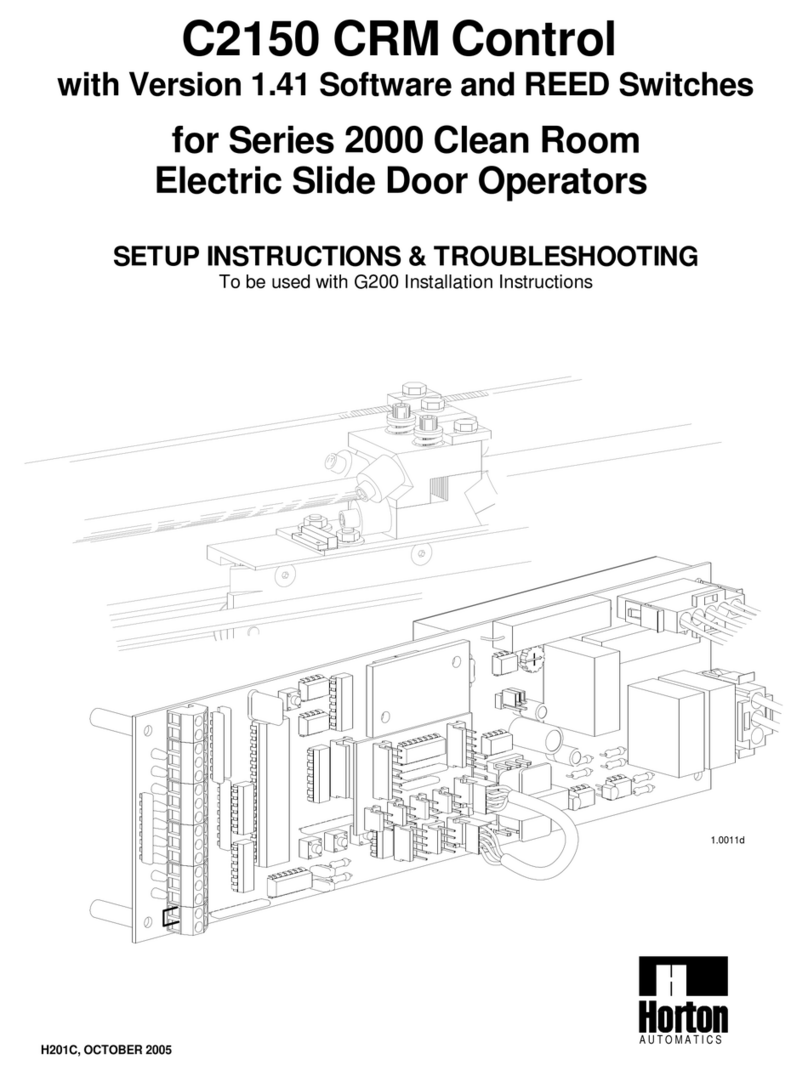
Horton 2000B Series Manual

H202, FEB 2016
A U T O M A T I
C S
2.185d6
C2150 Control
with Version 2 Software and Encoders
for Series 2000B, 2001, 2003 & 2004
Electric Slide Door Operators
SETUP INSTRUCTIONS & TROUBLESHOOTING
To be used with either G2001, G230, G230T, G205, G204 or G20B
Installation Instructions

CONTENTS
SECTIONS
1. Series 2000B, 2001, 2003 & 2004 slide operator instructions………….H202.1
2. C2150 initialization (learn cycle)…………………………………………...H202.2
2. C2150 initialization (learn cycle cont.)…………………………………….H202.3
3. Adjusting parameters (Procedure for changing preset parameters)…..H202.4
4. Adjustable preset parameters (chart of adjustable ranges)…………….H202.4
5. Actuation features…………………………………………………………...H202.5
6. Autolock initialization………………………………………………………..H202.5
7. Setting lock parameters…………………………………………………….H202.6
8. Lock error codes (Trouble shooting guide)……………………………….H202.6
9. Autolock test points………………………………………………………….H202.6
10. Autolock functions…………………………………………………………...H202.6
11. Encoder error codes (Trouble shooting guide)…………………………...H202.7
12. Encoder diagnostics…………………………………………………………H202.7
13. Encoder test points………………………………………………………….H202.7
14. Power failure units (Set up and testing)…………………………………..H202.8
APPENDIX
A. In case of difficulty (Trouble shooting the C2150)………………………..H202.9
B1. Code displays (definitions and trouble shooting guide)………………..H202.10
B2. Code displays (definitions and trouble shooting guide)………………..H202.11
B3. Code displays (definitions and trouble shooting guide - short cuts)….H202.12
C. Motor test…………………………………………………………………….H202.13
D. Terminal CN2 (Description of terminal block connections)…………….H202.13
E. Encoder assembly (circuit board replacement)…………………………..H202.14
F. Bracket attachment (correct attachment of power arms)………………. H202.14
G.Wiring diagram list …………………………………………………………..H202.14
WIRING DIAGRAMS
1.C2150 typical wiring for 2001 & 2003………………………………………H202.15
2.Actuating and control switch connections………………………………….H202.16
3.Typical wiring for beams and switches…………………………………….H202.17
GENERAL STATEMENT
The C2150 is a microprocessor that uses a series of inputs, outputs and custom software to
control a slide door. The inputs are usually supported by LEDs that lets the technician see what
information is coming into the control and the outputs are in the form of display codes, LEDs and
actual control of the motor, autolocks etc. This manual is written for the C2150 control with
Version 2 software which is used in the controls of 2001 and 2003 belt drive operators. The
C2150 control receives its power from a separate power supply (usually a C3925) which provides
+27to +35 VDC to power all of the accessory devices as well as power for the control itself. The
power supply also delivers +100 to +120 VDC to the control which is reduced by a MOSFET (duty
cycle control) and is called into service at variable levels through software and parameter
selection. It is our hope that this manual will guide the experienced technician through the
efficient and safe setup of the C2150 slide door control. Remember that all installations must
comply with ANSI 156.10.

CN 7
TO
AUTOLOCK
FIELD WIRING
OPTION 2
TO
ENCODER
The encoder must be plugged into
CN1 on the control.
To get the operator up and running, check the items outlined below-
Set the reversing sensitivity
fully counter-clockwise.
F2F3
F1
Field wiring options
1. SERIES 2000B, 2001, 2003 & 2004 SLIDE OPERATOR QUICK START INSTRUCTIONS
If the day / night mode is NOT
to be used - there MUST be a
jumper between 15 & 16.
See Sections 5 thru 10 for actuating
features and lock set-up.
With wiring option 1, 2 or 3
The main ground wire must secured using
the green grounding screw.
F2F3
F1
3rd Step
IMPORTANT
2.187d3
The close monitor switch must
be connected to #10 & #11 of CN2.
The switch must trip when the door is
fully closed.
2nd Step
15
16
FIELD WIRING
OPTION 3
Grounding
screw
Grounding
screw
4th Step
Do NOT wire any motion detectors or any other accessories at this time.
Factory pre-wired beams (pins 5,6 & 7) may be left in place.
10th Step
Verify jumpers JB1A & JB1B
are NOT installed on rev. E and
later controls.
C2150 Control with version 2 software (Revision E or later hardware)
2001
switch
11
10
9
8
2003
switch
V-XXXX
CN 2
D1
A toggle switch or jumper must
be present between pins 8 & 9.
Switches are sent loose and field
mounted. Break-outs are wired in
series with the toggle switch .
1st Step
CN 1
CN 4
CN5
Belt drive
(ENC)
9th Step
The motor must be
plugged into connector
CN8
Neutral WHT U.S. - BLU Int.
H202.1
F2
POWER SUPPLY
C3925 for 120VAC-2001 (shown)
C3955 for 120VAC-2003
C3926 for 240VAC-2001
C3956 for 240 VAC-2003
CN 2
Master
fuse
F 1
+27 to +35VDC
& processor
NOTE:
Component arrangement
may vary.
Motor
+100 to +120
VDC
All fuses are
5x20 mm Type "T"
Rated 3.15 amp
F 2
F3
F 3
CN 1
FIELD WIRING
OPTION 1
AC POWER IN
Line (Hot side)
BLK U.S. - BRN Int.
F1
2
31
7th Step
A 5 conductor cable attaches
CN7 to the power supply.
5th Step
BLK
CN 8
GRN / YEL
motor ground
TO
MOTOR
RED
1 2 3 4 5GND
8th Step
Check incoming voltages
from power supply
+120 to +100
VDC from F2 +27 to + 35
VDC from F3
NOTE:
On 2001 & 2003
Metal shields are REQUIRED
by UL
for protection againest
high voltage areas
Do not remove.
Ground GRN U.S. - GRN / YEL Int. (
Connect to grounding screw)
Check that the incoming power
is wired as shown.
6th Step
Shields and chassis
are not shown in this
manual for clarity

-A full learn cycle can not be completed with this security parameter in place.
Consult your supervisor or the factory for authorization and instructions on how to remove
this security parameter.
In version 2.19 and later, the display will show SU
-If SU does not appear, then the control was not
properly reset into the full learn mode (Go back
to step 2)
-If the display flashes nA like an error code,
The nA (no Access) parameter has been
turned on.
-The control will display ONE of the following
lock codes depending the type of lock
connected. (see Section 6)
-The display should "blink" the version number
(as in 2 then 19)
*LOCK CODES
2.188d
O
R
OR
+100
R
+100
+100
R
OR
LOCK
MON
Y
O
LOCK No
Autolock
LOCK
MON
Fail Safe
Autolock
LOCK
MON
O
LOCK
Y
Y
Fail Secure
Autolock
+100
R
R
+100
Y
LOCK
R
Y
O
LOCK
MON
O
LOCK
MON
Y
LOCK
LOCK
THEN
LOCK
MON
+100
LOCK
O
Instruct the control to perform a full learn cycle by:
-Holding down the SET button and the RESET button.
-Release the RESET button.
-Hold the SET button for an additional 5 seconds
then release.
Be sure the toggle circuit is complete and apply
AC power to the unit.
CAUTION: THE DOOR WILL MOVE.
VERSION 2.18 and earlier
2. C2150 INITIALIZATION (learn cycle)
The display should "blink" the version number
(as in 2 then 11) *The display will show the lock
code (see below)
VERSION 2.19 and LATER
3rd Step - Version display
1st Step - Power up
2nd Step - Learn cycle
SET
R
+100
+100
R
LOCK
MON
LOCK
Y
O
Y
THEN
LOCK
MON
+100 LOCK
MON
Y
RO
LOCK
O
LOCK
RESET
H202.2
-The display should indicate FC (for first run - Finding
Close stop) The door should fully close at slow speed.
-In versions later than 2.11, Pd canbeovercomeby
holding the up button untill the door closes.
NOTE: Pressing the wrong button (wrong series) will result in the
operator proceeding in a setup which should yield proper operation,
but the number displayed when accessing ts (total stroke) and other
stroke dependent parameters will be incorrect.
-To approve the selected type push the SET button
-If the door moves a short distance then stops, and
the display indicates Pd, the pre-wired safety beams
or other actuating devices are stopping the door and
preventing the "learn cycle". The yellow SAF BEM
indicator will be lit.
-The yellow CLS MON (close monitor) indicator will
come on when the door is fully closed.
-Select 3 for 2003 (C5600-1 motor)
5th Step - Close stop
R
D5
SET
UP DOWN
+100
R
+100
+100
R
D3
UP
C5600-1
DOWN SET
-The display will flash alternately tY and ?, indicating
the control is ready to be set to the proper series
operator.
-The display will flash tY and then 1. This is the
menu that selects the series type.
NOTE: for versions earlier than 2.15 go to Step 5.
-Use the UP & DOWN buttons to locate the series
number of the unit.
FOR VERSION 2.19 or later
-Select 2 for 2003 (C5600 motor)
-Select 1 for 2001 (0 will default to 2001)
FOR VERSION 2.15 - 2.18
-Press the DOWN button for 2003
-Press the UP button for 2001
4thStep-Settingseriestype
-Hold the button until FC is displayed
THEN
SET
+100
R
+100
R
DOWN
UP
O
LOCK
R
LOCK
MON
Y
+100
C5600
R
+100
LOCK
O
Y
LOCK
MON
SET
THEN
O
LOCK
R
+100
Y
LOCK
MON
DOWN
UP
LOCK
LOCK
MON
R
+100
O
Y
LOCK
O
LOCK
MON
Y
R
+100

Open Cycle
-Open Speed
-Motor Braking
-Open cUshion
-Time Delay
-Close Speed
-Close Check
-Close cUshion
Close Cycle
-The display starts with:
-The display returns to:
The following cycles are carried out automatically by the C2150 control
-If the above cycle check is OK and there are no parameters to be changed or an
autolock to setup, this concludes the C2150 initialization.
-Open Check *
*Braking may overide open check display
The closing speed should not exceed the rate of 1 ft / sec
IF THERE IS ANY DIFFICULITY SEE APPENDIX A
-If the display switches to something besides (dA or 2d) and the door
refuses to do any thing else....
CHECK
-The green TOG SW indicator on the control should be on.
-The toggle switch should be turned on.(between 8 & 9 on CN2)
-If there are SO panels, be sure the magnetic reed switches on
the breakouts are closed.
The chart at the right shows the position of the door and the display code for each
position.
Inspect the unit for smooth operation, free of binds and excessive noise.
IF ANY OF THE CODES DEVIATE FROM THOSE SHOWN SEE APPENDIX B
When the toggle switch is on, the DOWN button acts as an actuation device.
The door will move - Be sure the safety beam area is clear of obstructions.
Activation devices should not yet be installed.
Start with the door in the closed position.
Press the DOWN button to actuate the door to open at factory selected
default settings.
2.189d
8th Step -Checking door cycle
UP SET
DOWN
Toggle
circuit
-If the stroke on the display is not the same as the actual stroke
of the door,the wrong series type may have been selected.
In versions 2.19 or later...
-The display 2d (2-way daytime mode).
In versions prior to 2.19...
-The display will switch to dA (dAytime mode).
-The display will show F0(Finding Open). The door will travel
slowly open until it reaches full stroke. The stroke will be
displayedininches.
-TS is displayed indicating Total Stroke.
2. C2150 INITIALIZATION (learn cycle cont.)
7th Step - Day mode
6th Step - Finding Open
D4
+100
R
R
+100
+100
+100
R
+100
R
R
H202.3
For version
2.19 or later
+100
R
For version
2.00 to 2.18
ROR
+100
R
+100
R
R
+100
+100
OR
For version
2.00 to 2.18
R
+100
+100
R
R
R
+100
+100
+100
For version
2.19 or later
R
+100
R
R
+100

4.ADJUSTABLE PRESET PARAMETERS
*Caution: very light doors may require a lower speed setting
The chart below shows all the adjustable parameters for version 2 software.
Follow the procedure outlined in step 9 to make any necessary changes.
**In versions 2.06 & prior, d1 and d2 adjust from 1-199 seconds.
**Beginning with version 2.07, these parameters may be set to 1-8, 10, 12,14, 16, 20, 25,
30 or 60 seconds.
-A double dash (--) is a reserved parameter that is not implemented.
CODE
-The display will show the current value or setting of
the parameter.
-When the SET button is released, the display will show
the parameter that was just changed. Another parameter
may be changed, or the toggle circuit turned on to check the
changes just made. In versions 2.12 and up the SET button
may be double clicked to exit the menu (toggle must be on).
-With the display reading 2d or da press and HOLD the
SET button until dS (data save) is displayed. All of the
changes are now stored in the control's memory.
This step must be performed or the control will revert to
the default settings after a power failure.
-Set the reversing sensitivity as required using R10. Do not
leave this adjustment at minimum. Horton recommends setting
the sensitivity so the door will reverse at 28 ft.lb. or less.
-When all adjustments have been made and checked, be
sure the toggle circuit is on.
10th Step -Saving new settings
-While holding the SET button,
press the UP or DOWN button to modify the setting.
2.190d1
R
+100
UP
UP
+100
R
+100
DOWN
SET
DOWN
SET
-Refer to the chart in section 4 for a list of codes for
adjustable parameters.
-Scroll through the parameter list using the UP and
DOWN buttons until the parameter to be changed is
found.
-When the parameter to be changed is found, press
and hold the SET button.
-The display will switch to the menu of adjustable parameters
-In versions 2.10 and up, the right decimal point will be blinking
-Turn the toggle switch OFF
Or for versions 2.12 and up, leave the toggle ON and
double click the SET button.
A chart of preset values is shown to the right.
If any speeds or other settings need to be changed, follow this procedure:
9th Step - Changing parameter settings
3. ADJUSTING PARAMETERS
UP
UP
R
+100
SET
R
DOWN
DOWN SET
UP
R
+100
SET
DOWN
OP (power fail OPen)
H202.4
OP/CLPower Fail
oF
3 (factory set - most senistive - 0 off)
on (version 2.13 & up only)
on (version 2.07 & up only)
oF (version 2.03 and up only)
oF (version 2.05 and up only)
oF(if lock stays unlocked in day mode)
oF (All open speeds)
on (version 2.07 & up only)
1 (Set during initialization)
oF (Never used)
oF (on)(Version 2.03 & up only)
oF(fail-secure) (on fail-safe)
oF (monitored lock)
oF (on if Horton lock is present)
oF (on)(Version 2.03 & up only)
oF (version 2.03 & up only)
on (version 2.06 and up only)
OBstruction
no Adjustment permitted
Sidelite Protection
TYpe
Jam Sensing
reverse on encoder Pulse
Unmonitored Lock
daytime 1-way Lock
daytime Lock
Close braking
Lock present
brake on recycles
fail-SAfe lock
Power fail Night mode
SLow
Bistable Lock
APex
1-2-3
oF/on
oF/on
oF/on
oF/on
0-3
oF/on
oF/on
oF/on
oF/on
oF/on
oF/on
oF/on
oF/on
oF/on
oF/on
oF/on
75% of stroke
4
4
oF (no)
oF (no)
(as determined by learn cycle)
oF (no)
12*
10
on (yes)
8" (adjustable in inches)
3 (factory set - do not change)
1 (factory set - do not change)
1 sec
FACTORY PRESET VALUE
1 sec
3
3
Partial Open position
Auto Seal
cycle test
total Stroke
open Check Point
Stop OKon first run
delay time 2 (partial open)
Heavy-duty door/motor
PARAMETER
CloseCheck
Open Check
Open Speed
Open cUshion
delay time 1 (full open)
Close cUshion
Close Speed
oF/on
12-199"
8"-ts
50-90% ts
1-60**
oF/on
oF/on
oF/on
0-15
0-15
0-15
ADJUSTS
0-15
1-60**
0-15
0-15

SET
Double click = off or on
Press and hold = data save
(Yellow)
LOCK
MON
TS 1
These displays
apply to 2.19 and
up only
13
Many other features, for autolock and motion
detector configuration, are available through
additional adjustable parameters.
These parameters can be discussed in
greater detail by calling the technical
service group.
2.191d
NOTE:
1-way night mode
setting is:
jumper or switch from
13 to15
NO jumper or switch from
15 to 16
2-way night mode
setting is:
NO jumpers or
switches
15
13
15
16
1st Step
Failsafe
Set jumpers as shown
for fail secure or fail safe
Lock
monitor SW
Lock
monitor SW
Failsecure
TS 2
5. ACTUATION FEATURES
CODE
DISPLAY
2-way day mode
factory setting is:
jumper or switch from
15 to16.
1-way day mode
setting is:
jumper or switch
from 13 to15
and 15 to 16.
16
15
Com
13
15
16
Set jumpers or key
switch for the type of
operation required.
See diagram 2
page H202.16
1
D1
RESET
UP DOWN
Display Scroll
CN4
TS 2
TS 1
CN5
LOCK
(Orange)
H202.5
SOLENOID
If there is no response it
knows there is no lock.
The control sends a pulse
to retract solenoid...
If the yellow LED is on...
The C2150 looks to see if there is a contact at the
lock port CN4 and if the yellow lock monitor LED
is on.
LOCK
MON
FAIL SAFE
LOCK
FAIL SAFE
Unlocks at power failure
5
O
Y
LOCK
MON
If the control gets a
response back, it
knows there is a
fail safe lock.
R
+100
O
Y
LOCK
MON
LOCK
Y
R
+100
LOCK
O
6. AUTOLOCK SET UP AND INITIALIZATION
Press SET and RESET simultaneously, release
RESET, wait 5 seconds,then release SET - version
number will displayed.
During initialization the control clears all ports and
the solenoid becomes inactive.
If the yellow LED is off...
SOLENOID
The control sends a pulse
to retract the solenoid...
FAIL SECURE
The C2150 looks to see if there is a contact at the
lock port CN4 and if the yellow lock monitor LED
is off.
If there is no response it
knows there is no lock.
Remains locked at power failure
Connect to CN 4
FAIL SECURE
1
LOCK
O
LOCK
MON
Y
If the control gets a
response back, it
knows there is a fail
secure lock.
R
+100
+100
R
Y
LOCK
MON
O
LOCK
Y
LOCK
MON
O
LOCK

TS 1
Lock Failure (Fail Safe ) Indicates that the lock solenoid failed to move
the plunger enough to activate the lock monitor switch.
NOTE: The terminal strips TS1 & TS2
are located on the autolock
Basic voltage readings regardless of type.Set VOM at 200VDC.
Unlock Failure (Fail Safe ) Indicates that the lock solenoid spring has failed
to move the plunger enough to activate the lock monitor switch and notify the control that
the door is ready to be opened.
Check for mechanical binding. Check items under AUTOLOCK TEST POINTS and
AUTOLOCK FUNCTIONS FOR FAIL SAFE autolocks.
-There should always be a supply voltage of
25 to 33 VDC between pins 1 and 5 at TS 1.
-When the control's orange lock light is on there
should be 3 to 5 VDC between pins 2 and 5 at TS 1.
9. AUTOLOCK TEST POINTS
2
TS 1
BL K
WH T
GRN
RED
BRN
BL K
WHT
GR N
2
3
1
TS 1
4
5
4
3
5
2.192d1
LOCK
MON
LOCK
O
Y
BR N
RE D
1
To set up the lock parameters on the C2150 turn off the toggle circuit or double click the
SET button. Use the UP / DOWN buttons to locate dL & L1.
Press the set button to display the on or off setting. Set dL / L1 as required from the table
below.
SEE SECTION 3 STEP 10 FOR ( ds ) DATA SAVE PROCEDURE
Unlock Failure (Fail Secure ) Indicates that the lock solenoid failed to move
the plunger enough to activate the lock monitor switch and notify the control
that the door is ready to be opened.
Lock Failure (Fail Secure ) Indicates that the lock monitor input is remaining
active (lock monitor light is still on) even though solonoid has de-energized.
Check for mechanical binding. Check items under AUTOLOCK TEST POINTS and
AUTOLOCK FUNCTIONS FOR FAIL SECURE autolocks.
Locked
7. SETTING LOCK PARAMETERS
Locked
Unlocked
Locked
8. LOCK ERROR CODES
2-Way Locked
Nite
Locked
Unlocked
Unlocked
Nite 1-Way
Traffic Mode
Day 1-Way
Day 2-Way
Locked
Locked
Locked
doesn't
matter
Locked
When the lock is unplugged and
the solenoid manualy depressed
there should be continuity between
pins 4 and 5 of TS1
The yellow lock monitor
and the orange lock LED's
should both be lit when the
solenoid is retracted.
H202.6
When the lock is unplugged and the solenoid is not manually depressed there should be
continuity between pins 4 and 5 of TS1. Check the jumpers on the
Autolock circuit board. (see section 6)
The FAIL SAFE is a less common type of auto lock used with the C2150.
When power is applied the solenoid
is retracted and the door is locked.
top view unlocked
The yellow lock monitor
LED is lit when the solenoid is
not retracted.
LOCK
LOCK
MON
Y
O
When power is removed the solenoid
is extended by the lock spring. The
door is unlocked.
SOLENOID
5
Lock spring
4BLK
WHT
Lock hooks
top view locked
The orange lock LED is lit
when the solenoid is retracted.
O
LOCK
MON
Y
LOCK
SOLENOID
Door panel hooks
The FAIL SECURE is the most common type of auto lock used with the C2150.
10. AUTOLOCK FUNCTIONS
-When the solenoid initially energizes there
should be 25 to 33 VDC at TS2.
After about a second the voltage will drop
to about 30% of the supply voltage between pins
1and2ofTS2.
When power is removed, the solenoid
is extended by the lock spring. The
door is locked.
1
3
2
SOLENOIDSOLENOID
BRN
top view locked
No LED's are lit
RED
GRN
Lock spring
TS 2
BLK
BLK
Door panel hooks
LOCK
Y
O
LOCK
MON
top view unlocked
When power is applied the solenoid
is retracted and the door is unlocked.
SOLENOID
Lock hooks

Encoder Phasing - Encoder indicates door is moving opposite direction it should be.
-Power brackets are connected to the belt backwards
(see appendix F)
-Wires should be reversed at terminal 2 & 3 on the encoder
on C5600 & C3675 only.
Each segment of 4 for a total of 8 segments should appear. No segment should be skipped.
If anything occurs other than the description shown above the C2150 will get improper
information and the door will not function properly.
Encoder error codes are displayed when the door is running. Normally codes will be
displayed at the end of a stroke or when a door stops abruptly during an "open"
command.
Encoder Test - The beginning of an encoder test procedure.
-See section below
Loss of Pulses - All pulses required for proper operation were not received.
-See encoder test points Section 13
Encoder Failure - No pulses being received by the C2150.
Encoder information is needed to provide consistent information on location, direction
of travel, speed of door and door braking information to the C2150 control.
-Press RESET and the DOWN button together
-Release RESET and continue to hold the DOWN button
until ET briefly appears - release the DOWN button.
Following ET 2 short lines will appear. The test
is ready to be performed.
2.193d
Manually move the door towards
the closed position.
The display will show a clockwise
rotation.
View the display while manually
moving the door slowly towards the
open position.
The display will show a counter
clockwise rotation.
2nd Step - Performing test
Close direction
Then
Open direction
SET
DOWN
UP
11. ENCODER ERROR CODES
-Check all connections to encoder and the control.
Types of failure codes that could be displayed:
12. ENCODER DIAGNOSTICS
1st Step - Encoder test RESET
-Check JB 1. This circuit should be open - jumpers off as shown.
H202.7
-Check the depth of the encoder wheel as it
passes through the encoder optics.
-If all visual inspections pass, the encoder
board may have failed. Remove and replace.
See appendix E
-Check the rotation of the encoder wheel
as the door is moved manually.
There are no serviceable elements on the C5600-1.
If the encoder fails replace the entire unit. DO NOT REMOVE COVER
CN 1
-Confirm that the encoder is pluged into CN1 and that
the wires are connected to the plug.
On the C5600 & C3675 only
-Remove the encoder cover and check
that all wiring is secured in the terminal
block.
There is power between pins 1 & 4 but
there is no pulse between 2 & 4
or 3 & 4.
Power but no pulse
CN 1
C5600-1
2003
C3675
2001 (sim)
Encoder wheel
C5600
2003
13. ENCODER TEST POINTS
CN 1
5VoltsDC
(pulse)
5VoltsDC
(constant)
5VoltsDC
(pulse)
To test the encoder you will need a volt ohm meter (VOM) capable of reading DC Voltage.
If the above voltages check out and the display does not rotate as shown
in section 12 then contact the technical services group.
-To verify the encoder is
producing pulses slowly
move the door manually
with the meter attached
to2&4then3&4.
Watch the meter for 5 volt
pulses.
Checking connections
-Turn the toggle circuit off.
-Probe through the back
of the red plug leaving it
attached to CN 1.
-Set the VOM to 200 DCV
Checking power and pulses
1
CN 1
RED-1
GND
4 3 2 1
GRN-2
WHT-3
BLK-4
CN 1
4-BLK
3-WHT
4-BLK
2-GRN
CN 1
4-BLK
1-RED

The function of a power failure unit is to open or close the door (as selected) in the event
of a power failure.
Connect the C3897 wiring harness
from CN4 on the power fail unit
to CN 2 on power supply CN7 on the
C2150
2000 LINEAR DRIVE
PS1212
PS1212
09-07
2.194d
12 Volt
1.2 amp hours
Yellow
Test
SW 2
Fail reset
SW 1
Test
CN1
Orange
Failure
Red
Charging
Green
AC on
CN4
14. POWER FAILURE UNIT C3984
Mount the unit in the header.
1st Step
C3984-1
2nd Step
BELT DRIVE or
H202.8
-Press and hold the test button on the circuit board untill the yellow LED test indicator
comes on, then release it. The pack is now self testing to insure that enough power is
available to open or close the door for one cycle.If the test is OK the indicator will go out
in about 15 seconds and the red charge indicator will come on.It will glow for about 5-7
minutes, then dim and go out. (Assuming the batteries were fully charged when the test
was started).
This unit automatically tests its batteries at startup and at least once an hour afterwards.
-If the batteries test fails during daytime operation it wil go to full open position (as per
European standard) and stay open.The C2150 display will flash bF until the failure is
corrected.
-To maintain security,battery failures are ignored in the night mode,but the failure is stored
on the units circuit board. When the door is switched to the day mode it will open fully
and indicate the failure on the C2150 display.
Manual test
Monitored power fail unit
C3989
POWER
SUPPLY
CN2
C3897
1
F3
J1
F2
CN7
Go to the PF parameter in the C2150
(see section 4)
-Set to 0P for the door to open when
the power fails.
-Set to CL for the door to close when
the power fails.
-To inhibit the power failure feature at
night, go to the Pn parameter and
turn it off.
The batteries could take up to 10
hours to charge before they can
be tested.
D1
V-XXXX
C2150
CN3
CN5
4th Step
5 Conductor
3 Conductor
J1
Connect C3889 jumper from J1
on the C2150 to J1 on the
power supply.
3rd Step

-Go to section 1 step 8 and check for DC voltages shown on CN7 terminals 1&2.
-If voltage is not present, check fuse F2 of the power swpply.
-If F2 is good power supply is faulty.
-If voltage is present on CN7 and display is showing a run code ie: , , ,
or check for motor voltage(with motor plugged in) on pins 1 and 2 of CN8
leaving the control. Use 200 VDC scale.
-If voltage is not present at CN8, change control.
-If voltage is present at CN8, go to appendix C for motor test.
CAUTION: disconnect the power supply at CN1 and wait 30 seconds before
servicing.
-Unplug the power harness at CN7 (section 1 step 8) and the motor at CN8 and
replace the fuse (slow blow 5 x 20mm Buss type GDC 3.15 or equal )
-If the fuse blows again, replace the power supply.
-If the fuse does not blow,reconnect the power harness at CN7 and attempt to
operate the door with the motor unplugged.
-If the fuse blows now, replace the C2150 control (first check motor as shown in
appendix C).
-If the fuse does not blow, plug the motor in and try again.
-If the fuse blows again and the motor checked good, check for a mechanical bind.
Check br and JS parameters in appendix A which can help prevent fuse blowing.
-Consult Technical Assistance at the Horton factory.
H202.9
4.DISPLAY WILL ONLY SHOW OS
-Make sure toggle circuit is complete by turning toggle switch off and on. The
green TSW LED should go off and come back on. This LED must be on for the
door to operate.
5.ERROR CODE OR SOME OTHER ABNORMAL DISPLAY APPEARS.
-Go to appendix B - find the code and follow the instructions.
6.FUSE F2 BLOWS REPEATEDLY
3.DOOR SLAMS OPEN and / or CLOSED WITH NO SPEED CONTROL
CAUTION: disconnect the power supply at CN1 and wait 30 seconds before
servicing.
-Unplug the power harness at CN7 (section 1 step 8) and all connections of pins
1 and 5 of CN2 and CN4 autolock, if present, and replace fuse F3 again
(slow blow 5 x 20mm Buss type GDC 3.15 or equal )
-If the fuse blows again, replace the power supply.
-If the fuse does not blow, reconnect the power harness to CN7.
-If the fuse blows now replace the C2150 control.
-If the fuse does not blow replace the autolock, and connections at pins 1 and 5
of CN2 one at a time until F3 blows indicating a short circuit in that component or
its wiring. Beams and their wiring are the most frequent cause of F3 failure.
2.195d
7.FUSE F3 BLOWS REPEATEDLY
APPENDIX A IN CASE OF DIFFICULTY
1.If DISPLAY FAILS TO LIGHT
2.If DISPLAY LIGHTS, BUT DOOR NEVER MOVES
-Go to appendix C for motor test ( to make sure motor did not ruin control)
-If motor test good, change control.
-Go to section 1 step 8 and check for DC voltages shown on CN7 terminals 3&4.
-If voltage is not present, check AC power at pins 1&2 of CN1 of power supply.
-If AC power is present, check fuses F1 & F3 of the power supply.

Use only with APEX system - see APEX instruction G550
Close Cushion speed (see section 2 step 8)
Cycle test will cause door to open and close repeatedly for test purposes
Brake on recycle turned on, the control will slow door substantially before reversing on recycle
Door was activated or is being held open by SW 'C' input. See App. D CN2 for wiring & LED
Use only with APEX system - see APEX instruction G550
When close braking parameter is turned on, the control brakes the door after close speed - recommended for heavy doors
This parameter determines stroke to open check. Adjustable from 50-90% of total stroke
Main time delay- starts when all activate and recycle inputs clear and door is fully open
Door idle in dAy mode.(Has been replaced in later software by1d or 2d parameter see section 5
Control is braking - door always brakes when opening. Close braking can be turned on at the [b parameter
When Auto Seal parameter is turned on, the display will change to AS and the control will try to close the door every 15 seconds
This shows a successful Data Save. See section 3 step 10
This is a cycle code (see foot note ) from ext motec input see appendix D CN2
This is a cycle code (see foot note ) from DOWN button
Encoder Failure see section11
Door Locks (in day mode ) when this parameter is turned on. See section 7
APPENDIX B1 CODE DISPLAYS Codes are arranged in alphanumeric order (NOTE: D = Display, P = Parameter, E = Error)
DISPLAY MEANING
Partial open delay is active when SW 'A' is on (App. D) & starts when all activate and recycle inputs have cleared & door is at partial open
Control failed to store parameters (control must be replaced)
Control has failed - must be replaced
This parameter is factory set - do not change without consulting factory
Brief display indicates start of Encoder test see section 11
Encoder Phasing error see section 11
To activate this APEX feature you must - turn the parameter on - do a data save, and then press reset only
This indicates battery failure of C3985 monitored power failure unit - see section 14
Use only with APEX system - see APEX instruction G550
Close Speed see section 2 step 8
Power fail CLose see section14
APEX communication error - if using APEX then turn AP on
2.196d
bistableLock - no longer used
Use only with APEX system - see APEX instruction G550
Door is idle in 2way day mode. See section 5
Door is idle in 1way night mode. See section 5
Door is idle in 1way day mode. See section 5
Door is idle in 2way night mode. See section 5
Close Check speed - see section 2, step 8
CODE
H202.10
2.19D
2.00
P
2.00
2.00
2.18
D2.15
E
2.18DP
2.15D
D
2.02E
D
D
2.00 / 17
2.00
2.00
D
E
PD
PD
2.00PD
2.00
D2.18
2.11D
P
2.00
PD 2.00
PD
2.00
PD
P2.19
P2.03
2.00
2.18
P2.18
2.18
E
2.18P
P
2.03P
P
P
2.00PD
2.19
2.15
2.00
2.00
2.00
2.19
2.19
2.19
D
P
TYPE VERSION
D
E
D
D
D
D

Use only with APEX system - see APEX instruction G550
Automatic Lock Failed to lock (see section 8)
OBstruction - If door is impeaded while opening / stops displays Ob and opens in OC
Use only with APEX system - see APEX instruction G550
Turn on this parameter to save the fuse if the door is actuated while jammed or locked (see J1)
This parameter is factory set - do not change without consulting factory
Indicates fail SEcure lock is found during initialization (see sect. 6 )
This parameter is factory set - do not change without consulting the factory
This is a cycle code (see foot note) from Interior Motec see appendix D CN2
Indicates control is slowing for partial open
This parameter causes the door to recycle if open pulses are received during closing cycle
Set up has stopped because of activation devices (see sect 2 step 5)
Open Check speed (see sect.2 step 8)
This is a Power fail Open code (see sec.14)
Open Speed (see sect. 2 step 8)
Open cUshion speed (see sect. 2 step 8)
Power Failure (see sect. 14)
This parameter determines Partial Open stroke in inches.
Indicates fail SAfe lock is found during initialization (see sect. 6 ) Parameter should be turned on if a fail safe lock is present.
This is a cycle code (see foot note) from safety beam input.
Access restricted call factory for assistance
Power failure (see sect. 14)
Shows lock is present (see sect. 6)
This is a cycle code (see foot note) from reverser circuit.
This indicates the control tried to run the motor & received no response from the encoder. The run was aborted to save the fuse( functional 2.09 & up)
DISPLAY MEANING
This parameter should be turned on when using a 1/4 HP motor and a light door. (Reduces abruptness of closing )
Finding Close is displayed when the door is closing to the fully closed position after a power failure or during learn initialization cycle see sect. 2 step 5
Finding Open is displayed when the door is opening while counting encoder pulses. See section 2 step 6
Door idle in night mode (Replaced in later versions by 1n & 2n) see sect. 2, step 8
Door has not reached close monitor switch. See sect. 1 step 2. Check for obstructions. See appendix A step 2
Indicates Loss of Pulses from encoder (see section 11)
No Lock found during initialization (see section 6)
2.197d1
Provides Locking in 1way mode (see section 7)
APPENDIX B2 CODE DISPLAYS
CODE
H202.11
2.13P
2.00
2.00
2.00
2.18
2.06
2.00
2.18
P
P
P
P
D
D
2.18
PD
D
2.00
2.00
2.00
2.22
2.00
2.11
2.00
2.00
2.00
PD
D
D
PD
PD
2.06E
2.00/172.00/17D
D
D
PD
PD
2.18P
2.00
2.00
2.05
P
2.07
2.18
2.18P
P2.18
E
2.07D
2.18P
2.18P
PD
2.03
E
P
P
2.00
2.00
2.00
2.00
P2.18
2.18P
TYPE VERSION
D2.58
P
D
P
D
P2.18
D

CYCLE DOOR Push the DOWN button. The door will open, and stay open until expires and then
close.
OVERRIDE PD(Version 2.11 and later) If you encounter " " (or other hold codes) during initialization
procedure, press and hold the UP button to override" " and allow the door to set up. This prevents
you from having to disconnect motecs or safety beams.
Exterior Actuator (pin 3 of CN 2)
FORCED RELEARN To be absolutely sure that you have executed a relearn of the stroke,
hold the UP,DOWN and SET buttons, then press RESET - hold for 5 seconds and release. The display
will then start to flash and will continue to do so until the RESET button is
pressed again. Then the control will execute a relearn as described in section 2 step 3.
Auxiliary Actuator (pin 14 of CN 2)
Interior Actuator (pin 2 of CN 2) down button
Safety beam (pin 6 of CN 2)
FOOT NOTES:
-The latest versions, 2.15 and up, also have a new feature called cycle / hold codes.
Immediately after the door has opened to its stopping point (full or partial open), a
"cycle code" will flash briefly. This code indicates which device opened the door. The
cycle code is useful if a door is ghosting and you are trying to figure out which activating
device is causing the problem.
SHORT CUTS
E
PARAMETER ACCESS (Version 2.12 and later) The menu may be accessed and parameters changed
by rapidly double clicking the SET button when the door is fully closed or opened. To exit double click
the SET button again and the control will return to normal mode. Turning the toggle off and on will
override this function.
RETURN TO THE TOP OF THE MENU(Version 2.10 and later) Press UP and DOWN together to
return to the top of the menu.
LEARN NEW STROKE ONLY(Version 2.03 and later) Hold SET and UP buttons. Press and release
RESET, continue holding SET and UP buttons for 5 seconds.The door will go through the learn cycle
without resetting any other parameters.
SHORT CUTS
-While the door is at rest in the open position, pressing and holding the UP button will
switch the display to show the last cycle code; that is, the last device that cycled (or
recycled) the door. Releasing the UP button takes you right back to normal operation.
This is a kind of "mini-history" in case you didn't see the cycle code when the control
flashed it the first time.
Autolock has failed to unlock (see sect 8)
2.03
P
PWhen this is turned on it tells the software not to wait for the lock monitor but try to open after a brief delay. Rarely used, only for non Horton locks
This parameter reduces all open speed values when turned on
Stroke zeroed is displayed after forcing relearn (see short cuts) D
P2.18
2.18P
2.18P
D
Displays at beginning of initialization (see sect 2, step3 in ver 2.19 and up)
The cycle / hold codes used are:
APPENDIX B3 CODE DISPLAYS
Encoder failed during initialization. Do encoder test (see sect. 12)
2.198d
E
P2.18
H202.12
DISPLAY MEANING VERSIONTYPE
CODE
P
P2.18
SELF CYCLE MODE To initiate self cycle without accessing the parameter press and hold the
UP button then press the DOWN button and release them at the same time. If you haven't saved any
parameters, you can get out of this mode by pressing the RESET
button only. Otherwise you must go to the ct parameter and turn off and do a data save.
Disables Pd during initialization
PDThis display is asking for the type of operator (see sect. 2 step 4)
PDTotal stroke shown in inches at the end of initialization (see sect2 step 6)
ReVerser (cycle code only)
2.00
2.00
2.00
Use only with APEX system - see APEX instruction G550
2.00
Use only with APEX system - see APEX instruction G550
2.19
2.00
Use only with APEX system - see APEX instruction G550
Provides Sidelite Protection when turned on. Reduces opening speed to open check when safety beam input is activated (see app D)
-If an actuator is holding the door open, the updated software shows a "hold code"
instead of or , to indicate which device is holding the door open, The displays shows
the various hold codes in sequence. When all devices are clear, the display will switch
to or and the normal time delay will start.
2.15
2.00

RED (pin 2)
BLK (pin 1)
This test is conducted to determine the resistance across the motor. A low or zero resistance
will cause high current draw and damage to the control.
C3675 (2001)
C5600-1 (2003)
C5600 (2003)
28 to 32 Ω
-Acceptable ranges are
shown by each motor type.
NOTE: A low reading is
critical and will cause
damage to the control.
-Place probes in pins 1(BLK) & 3(GRN/YEL)
The meter should not move
when the probes are connected.
-Place the OHM meter in the range to
measure at least 20,000
The meter should show infinite resistance
when connected .
-Place probes in pins 2(RED) & 3(GRN/YEL)
THEN...
2.199d
FRAME SHORT TEST
Ω
18 to 26 Ω
Ω = ∞
Ω = ∞
BLK (pin 1)
RED (pin 2)
GRN / YEL (pin3)
BLK (pin 1)
RED (pin 2)
GRN / YEL (pin3)
-Rotate the motor a little bit to move to
the next section of the commutator.
(Feel for the brushes to make contact with the
next segment on the commutator.)
-NOTICE: a voltage will be induced into the
meter when the motor is moved, so wait for
the meter to stabilize before taking a reading.
-Continue taking readings for about 1/4 revolution
of the out put pulley. (Pulley is 8:1 ratio)
APPENDIX C MOTOR TEST
15 to 20 Ω
-Unplug the motor and place probes
in pins 1 and 2
-Read and record the resistance.
-Place OHM meter in range to measure :
10 to 50 ½ analog Rx1 range
R200 ½ digital.
Ω
Motor connection plug
to the C2150
GRN
524VDC
H202.13
Safety beam & sidelite protection
Common
Close monitor switch
Common
Common
Partial open cutoff
1 Way (Closed for one way- light on )
Toggle switch
Day night mode (closed for day mode-light
on)
Common
Auxillary activation
D6 G SW
A12
D9 O
D8 R
D7 Y
16
14
15.
13
KEY
SW
SW
B
SW
C
D4 G
D5 Y
D3 Y
7.
8
9.
10
6
11.
SAF
BEM
TOG
SW
CLS
MON
Interior Acitvation
APPENDIX D TERMINAL CN2
Terminals
1 thru 15
Exterior Activation
24 VDC
Common
4.
D2 R
D1 G
A point behind a number
indicates common (ground)
LED
3
1
2
TERMINAL
4.
INT
MOT
EXT
MOT
NOTE:
This symbol indicates
24 volts DC
DESCRIPTION
CN 2
LED's
D1 thru D9

DRAWING
No.
11104.1
11247.0
11249.1
11105.0
11107.0
11101.1
On a bipart unit the right
bracket must be attached
to the lower belt & the
left bracket attached to
the upper belt.
If the unit has been disassembled for painting or other reasons, the power brackets
MUST be reattached as shown.
Disconnect the wiring.
Remove the center screw and
encoder disk.
Remove the spacers and the
circuit board.
On single slides a left hand slide will
attach to the top belt & a right hand
slide will attach to the bottom belt.
11231.0
11232.0
11228.0
11229.0
11100.0
11100.1
1st Step
APPENDIX F BRACKET ATTACHMENT
Replace the circuit board and reassemble the encoder .
NOTE: Run the initialization learn cycle (see sect. 2 ) after replacing the board.
Extract the grommet from the cap
and remove the screws.
2.200d
4th Step
APPENDIX E ENCODER ASSEMBLY
C9668
Remove the cap while
pushing the wire in.
Disassemble the encoder as shown
to replace the circuit board.
2nd Step
C310
C3755-1 C5647
C5649
NOTE: 2001
C3675 ENCODER
IS SIMILAR.
C3960
3rd Step
C9872-1
C3967
C3964
C5655
XXC3881 w/ mag lock
H202.14
X
X
X
XX
X
Limited access
Security panel C1280
APPENDIX G WIRING DIAGRAM LIST
X
C3725-L
4 POS
KEY SW
X
X
X
X
X
X
X
X
X
X
X
X
X
X
X
BEAMS
4 BEAM
C1284
X
C&K
C1185
C&K
C1188-1
VGO37
C1801
VGO87
C1802
CPSS12
X
ACTIVATE
5 Position SW
Security panel C1280
X
X
X
X
PARTL
OPEN
3976
AUTO-
LOCK

H202.15
BLK
WHT
SENSITIVITY
MOT
DOWN
1
Y
O
R
O
R
Y
G
Y
G
Y
R
G
K2K1
K3
321 54
1234. 567. 89. 10 11. 12 13 14 16
BEM
SW
MON
SW
MON
LOCK
LOCK
REVERSING
16
14
13
12
11.
10
9.
8
7.
6
5
4.
3
2
1
EXPAND
+100
1
SETUP
RESET
MOTOR
LOCK
ENC
BATTERY
AUX
1
1
1
1
INT
MOT
EXT
SAF
TOG
CLS
SW
SW
SW
KEY
1
C2150
HORTON
B
A
C
15.
15.
GND
GND
+5
+24
LOK
ULK
MON
COM
GND
CLOSE MONITOR
MICROSWITCH
120VAC
INPUT
F1
3.15A
F2
F3
3.15A
3.15A
90VAC
24VAC
120VAC
123
G
N
D
N
E
U
L
I
N
POWER
INPUT
C3925 POWER SUPPLY
120VAC
120VAC
BLK
WHT
GRN
POWER SUPPLY CONNECTOR:
1 - WHITE (+90VDC)
2 - BROWN (MOTOR COMMON)
3 - RED (+24VDC)
4 - BLACK (SIGNAL COMMON)
5 - GREEN (GROUND)
RED-1
GRN-2
WHT-3
BLK-4
C3942
1/97 REV. C
5
4
3
2
1
JB1
FAIL
SAFE
FAIL
SEC
WHT
BLK
BRN
OPTIONAL AUTOMATIC LOCKS
C3976 - Series 2001 FAIL SECURE
C3977 - Series 2001 FAIL SAFE
C5656 - Series 2003 FAIL SECURE
C5657 - Series 2003 FAIL SAFE
}
BLK
RED
GRN
VER 2.XX
R10
24VAC
16 DAY/NITE SW
14 NIGHT SW
13 2WAY / 1WAY
12 PART'L OPEN
11 COMMON
10 CLS MON SW
9 COMMON
8
TOGGLE SW
7 COMMON
6SAFTY BEAM
5 +24VDC
4 COMMON
3EXTERIOR SW
2INTERIOR SW.
1 +24VDC
15 COMMON
BLK
GRN
RED
1
2
3
4
C3675-1 Series 2001 MOTOR/ENCODER/GEAR DRIVE
C5600 Series 2003 MOTOR/ENCODER/GEARDRIVE
C5600-1 Series 2003 DUNKER MOTOR/ENCODER/GEARDRIVE
4242 Baldwin Boulevard
Corpus Christi, Texas USA 78405
(800)531-3111 FAX: (800)531-3108
(361)888-5591 FAX: (512)888-6510
Internet - http://www.hortondoors.com
SA T O M A T I CU
HORTON SERIES 2001/2003 ELECTRIC BELT DRIVE TYPICAL WIRING DIAGRAM
11301.1
28SEP00 JAL
C2664-1 ENCODER
(Series 2001)
C3964 ENCODER
(Series 2003)
BLK
SEE H202.16 FOR
BEAM WIRING
INTERIOR
EXTERIOR
ON / OFF
TOGGLE
SWITCH
(NOT REQ'D
WHEN USING
C3725-1 KEYSW)
DIAGRAM 1 C2150 TYPICAL WIRING for BELT DRIVE
2.201d3
SEE DIAGRAM 2
FOR SENSORS AND
SWITCHES

COM (WHT) 7 COMMON7 COMMON GTOG
7.
7.
GREY (+24VAC/VDC)
GREY (COMMON)
WHITE (COMMON)
YELLOW (ACTIVATION)
GREEN (NOT USED)
WHITE WITH BLACK STRIPE (COMMON)
YELLOW WITH BLACK STRIPE (ACTIVATION)
GREEN WITH BLACK STRIPE (NOT USED)
C1238 SENSOR (OPTEX i - one)
SENSOR
GREEN (NOT USED)
YELLOW (SIGNAL)
WHITE (COMMON)
GRAY (COMMON)
GRAY (+24VDC)
Jumper 15 & 16 if no Remote Switch is used
C1827 SENSOR
(BEA Wizard SMR)
OR
C1248 SENSOR
(BEA IXIO)
C1234 SENSOR (OPTEX 202C)
CLOSE
MONITOR
SWITCH
8
C7775
THRESHOLD
PHOTO BEAM SYSTEM
(OPTEX OS-10C)
C7775
THRESHOLD
PHOTO BEAM SYSTEM
(OPTEX OS-10C)
Receiver -
Blue Wire
Shield (7)
Wire (6)
Pair 1
Emitter -
Gray Wire
Shield (11)
Wire (10)
Pair 1
R
GRAY WIRE
OUTPUT
R
E
BLUE WIRE
2.202d5
10-2-14
GRAY WIRE
E
OPTEX
11
AC,DC, 12-24V
POWER
1 2
Power
Harness
BLK (1)
WHT (2)
GRN (4)
RED (5)
TEACH IN
2
N.C. N.O.
3 4 5
54
OS-10C
BLUE WIRE
(Gray)
Emitter
Power/Operation
Indicator
2
Optional C3725 KeySwitch Assembly
/ C3726 Rotary Switch Assembly
Receiver
(Blue)
Gray (2)
6 8
1 2 1
7
Blue (1)
Emitter -
Gray Wire
Shield (13)
Wire (12)
Pair 2
6 7 8 10 119
RED = 2
91311
Gray (1)
Blue (2)
12
10
Receiver -
Blue Wire
Shield (9)
Wire (8)
Pair 2
1312
GREEN = 1
C1250 SENSOR
(OPTEX X-ZONE)
RED (+24VAC/VDC)
BLACK (COMMON)
WHITE (COMMON)
GREEN(ACTIVATION)
BROWN (COMMON)
BLUE (ACTIVATION)
FREQUENCY
SWITCH
(sec.)60 1802
H
PRESENCE DETECTION
TIMER
L
GREEN (NOT USED)
YELLOW (SIGNAL)
WHITE (COMMON)
GRAY (COMMON)
GRAY (+24VDC)
ON / OFF
TOGGLE
SWITCH
O
F
F
1
W
A
Y
2
HOLD OPEN
FULL
OPEN
2 WAY AUTO
5
2
1
8
7
6
3
B
4
3
1 / 2
OPEN
C
4
G
R
1
W
1 2 1 2 3 4
GRN
RED
BLK
1 2
RED
1 2 3 4
WHT
BLK
NONE
~
8
7
SENSOR
WIDTH ADJUSTMENT NO. 7, 8
7
APPROACH AREA ADJUSTMENT
8
6
3~
7
SENSOR
2
SENSOR
7
7
~
8
8
1
G1010 CLS MON SW
11 COMMON
12 PART'L OPEN
13 2WAY / 1WAY
15 COMMON
16 DAY/NITE SW
14 NIGHT SW
8 TOGGLE SW8 TOGGLE SW
9 COMMON
GRN
RED
WHT
BLK
YB
SW
O
13 14 15. 16
15.
16
14
13
KEY
C
SW
11.
11. 12
12
RSW
WHT
YCLS
SW
A
SW
MON
89. 10
9.
8
DIAGRAM 2 ACTUATING and CONTROL SWITCH CONNECTIONS
SIGNAL (RED)
COM (WHT)
+24VDC (BLK)
+24VDC (BLK)
SIGNAL (GRN)
EXTERIOR
ACTUATING
SENSOR
EXTERIOR
ACTUATING
SENSOR
INTERIOR
ACTUATING
SENSOR
INTERIOR
ACTUATING
SENSOR
[See Lower Right for Sensors][See Lower Right for Sensors] 4 COMMON
2 INTERIOR SW.
3 EXTERIOR SW3 EXTERIOR SW
2 INTERIOR SW.
4 COMMON
6 SAFTY BEAM6 SAFTY BEAM
5 +24VDC
RED
BLK 5 +24VDC
GRN
1 +24VDC1 +24VDC
H202.16
4.
4.
65
5
RMOT
EXT
SAF
YBEM 6
2 31
3
2
GINT
MOT
1

Gray shield (13)
Emitter Gray wire (12)
Gray shield (11)
Emitter Gray wire (10)
Blue sheild (9)
Receiver Blue wire (8)
DIAGRAM 3 TYPICAL WIRING for BEAMS and SWITCHES
Locate the beam
amplifier as close to
the C2150 as possible
Optex OS10-c 2 channel photo electric system (standard wiring with amplifier)
2000
HEADER MOUNT
Typical Bi-part
2.203d4
C437 A/B
Drill #10 & csk
for #10 screw
1.38"
C2150
2003 - use left
hand slot
Secure the board to the
bracket with C1616-1
VHB tape (1" strip)
C1089
2003
HEADER MOUNT
2001 SIM.
C1089
NOTE:
Mount board low
enough to allow
space for the nut &
washer.
Blue sheild (7)
Receiver Blue wire (6
)
2001 - use right
hand slot
H202.17
Wiring connections
Typical Single slide
Blue wire
Receiver
C2150 wire
shield
5/8"
Press down release
and insert wire & shield
Emitter
Strip wires 5/16"
(5)Blk -24 VDC
(6)Red -safety beam
(7)Wht -common
(7)Grn -common
Amplifier
Header lace
Gray wire
Emitter
C1089
Bracket
(5)Red
(4)Grn
(2)Wht
(1)Blk
Gray wire
Receiver
Blue wire

Form H202, FEB 2016, printed in U.S.A.
Horton Automatics reserves the right to improve the product and change its specifications without notice.
4242 Baldwin Boulevard
Corpus Christi,
Texas, U.S.A. 78405-3399
Tel: 800-531-3111, 361-888-5591
Fax: 800-531-3108, 361-888-6510
Internet: http://www.hortondoors.com
A Division of Overhead Door Corporation, A Sanwa Shutter Company
A U T O M A T I C S
Horton Automatics, Ltd.
Unit A, Hortonwood 31
Telford, Shropshire, England TF1-4GS
Tel: 01952 670169, Fax: 0192 670181
International Tel: ++44-1952-670169
International Fax: ++44-1952-670181
This manual suits for next models
4
Table of contents
Other Horton Garage Door Opener manuals
Popular Garage Door Opener manuals by other brands

CAME
CAME VLR01DX installation manual

Chamberlain
Chamberlain PowerLIft CS110MYQ Installation and operating instructions

Wayne-Dalton
Wayne-Dalton 8000 Series quick start guide

Dieffematic
Dieffematic TXR-P8 quick start guide

Rollerdor
Rollerdor RD77 installation guide

Beam Labs
Beam Labs BeamUP BU250 product manual

Linear
Linear LDC0801 Homeowner's instructions

SOMFY
SOMFY Dexxo Pro 800 - 1000 RTS installation manual

Overhead door
Overhead door Wireless Wall Console user manual

Genie
Genie 39276R.S Replacement

iSmarGate
iSmarGate 01W Instructions for use

Guardian
Guardian 21230L Installation instructions and owner's manual