C4028
Spring
Retainer
Bracket
IF CHANGING BOTH SPRING DIRECTION & OPERATOR
HAND (FROM LHR TO RHR OR RHR TO LHR) :
A. After changing spring direction, as outlined above, follow
steps on next page for changing operator hand.
B. After both tasks are done, reverse motor leads at
potentiometer ( see Operator Adjustments, Section #9 ).
IF CHANGING SPRING DIRECTION FROM LH TO LHR
OR RH TO RHR ( INSWING TO OUTSWING ):
A. After spring is removed, turn upside-down and replace on
output shaft (after shaft has been rotated 1/4 turn). Be
careful to place inner spring hook in same slot in shaft as
before.
B. Reinstall the rest of the assembly as outlined in steps B
thru D ( left ).
C. Reverse motor leads at potentiometer ( see Operator
Adjustments, Section #9 ).
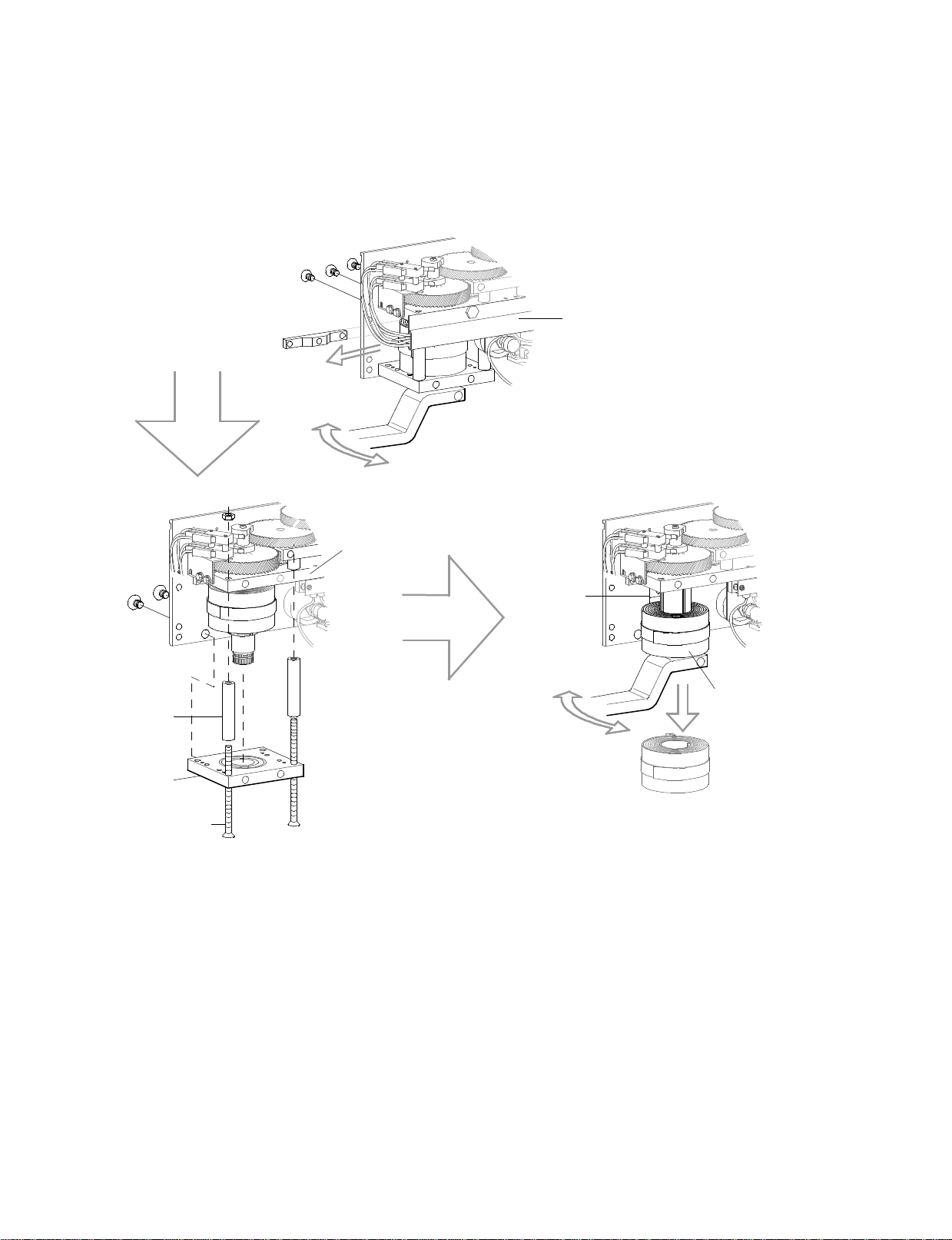
4th Step
Remove the two
assembly bolts, spacers
& lower bearing plate.
Note: Before proceeding
to next step, be carefull to
note location of inner
spring hook in output
shaft, as well as, the
direction the spring is
wound.
IF SPRING WAS BROKEN:
A. Replace new spring on output shaft. Be careful to place
inner spring hook in same slot in shaft as before.
B. Reinstall lower bearing plate with it's assembly bolts,
spacers and mounting screws.
C. Slide arm on output shaft and manually rotate until the
outer spring hooks clip into the spring retainer bracket.
Next rotate the shaft approximately 1/2 turn (180°) and
hold in that position.
D. Reinstall chassis stop and secure with mounting screws.
Allow arm to slowly counter-rotate until the stop lug on
the output shaft rests against the chassis stop. The
spring is now preloaded for most general applications.
7.070d1
C7132
Lower Bearing
Mounting Plate
C7078
1/4-20 x 4"FHMS
C7043-1 Spacer
1/2"O.D. x 2 1/2"
C7079
1/4-20 x 4 1/2"FHMS
5th Step
Slide an arm back
on the operator
shaft and manually
rotate until outer spring hooks release from
spring retainer bracket. Slide arm off and
remove spring.
ClosingSpring:
C7050 Type'D',
C7051Types 'E'.
The following information is provided as a guide for:
• Removing and replacing a broken spring.
• Changing spring direction.
• Changing both spring direction and operator hand.
• Changing operator hand but not spring direction.
NOTE: IN ALL CASES, SECURE THE BASE PLATE OF THE GEAR TRAIN ASSEMBLY (PREFERABLY IN A VISE)
WITH THE OUTPUT SHAFT FACING UP.
10. CHANGING OPERATOR HAND AND/OR CLOSING SPRING
1st Step
Slide an arm on the operator shaft and manually rotate arm
approximately 1/4 turn to relieve pressure on chasis stop.
Hold in that position.
2nd Step
Remove three chassis mounting screws
thus allowing spring to slowly unwind
and push out the chassis stop.
Remove both arm and
chassis stop.
3rd Step
Remove the two screws for lower
bearing mounting
plate.
C576
5/16-18 x 1/2"
FHMS
C7130-1
Upper Bearing
Mounting Plate
C7037
Chassis
Stop
REMOVING THE SPRING:
C576
1/4-20 x 3/4"
FHSCS
G710.6
Optional Step
To clear work space, detach C7083
Wire Guide & Operator Wiring
Harness from upper bearing plate
and move out of way.