gebatronic Cody Universal 1/1 User manual

GB
X0504 V1.0
Cody Universal
1/1 1/2 1/3
Assembly, connection and maintenance of the device
may only be executed by personnel trained accordingly.
At this the underlying national and local regulations have
to be observed.

Note: Optional Cody Universal Service Tool
The Cody Universal Service Tool gives you the possibility to program
your Cody Universal conveniently to your re uirements.
A LCD display shows you every programming step, including the # of a
used memory slot, relays settings etc.
It also allows you to delete transponders and RC transmitters directly
by their used memory slot.
Ref. 00.STU0.00
The Cody Universal consists of a decoder and a control element.
Both units are connected by a simple two-wire cable without a
special plug. Programming of Universal's Cody via the keyboard
using the mastercode. With the Cody Universal 1/2 & 1/3 you
have the option to operate 2 or 3 gate drives or the like with just
one control element.
Mastercode:
The mastercode is a 8 digit numeral code necessary for all
programming procedures.
Only after the input of this code the appliance can be
programmed according to your specific needs.
The Cody Universal is preset by the company with the
mastercode 12345678.
Pass code:
The pass code is either a four or five digit numeral code, by which
you operate your door drive unit. You have the possibility to store
up to 50 different pass codes, which means that up to 50 persons
with individual pass codes can open the door. If you are
accompanied by another person when entering your pass code
you can first press as many keys as you like before you finally
enter your code. This ensures that no other person can
notice your pass code. The Cody Universal is preset with the
pass code 1234 on memory slot 00.
Device description

ATTENTION!!!
After you have made yourself familiar with the functions of the
appliance, please program your personal mastercode as well as a
pass code with which you replace the pass code which is located
on the memory place 00. Only by this your Cody Universal is
protected against manipulation!
TIPTOMATIC:
Especially for garage doors the Cody Universal is designed with
TIPTOMATIC timing. After entering a pass code and within a period of
60 seconds (adjustable) this function allows you to control the door
with any key, except for the button, and without the need to enter
the pass code once again. This function, however, can be interrupted
prior to the expiration of the 60 seconds, by pressing the button.
Lock-out function:
If the lock-out function is activated, the Cody Universal automatically
blocks any input for a set period after the input of a wrong pass code
which is signalled with a (3 beeps) sound signal.
By choice, you can arrange that the lock-out time can be doubled after
any wrong input until a correct pass- or mastercode is entered.
The end of the lock-out time is signalled by a long sound signal.
Factory settings (default settings):
all memory slots erased (except 00)
mastercode = se uence 1-8
pass code 00 = se uence 1-4
relay 1 active
control mode = Tiptomatic
Tiptomatic time = 60 sec.
switching time = 1 sec.
lock-out time = 20 sec.
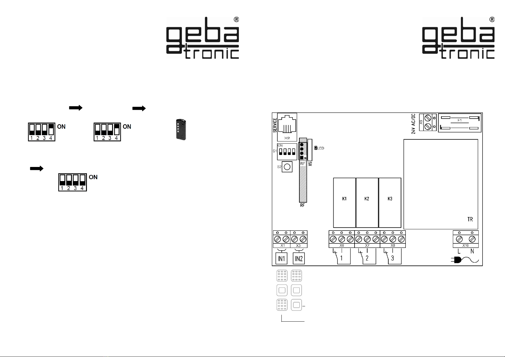
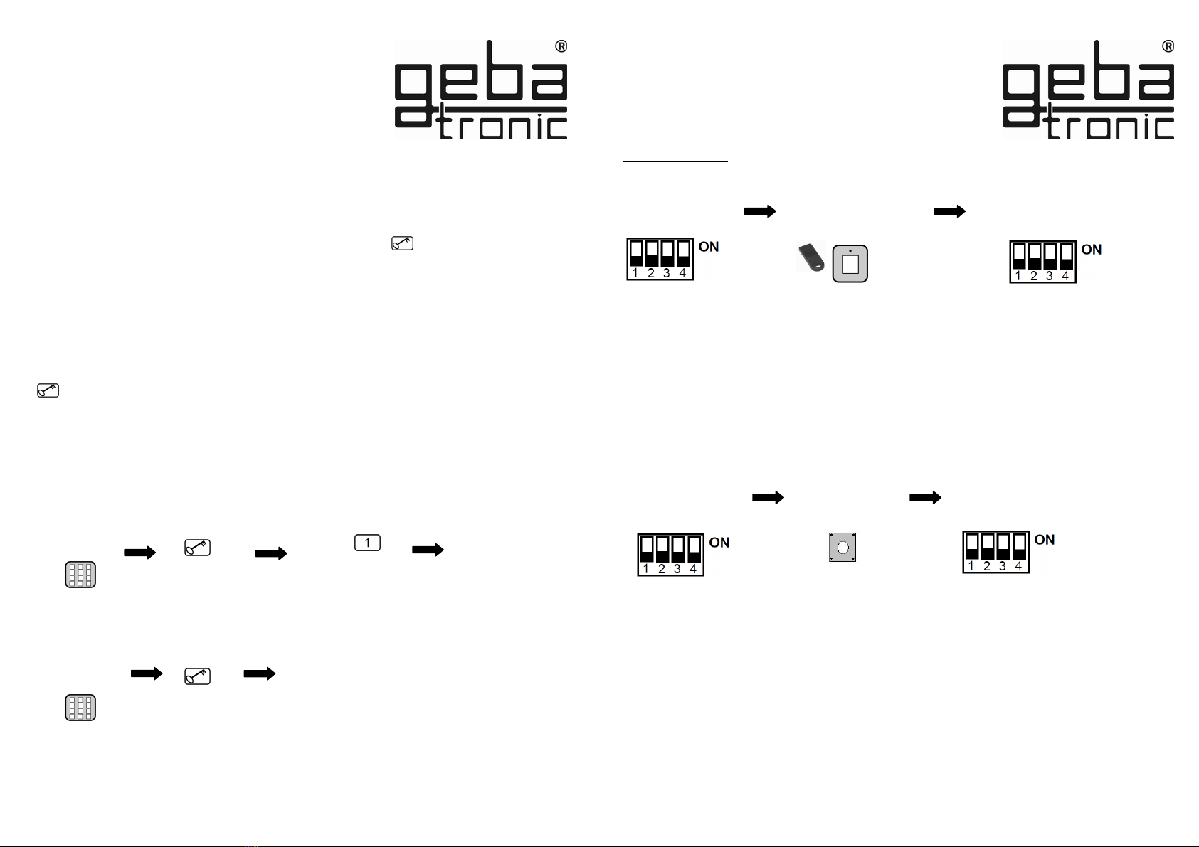
General reset
All factory settings are restored by the general reset !
Put DIP switch 4 to
ON
Push reset button
on the PCB
> 5 sec.
Put DIP switch
back to OFF
General reset

The specific transmitter is now deleted!
geba GmbH is released of its obligations regarding guarantee and product liability if – without prior
permission - the unit has been modified, or if the installation is unproper or not in accordance with our
instruction manual. The installer has to take care that the EMC-regulations are respected.
Interior mounting of the logic:
1. Put the screw-driver into the gap of the enclosure front, push the screw-driver up and
open the enclosure.
2. Remove the control PCB (which is force fitted to the inside of the enclosure).
3. Locate the screwed glands supplied (sealing nipple left side) in the
enclosure and replace the PCB. (Please ensure PCB is firmly in position)
4. Bore the fastening holes and fix the enclosure bracket at the wall.
5. The wires for the keyboard ensure through the left cable entry (sealing nipple), the wires
for the relay contact through the middle cable entry and the wires for the supply voltage ensure
through the right cable entry. Ensure tight seating of sealing nipple and cable gland, otherwise the
water-protection of the appliance cannot be assured.
6. According to connection diagram connect the wires to the corresponding terminals.
RC transmitter
Program 2
Deleting of remote controls
Delete specific transmitter:
The taught-in transmitters of the selected relays are now all
deleted !
Set DIP of the
relays used
(1/2/3) to ON
Press the button of the
RC transmitter
> 5 sec.
Put all DIP to OFF
Press the reset
button on the
logic board
> 5 sec.
Put
DIP 4 to ON LED flashes
2x long
Delete all transmitters of a single relay:
Put all DIP to OFF
Mounting instructions
Put
DIP 4 to ON
Set DIP of the
relays used
(1/2/3) to ON

Program 1
Teach-in of remote controls Technical data
Supply voltage: 20-28V AC/DC, 230-240 V AC
Output: 250V AC 5A
Connections: 1.5 mm² max.
Ambient temperature: -20 °C to +60 °C
RC transmitter
Make sure before the teach-in that the optional wireless module is plugged in firmly at the logic board.
The transmitter is programmed to the desired relay!
Put DIP 4 to ON
Press the desired
button on the remote
control LED flashes
1x long
Transponder
Cody
This product complies with:
EC Electromagnetic Compatibility Directives
EN 61000-6-1 08/2002
EN 61000-6-3 08/2002
Low Voltage Directive 2006/42/EC
Assembly versions - potential free contacts
Cody Universal 1 / 1 = X6
Cody Universal 1 / 2 = X6 + X7
Cody Universal 1 / 3 = X6 + X7 + X8
Put DIP of the
relay used
(1/2/3) to ON
Put all DIP to OFF
230/240VAC

Factory setting = 1-8
Programming
instructions
Keypad
Please read first - then do programming!!!
Program 1
Input of a new mastercode
Before programming your Cody Universal with your personal codes, please check the faultless function
of the appliance with the help of the factory‘s pass code 1234 and the button.
Usually, any programming is made via your personal mastercode. In order to get familiar with that kind
of programming, you start with the input of a new pass code, which replaces the one preset by the
factory (1234). The procedure is explained under item “Program 2“.
After that please change the factory set mastercode to your personal code of choice.
Attention / Note
In case you made a mistake on programming, you can start over again by pushing of the
button
Sound signal
2x long
Sound signal
1x long
Enter 8 digit
NEW
mastercode
Enter 8 digit
mastercode
The new mastercode is now saved!
push
button
All keys of this specific relay or block are now deleted !
Program 2
Deleting transponder keys
Delete specific keys:
Transponder
The individual transponder key is now deleted!
Put DIP of the
taught-in key
to ON
Put the desired
key to the
reader
LED flashes
2x long
Put DIP of the
specific block or
relay (1/2/3) to ON
Delete all transponder keys of an individual relay or block:
Press reset button
on the logic board
> 5 sec Set all DIP to
OFF
push
button
button
push
Set all DIP to
OFF

Program 1
Teach-in of transponder keys
Transponder
sound signal
2x long
Enter 8 digit
mastercode
The new pass code is now saved!
The entered pass code is now stored in the selected memory slot and
connected to the specified output!
Program 2
Creating a new pass code
Factory setting = 1- 4
Keypad
The transponder key is programmed to the desired
relay or block!
Put the desired
key to the
reader
LED flashes
1x long
Set all DIP to
OFF
Put DIP of the
desired relay or block
* (1/2/3) to ON
*Note:
Cody Universal 1/1
The keys are distributed among three blocks of 255 keys per color. The blocks correspond to the first
3 DIP switches.
Cody Universal 1/2 , Cody Universal 1/3
Here the blocks are allocated to the relay i.e. 255 keys per relay, DIP 1 = relay 1, etc.
If more than one key (of the same color only!) is taught-in, the DIP can remain in the ON position. The
successful teach-in of every key is confirmed by the illumination of the reader's LED. After the last key
has been taught-in, the DIP switch is reset to its initial position (OFF).
ATTENTION:
It is not possible to teach-in keys of different colors in one and the same block!
The reader should not be mounted directly on metal. Then use a spacer case (No. 508.000G.00).
Enter 4 or 5
digit pass code
Enter 2 digit
memory slot,
e.g. 07 or 28
sound signal
1x long
button
push
Only for Cody Universal 1/2 or 1/3
Set relay output to #
You can enter up to 0 different pass codes on the memories 00-49!
sound signal
1x long
push
button
push
button
push
button

Program 3
Deleting a pass code
Keypad
A correct code is detected; the corresponding relay is switched!
Before the actual pass code, you can press any other keys to prevent fraud.
If an incorrect pass code is entered, you will hear a sound signal (3 beeps).
Entering a new pass code is only possible after the lock-out period (factory: 20 sec.) which end is
signalled by a long sound signal.
Program 8
Entering a pass code
Keypad
The selected memory slot of the pass code
is now deleted!
Enter of 2 digit
memory slot,
e.g. 07 or 28
Enter 4 or 5 digit
pass code
sound signal
2x long
Enter 8 digit
master code
sound signal
1x long
push
button
push
button
push
button
push
button
button
push
sound signal
1x long

Program 7
Entering the control mode
Keypad
The switching time is allocated to the relay accordingly!
Program 4
Changing the control time - switching time
Keypad
The control mode is changed!
* control mode:
Button = Pulse mode (switching time factory 1 sec.)
Switch = Toggle mode (1st signal: relay switches, 2nd signal: relay switches off)
Tiptomatic = within the set Tiptomatic time (factory 60 sec.)
the relay can be switched again by pressing any key (except ),
without entering the pass code again
The Tiptomatic function is disabled once the control mode button or switch is selected.
Entering the control mode*:
Button
Switch
Tiptomatic
Enter 3 digit
time 001-255
Identical switching time
for all relays
= relays 1
= relays 2
= relays 3
sound signal
2x long
Enter 8 digit
mastercode
sound signal
1x long
push
button
push
button
push
button
Enter 8 digit
mastercode
button
push sound signal
2x long push push
button button
sound signal
1x long
sound signal
1x long
push
button
push
button

Program
Changing the control time - Tiptomatic-time
Keypad
The modified lock-out time is saved!
Program 6
Changing the control time - lock-out time
Keypad
The modified Tiptomatic time is saved!
This set time is the same for all relays (factory 60 sec.).
= dynamic*
= static*
*Lock-out time:
dynamic = The lock-out time is extended by 10 sec. with
every wrong entry (max. 255 sec.)
static = The lock-out time is always the set time (000 = turned off)
sound signal
2x long
Enter 8 digit
mastercode
sound signal
1x long
push
button
push
button
push
button
push
button
Enter 8 digit
mastercode
Enter 3 digit
time 001-255
Enter 3 digit
time 001-255
button
push
push
button button button
push push
button
push
sound signal
1x long
sound signal
1x long
sound signal
2x long
Other manuals for Cody Universal 1/1
1
This manual suits for next models
2
Table of contents
Other gebatronic Garage Door Opener manuals
Popular Garage Door Opener manuals by other brands

Chamberlain
Chamberlain Security+ 9950 owner's manual

BFT
BFT TIZIANO B GDA 260 S01 Installation and user manual

Beninca
Beninca BULL 1024 ESA manual

Chamberlain
Chamberlain Power Drive PD100C Series owner's manual

Doco
Doco EXS40R instruction manual

Chamberlain
Chamberlain LiftMaster CSW24V installation manual

INSTEON
INSTEON 74551 quick start guide

Merlin
Merlin SilentDrive Elite MR855MYQ Installation and operating instructions

Performax
Performax 24220 user manual

BFT
BFT DEIMOS ULTRA BTA400 User manual and installation manual

GLG
GLG RolliZIP Installation and Maintenance

krispol
krispol STARCUS K06 installation manual