Hosen Moving Head Spot User manual

HEADMOVING SPOT
USER MANUAL
100W/200W LED Moving Head Spot Light

2
3
6
7
10
12
13
14
4
22
23
21
20
11
18
17 15
4
4
4
4
5
16
70 lenses
120 lenses
Wheel fixer
Head cover
Motor driver board
Back cover
Pan belt
Master PCB
LED driver PCB
ABLE OF CONTENTS
T
PART 1 PRODUCT SPECIFICATIONS............................................1.
1.1--PRODUCT SPECIFICATIONS.......................................................1.
1.2--DIMENSIONS..............................................................................2.
1.3--PRODUCT FEATURES................................................................3.
PART 2 INSTALLATION................................................................5.
2.1--MOUNTING...................................................................................5.
2.3--FUSE REPLACEMENT..................................................................6.
2.2--SETTING UP.................................................................................6.
PART 4 USING DMX512 CONTROLLER........................................12.
4.1--BASIC ADDRESSING ................................................................ 12.
PART 3 DISPLAY PANEL OPERATION............................................8.
3.1--BASIC..........................................................................................8.
3.3--INTRO..........................................................................................9.
3.2--MENU..........................................................................................8.
3.4--INVERT........................................................................................10.
3.7--EDIT............................................................................................11.
1.4--SAFETY WARNING......................................................................4.
3.8--DEFAULT....................................................................................12.
PART 5 APPENDIX........................................................................17.
6.1--MAINTENANCE........................................................................17.
4.2--CHANNEL ASSIGNMENT........................................................... 12.
3.5--RANGE........................................................................................10.
3.6--SPECIAL......................................................................................11.
5 APPENDIX
5.1 MAINTENANCE
911
Power switch
Fuse
Handle
XRL Plug(male/female)
Motor
LED PCB
Fan
Rotation gobo wheel
Color wheel
Arm
Display PCB
Power socket
No ITEM No ITEM No ITEM
Head cover
Tilt belt
2.3--GOBO REPLACEMENT.................................................................7.

1 PRODUCT SPECIFICATIONS1 PRODUCT SPECIFICATIONS
Electrical
Voltage:AC100~240V 50/60Hz
Rated Power:220W
LED
LED:1PC(130W white)
Cooling:Forced air convection
Optical System
Focus:Electronic linear focus
Focus:Electronic focus
Dimmer:0~100%
Strobe:0~20Hz
Rotating 3-facet Prism
Operation
Control mode: DMX512/Master-Slave/Auto/Custom/Sound
LCD display
DMX512 Chs:12CHS/ 16CHS
Pan/Tilt
Pan 540 Tilt 270
Pan/Tilt speed
User-selectable Pan/Tilt ranges
Reverse Pan/Tilt movement
Rotating Gobo
6Gobo (interchangeable)
Gobo-flow effect
Gobo shake
Bi-directional rotation
Color
7 dichroic -filters + white
Rainbow - floweffect
Other features
Custom program (255steps)
Size:387x321x605mm
Weight:22kg
1.1 PRODUCT SPECIFICATIONS
LED:1PC(90W white)

1.2 DIMENSIONS
NO GOBO
GOBO 1
GOBO 2
GOBO 3
GOBO 4
GOBO 5
GOBO 6
Shaking gobo 6
Shaking gobo 5
Shaking gobo 4
GOBO 2
Flow effect
Shaking gobo 3
Shaking gobo 2
Shaking gobo 1
CHANNEL FUNCTION
VALUE
DIMMER
Dark Bright
FOCUS
NearFar
GOBO WHEEL 2 ROTATION
No function
Clockwise rotate from slow to fast
Anti-clockwise rotate from slow to fast
NO FUNCTION
Prism clockwise rotation (slow to fast)
NO FUNCTION
Prism anti- clockwise rotation (slow to fast)
White
PRISM & PRISM ROTATION
indexing
GOBO WHEEL 1 ROTATION
No function
Clockwise rotate from slow to fast
Anti-clockwise rotate from slow to fast
indexing
ZOOM
Zoom 1
Zoom 2
STROBE
Close
Open
Strobe: Slow > Fast
Rulse strobe effect: Slow> Fast
Random strobe effect: Slow> Fast
Open
Open
Open

1.3 PRODUCT FEATURES
1
2
3
4567
8910
11
12
No
1
2
3
4
5
6
ITEM
Head
Side arm
Handle
Menu
Enter
Down
No
7
8
9
10
11
12
ITEM
Up
Switch
Power input
DMX 3-PIN signalinput
DMX 3-PIN signaloutput
Fuse holder
STROBE
Close
Open
Strobe: Slow > Fast
Rulse strobe effect: Slow> Fast
Random strobe effect: Slow> Fast
Open
Open
Open
No function
Pan/tilt black activated (activated after 3 secs)
Pan/tilt black deactivated (activated after 3 secs)
No function
Auto1
Auto2
Test
Custom
Sound 1
Sound 2
CONTROL
Reset
No function
CHANNEL FUNCTION
VALUE
BASIC
CHANNEL FUNCTION
VALUE
PAN
0~540
TILT
0~270
COLOR WHEEL
Red
Green
Orange
Blue
Light Green
Yellow
Rainbow or linear effect
Magenta
NO GOBO
GOBO 1
GOBO 2
GOBO 3
GOBO 4
GOBO 5
GOBO 6
Shaking gobo 6
Shaking gobo 5
Shaking gobo 4
FIXED GOBO WHEEL
Flow effect
Shaking gobo 3
Shaking gobo 2
Shaking gobo 1

1.4 SAFETY WARNING
IMPORTANT
This product must be installedby a qualified professional.
Always operatethe equipment as described in the user manual.
A minimumdistance of 0.5m must be maintained between the equipment
and combustible surface.
The product must always beplaced in a well ventilated area.
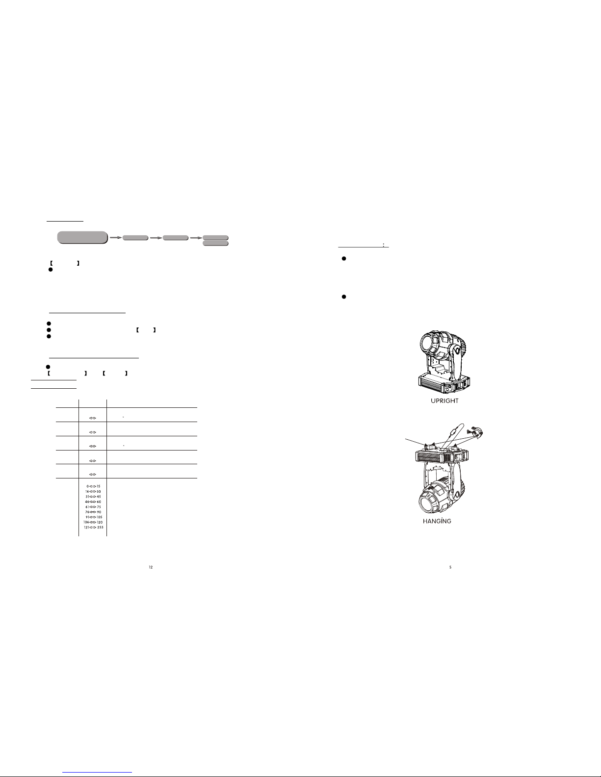
Always make sure that theequipment is installed securely.
DO NOT stand close tothe equipment and stare directly intothe LED light
source.
Always disconnect the power supplybefore attempting and maintenance.
Always makesure that the supporting structure is solid and can support
the combined weightof the products.
The earth wire must alwaysbe connected to the ground.
Do not touchthe power cables if your hands are wet.
This product leftthe place of manufacture in perfectcondition. In order to
maintain this conditionand for safe operation, the user must always follow
the instructions andsafety warnings described in this user manual.
Avoid shaking or strongimpacts to any part of theequipment.
Make sure thatall parts of the equipment are kept clean and free of dust.
Always makesure that the power connections are connected correct and
secure.
If there isany malfunction of the equipment, contact your distributor
immediately.
I t isimportant that the power cable is frequently inspected to ensure that
there is nodamagein any position. If the power cable is damaged in any way,
it should bereplaced by a qualified electrical technician.
When transferring theproduct, it is advisable to use the original packaging
in which theproduct left the factory.
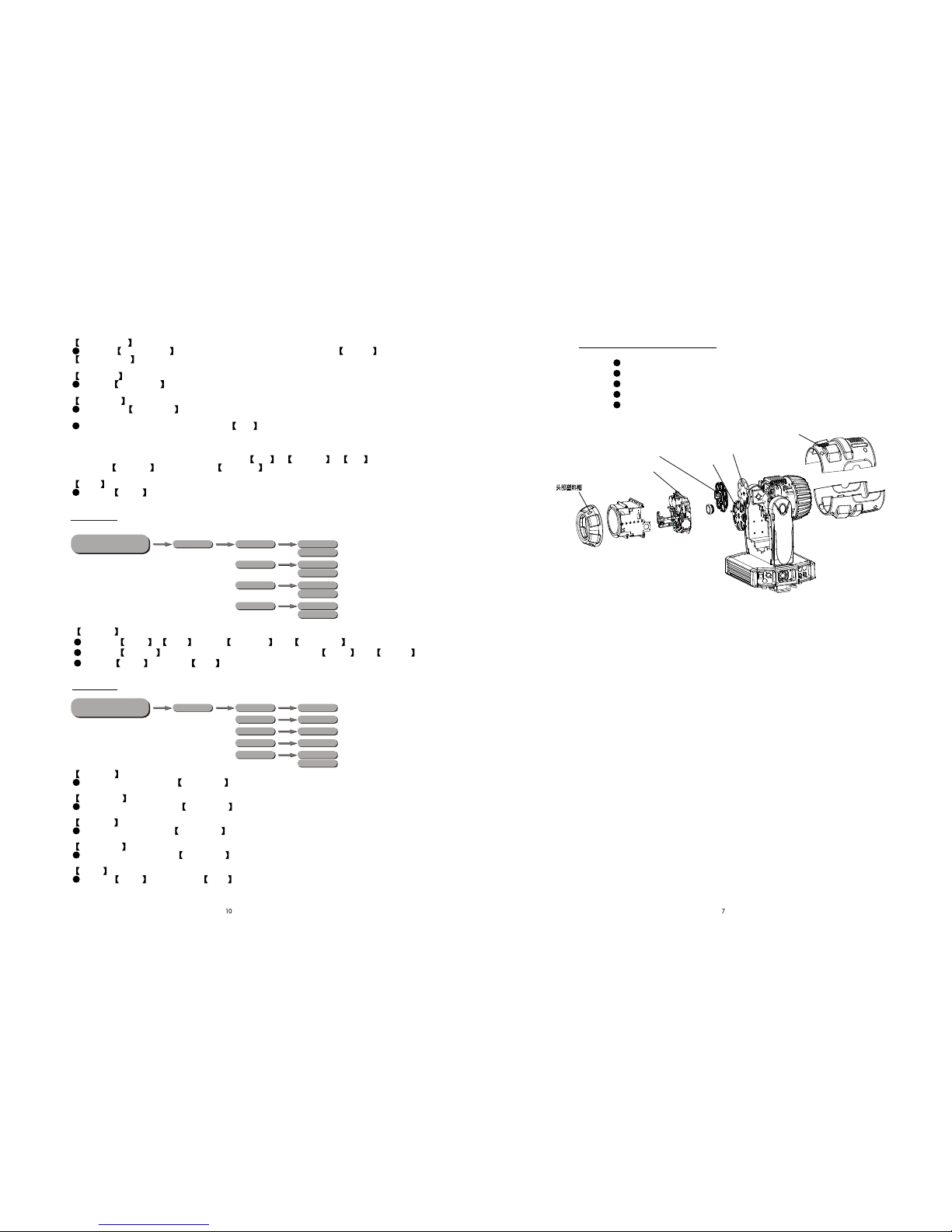
Shields, lenses orultraviolet screens shall be changed if they have
become damaged to such an extentthat their effectiveness is impaired.
The lamp (LED) shall bechanged if it has become damagedor thermally
deformed.
CHANNEL FUNCTION
VALUE
NO GOBO
GOBO 1
GOBO 2
GOBO 3
GOBO 4
GOBO 5
GOBO 6
Shaking gobo 6
Shaking gobo 5
Shaking gobo 4
FIXED GOBO WHEEL
Flow effect
Shaking gobo 3
Shaking gobo 2
Shaking gobo 1
NO Gobo
Gobo 1
Gobo 2
Gobo 3
Gobo 4
Gobo 5
Gobo 6
Shaking gobo 6
Shaking gobo 5
Shaking gobo 4
Shaking gobo 3
Shaking gobo 2
Shaking gobo 1
Flow effect
GOBO WHEEL 1 &GOBO SHAKE
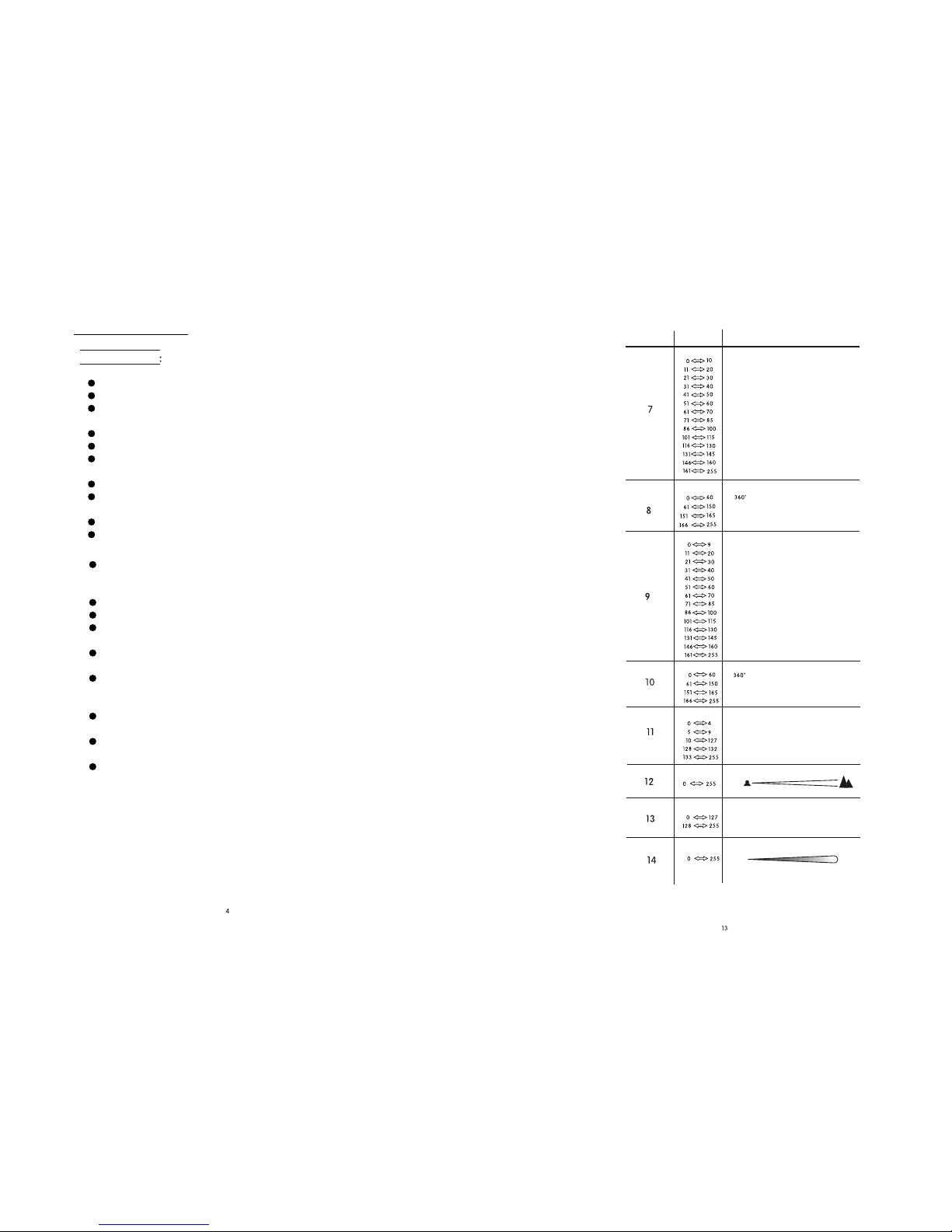
DIMMER
Dark Bright
FOCUS
NearFar
GOBO WHEEL 2 ROTATION
No function
Clockwise rotate from slow to fast
Anti-clockwise rotate from slow to fast
PRISM & PRISM ROTATION
NO FUNCTION
Prism clockwise rotation (slow to fast)
NO FUNCTION
Prism anti- clockwise rotation (slow to fast)
White
indexing
GOBO WHEEL 1 ROTATION
No function
Clockwise rotate from slow to fast
Anti-clockwise rotate from slow to fast
indexing
ZOOM
Zoom 1
Zoom 2

2.1
MOUNTING
The LED fixturecan be operated in any position at any angle. When mounted
on a flatsurface, the surface must be strong enough to support 10 times the
weight of thefixture and stable so that there will be no damage caused to the
fixture or surroundingpeople or objects because of movements of the fixture
on the surface.
When the unitis mounted in a hanging position, the fixture is attached using the
mounting brackets anda standard truss clamp or other clamping device. The
mounting brackets suppliedare mounted using quick-release locks allowing
simple mounting orremoval.
CLAMP
SAFTY CABLE
BRACKET
2 INSTALLATION
IMPORTANT SAFETY NOTE!!
Always use asafety cable when installing this unit!!
Be sure thatthe safety cable is connected to a solid load-bearing structure.
3.8 DEFAULT
Default Default No
Yes
MENU
Default
This functions will reset all settingto the original factory setting
ADVANCED
Connect all of the unitsin series using standard DMX512 signal cable .
Set the DMX512 address inthe DMX menu.
It is possible to havethe same DMX address or independent addresses for each
fixture.
4.2 CHANNEL ASSIGNMENT
4.1 BASIC ADDRESSING
Note: This product have twoDMX512 channel configuration:
ADVANCED and BASIC .
4 USING A DMX512 CONTROLLER
COLOR WHEEL
1
2
3
4
5
6
0 255
0 255
0 255
0 255
0 255
PAN
TILT
TILT FINE
PAN/TILTSPEED
0~540
PAN FINE
Fine control of panmovement
0~270
Fine control of tiltmovement
From fast to slow
CHANNEL FUNCTION
VALUE
NO
Green
Orange
Blue
Light Green
Yellow
Red
Rainbow or linear effect
Magenta

SAFTY CAP
FUSE
F
I
I
Remove the safetycap by ascrewdriver.
etch the oldfuse from safety cap.
nstall a newfuse.
nstall the safetycap.
2.3 FUSE REPLACEMENT 3.7 EDIT
Edit
Enter the Edit mode to editthe custom programs by adjusting the
value of Step ,Pan ,Tilt ,Color ,Gobo 1 , Gobo1rot ,
Gobo 2 ,Gobo2rot ,Prism ,Iris ,Focus ,Zoom ,
Strobe ,Time
Use Yes
ime
ime Use
ime Use
ime Use
Enter and select to run thesteps user need.
Note: if user wantto circulate the created steps, please set the laststep's
Tas 0
For example, thereare 3 steps, the setting should be like belowed:
Step 1 T= 4 = Yes
Step 2 T= 5 = Yes
Step 3 T= 0 = Yes
3.6 SPECIAL
Black
Enter Black to choose No without delay or Yes 3seconds
delay
Reset
Enter Reset to choose DMX DMX control resetor System DMX
cannot control reset
.
Zoomblack
Enter [Zoomblack] to choose automaticblackout when zooming
The LED fixture can be used as a stand alone unit. The stand alone
functions AUTO 1, AUTO 2, SOUND 1, SOUND2 and CUSTOM can be
activated without the need to connect to any controller or connecting to
any other equipment.
Simply, access the <operation> menu from the DISPLAY and select the
target program toactivate.
2.2 SETTING UP (STAND ALONE)

2.4 GOBO REPLACEMENT
Channels
Channels Basic
Advanced .
Display
Display
Keylock
Enter the Keylock mode to select whether the access password is on
or off.
When the fixtureis set as PASS ON , after 30 seconds or turn on the
fixture next time,the fixture will need an access password to enter the
display menu control.
Note: The factory access password is UP +DOWN +UP
+DOWN , then press ENTER to confirm theaccess.
Info
Info
Enter to select theDMX channel modes: ;
Enter to select thelighting time ofthe LCD display panel.
Enter to see theversion of the software.
3.4 INVERT
Use
Tilt
Color
Invert Pan Normal
Reverse
Normal
Linear
Reverse
Step
No
Yes
MENU
Normal Reverse
Use Yes
Invert
Select Pan /Tilt to set or
Select Color to select thecolor wheel flow way Step or linear
Enter and set to run thenew setting
3.5 RANGE
P/start
P/Finish
T/start
T/Finish
Use
Range (000~255)
No
Yes
(000~255)
(000~255)
(000~255)
MENU
P/start
P/Finish
T/start
T/Finish
Use
Use Yes
Set pan startvalue 000~255
Set pan finishvalue 000~255
Set Tiltstart value 000~255
Set Tiltfinish value 000~255
Enter and select to open theoperation of X/Yangle
I
Take off the head and mouth cover .
Remove the prism supports;
Remove the Rotating Gobo wheel supports
Replace the Gobos or Colors.
nstall all parts on the original position.
Rotating gobo wheel supports
Mouth cover
Static gobo wheel
Rotating gobo wheel Color wheel
Head cover

3.1 BASIC
MENU Scroll through the main menu orexit from the current sub-menu
ENTER Enter the currentlyselected menu or confirm the current function
value
DOWN Scroll 'DOWN' through the menu listor decrease the value of the
current function
UP Scroll 'UP' throughthe menu list or increase the value of the
Current function
3DISPLAY PANEL OPERATION
3.2 MENU
3.3 INTRO
Reset
Reset
Run
Run DMAX512 Auto1
Auto2 Custom Test Slave
Address
Enter Address to set theDMX Address, which is from (001-512)
In order torest custom modest to default, select
Enter to select theoperation mode: ; ;
; Sound 1 ;Sound 2 ;;;
Table of contents