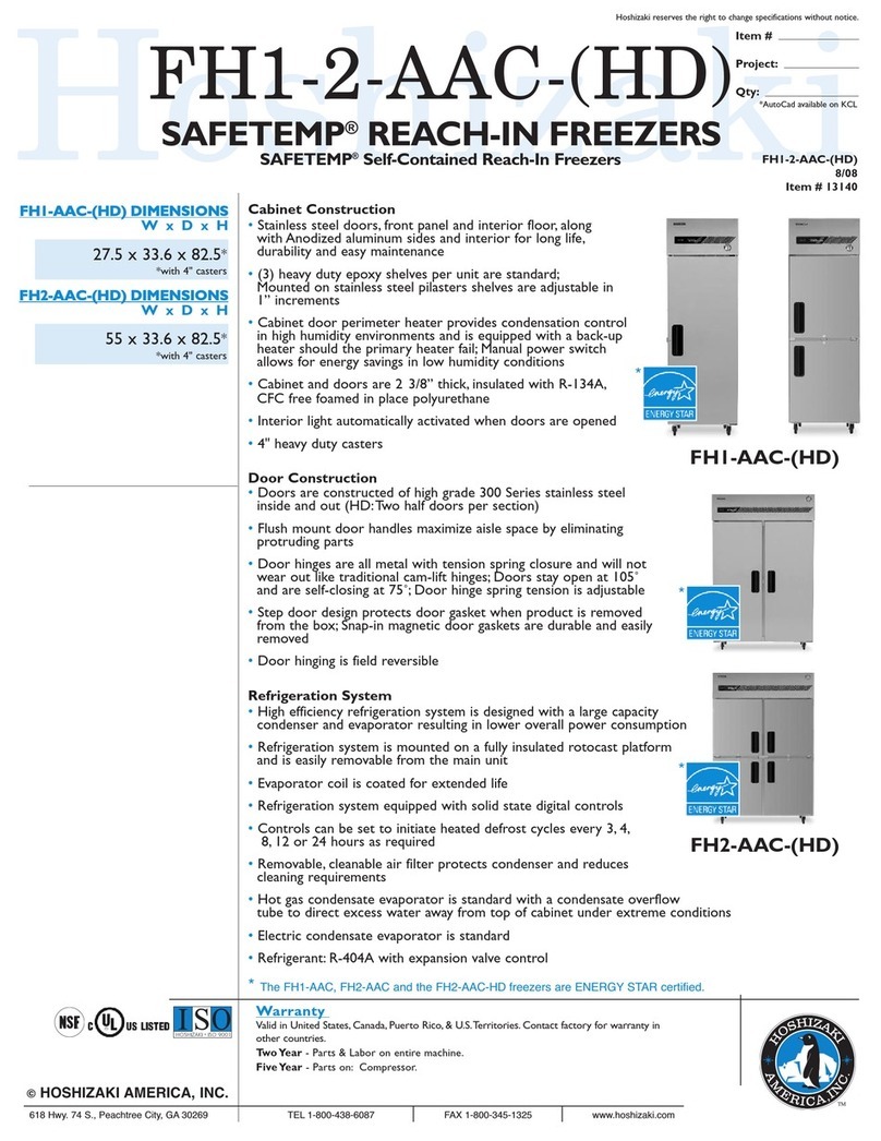
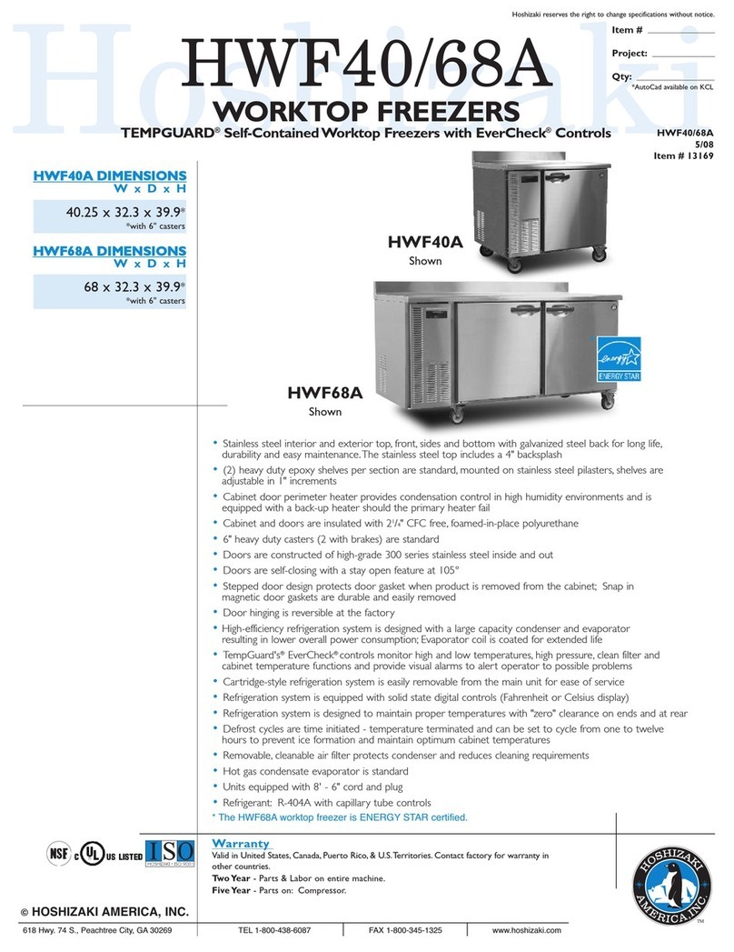
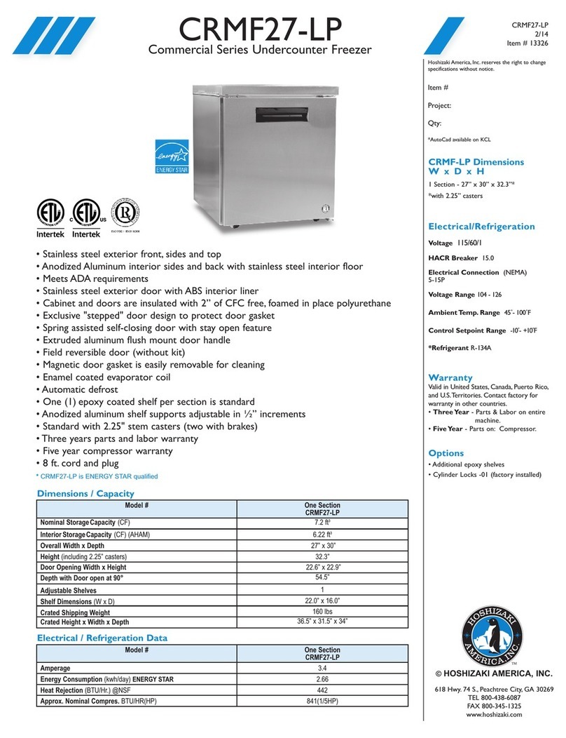
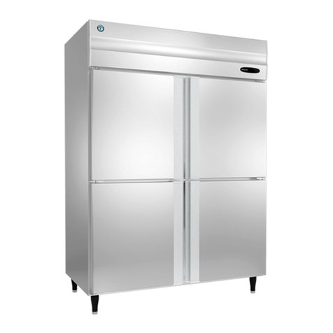
Hoshizaki RTE-80SFA(-UK) User manual

NO. E4AA-657
ISSUED: JUN. 29, 2004
REVISED: AUG. 20, 2004
HOSHIZAKI
UNDERCOUNTER
REFRIGERATOR/FREEZER
SERVICE MANUAL
MODEL RTE-80SFA(-UK)
RTE-125SFA(-UK)
RTE-170SFA(-UK)
FTE-80SFA(-UK)
FTE-125SFA(-UK)
FTE-170SFA(-UK)

i
CONTENTS PAGE
I.GENERALINFORMATION--------------------------------------------------------------------------- 1
1.SAFETYINSTRUCTIONS ------------------------------------------------------------------------- 1
2.CONSTRUCTION ----------------------------------------------------------------------------------- 3
3. MODEL NAME--------------------------------------------------------------------------------------- 4
4.SPECIFICATIONS ---------------------------------------------------------------------------------- 5
[a] RTE-80SFA(-UK) ------------------------------------------------------------------------------- 5
[b] RTE-125SFA(-UK)------------------------------------------------------------------------------ 6
[c] RTE-170SFA(-UK) ------------------------------------------------------------------------------ 7
[d] FTE-80SFA(-UK)-------------------------------------------------------------------------------- 8
[e] FTE-125SFA(-UK) ------------------------------------------------------------------------------ 9
[f] FTE-170SFA(-UK) -----------------------------------------------------------------------------10
5.DIMENSIONS --------------------------------------------------------------------------------------- 11
[a] RTE/FTE-80SFA(-UK) ------------------------------------------------------------------------11
[b] RTE/FTE-125SFA(-UK) ----------------------------------------------------------------------12
[c] RTE/FTE-170SFA(-UK)-----------------------------------------------------------------------13
II.TECHNICALINFORMATION-----------------------------------------------------------------------14
1.WIRINGDIAGRAM ---------------------------------------------------------------------------------14
[a] RTE-80,125,170SFA--------------------------------------------------------------------------14
[b] FTE-80,125,170SFA --------------------------------------------------------------------------15
2.REFRIGERATIONCIRCUIT ----------------------------------------------------------------------16
3. SEQUENCE-----------------------------------------------------------------------------------------17
4. ELECTRONIC CONTROLS----------------------------------------------------------------------19
[a] SETPOINTTEMPERATURE ---------------------------------------------------------------19
[b] CABINETTEMPERATURE DIFFERENTIAL --------------------------------------------19
[c] DEFROST CYCLE-----------------------------------------------------------------------------19
[d] DEFROST COMPLETION TEMPERATURE --------------------------------------------19
[e] CLOGGED CONDENSER DETECTION TEMPERATURE --------------------------19
[f] TEMPERATURE DISPLAY CYCLE--------------------------------------------------------19
[g] COMPRESSOR SOFT START -------------------------------------------------------------20
[h] CABINET TEMPERATUREAND TEMPERATURE DISPLAY -----------------------20
[i] RESOLUTION-----------------------------------------------------------------------------------21
[j] CHECKINGANDADJUSTING SET POINT TEMPERATURE -----------------------21
[k] MANUAL DEFROST --------------------------------------------------------------------------21
[l] CANCELING SOFT START------------------------------------------------------------------21
5. ERROR CODES------------------------------------------------------------------------------------22
6.INTERMITTENTOPERATION -------------------------------------------------------------------28
7. HEATER LAYOUT ----------------------------------------------------------------------------------30
III. REMOVALAND REPLACEMENTOF COMPONENTS------------------------------------31
1.REFRIGERATIONUNIT ---------------------------------------------------------------------------31
2.REFRIGERATIONCIRCUIT ----------------------------------------------------------------------32
[a]REFRIGERANT---------------------------------------------------------------------------------32
[b] COMPRESSOR--------------------------------------------------------------------------------32
[c] EVAPORATORAND DEFROST HEATER-----------------------------------------------32
[d] CONDENSER ----------------------------------------------------------------------------------33
ii
3. CONTROL BOX ------------------------------------------------------------------------------------34
4. FAN MOTORS --------------------------------------------------------------------------------------34
[a] CONDENSER FAN MOTOR ----------------------------------------------------------------34
[b]INTERIORFANMOTOR ----------------------------------------------------------------------34
5.THERMISTORS-------------------------------------------------------------------------------------35
[a]INTERIORTHERMISTOR --------------------------------------------------------------------35
[b]DEFROSTTHERMISTOR -------------------------------------------------------------------35
[c]CLOG THERMISTOR -------------------------------------------------------------------------35
6. DOOR GASKET ------------------------------------------------------------------------------------36
[a] REMOVAL ---------------------------------------------------------------------------------------36
[b] REPLACEMENT-------------------------------------------------------------------------------36
Symbol Meaning
Keep Dry
Cabinet Temperature
IncreasingTemperature
Decreasing Temperature
Manual Defrost
Rapid Refrigeration

1
I. GENERAL INFORMATION
1. SAFETY INSTRUCTIONS
Thefollowinginstructionscontainimportantsafetyprecautionsandshouldbestrictlyobserved.
The terms used here are defined as follows:
WARNING: There is a possibility of death or serious injury for the service person and a third
party or the user due to improper service operations or defects in serviced
products.
CAUTION: There is a possibility of injury for the service person and a third party or the user
or damage to their property* due to improper service operations or defects in
serviced products.
* The term “damage to their property” here refers to extensive damage to household effects,
houses and pets.
WARNING
1. Always ask the user to keep children away from the work area. They may be injured by
tools or disassembled products.
2. When there is no need to energize the unit during disassembly or cleaning, be sure to
unplug the unit or disconnect the main power supply before servicing the unit to prevent
electric shocks.
3. If the unit must be energized for inspection of the electric circuit, use rubber gloves to avoid
contact with any live parts resulting in electric shocks.
4. Keep the following in mind when servicing the refrigeration circuit:
(1) Be sure to recover the refrigerant. Do not discharge it into the atmosphere. It will
affectthe environment.
(2) Check for any flames in the vicinity, and ensure good ventilation.
(3) If the refrigerant should leak in servicing, immediately put out any fire used in the
vicinity.
(4)Whenunbrazingtherefrigerationcircuitconnections,checkthatthecircuitiscompletely
evacuated. The refrigerant may produce a poisonous gas when coming in contact
with an open flame.
(5) Do not braze in an enclosed room to prevent carbon monoxide poisoning.
(6) In case of a refrigerant leak, locate and repair the leaking part completely. Leaked
refrigerantmayproduce a poisonous gaswhencomingin contact with anopenflame.

2
(7) Before servicing, check the surface temperature of the refrigeration circuit to prevent
aburn.
5. Keep the following in mind when making electrical connections:
(1) Check for proper grounding connections, and repair if necessary to prevent electric
shocks.
(2)Alwaysuseservicepartsintendedfortheapplicablemodelforreplacementofdefective
parts. Usepropertools tosecurethewiring. Otherwise abnormaloperationortrouble
may occur and cause electric leaks or fire.
(3)Checkforproperpartinstallations,wiringconditionsandsolderedorsolderlessterminal
connections to avoid fire, heat or electric shocks.
(4) Be sure to replace damaged or deteriorated power cords and lead wires to prevent
fire, heat or electric shocks.
(5) Cut-off lead wires must be bound using closed end connectors or the like, with their
closed ends up to avoid entrance of moisture that could lead to electric leaks or fire.
(6) After servicing, always use a megohmmeter (500V DC) to check for the insulation
resistance of at least 1 megohm between the live part (attachment plug) and the
dead metal part (grounding terminal).
(7) Do not service the electrical parts with wet hands to prevent electric shocks.
(8) The capacitors used for the compressor and other components may be under high
voltage and should be discharged properly before servicing.
CAUTION
1. After servicing, follow the instructions below:
(1) Check for water leaks in the water supply and drain pipes to prevent damage to the
vicinity including household effects.
(2) Always check the unit for proper operation before finishing services.
(3) Be sure to reassemble the parts completely. Loose assembly of such parts as control
boxcovermaycauseentranceofverminsresultinginashortcircuitbetweenterminals
and possible ignition.

3
2. CONSTRUCTION
RTE-170SFA
This refrigerator/freezer can be divided into the cabinet, refrigeration circuit, and electrical
parts.
1) The cabinet can be further divided into the food storage/refrigeration, condensing unit
and evaporator compartments.
The interior of the food storage/refrigeration and evaporator compartments is made of
stainless steel. The exterior of the side walls is covered with galvanized steel or stainless
steel with some in-between space filled with urethane foam for thermal insulation.
To allow access to the interior, the openings at the front are provided with doors made of
stainless steel on both the interior and exterior and filled with urethane foam for thermal
insulation.
The evaporator compartment is also equipped with an opening at the front to provide
access for removal of the evaporator for maintenance and service.
The condensing unit compartment is located below the evaporator compartment at the
left side of the unit. The condensing unit can slide in from the front on the galvanized steel
base.

4
2) The refrigeration circuit is composed of the compressor, condenser, drier, capillary tube
and evaporator. These components are connected with copper tubes, welded to make
them airtight, and charged with a specified amount of refrigerant R134a (refrigerator) or
R404A(freezer).
Theevaporator islocatedinsidetheevaporator compartment,while theothercomponents
are located inside the condensing unit compartment.
3) The electrical parts include the power supply cord attached to the cabinet; the anti-
condensation frame heater; the compressor, condenser fan motor, interior fan motor,
defrost heater, transformer and temperature control thermistor in the refrigeration circuit;
the controller board, relays, fuse and ground fault interrupter in the control box.
3. MODEL NAME
R T E - 80 S F A (-UK)
UK Model
TheonlydifferencesbetweentheUKmodelsand
othermodels arethis appliancetypecode“-UK”,
power supply cord and attachment plug.
Model Change Code
Alphabetical order
Depth
F: 700mm
Interior Material
S: Stainless steel
Width (cm)
Destination
E: Europe and other overseas countries
Product Type
T:Tabletype (Undercounter)
Product Category
R: Refrigerator
F: Freezer

5
4. SPECIFICATIONS
[a] RTE-80SFA(-UK)
AC SUPPLY VOLTAGE *
POWER SUPPLY CAPACITY *
AMPERAGE *
STARTING AMPERAGE *
ELECTRIC CONSUMPTION (RATED) *
ELECTRIC CONSUMPTION (ACTUAL)
POWER FACTOR *
1 Phase 230V 50Hz
0.52kVA (2.2A)
2.0A
8.2A
Motor: 310W Heater: 176W
Refrigeration: 321W Defrost: 165W
69%
PULLDOWN TIME (10°C to 0°C)
REACHED TEMPERATURE Approx. 9 min. (Ambient Temp. 43°C, No Load, 50Hz)
Approx. -17°C (Ambient Temp. 43°C, No Load, 50Hz)
EFFECTIVE CAPACITY
OUTSIDE DIMENSIONS [DRAWING NO.]
INSIDE DIMENSIONS
EXTERIOR
INTERIOR
INSULATION
132L
800mm(W) x 700mm(D) x 850mm(H) [3R6801]
394mm(W) x 527mm(D) x 589mm(H)
Stainless Steel
Stainless Steel
Polyurethane Foam
REFRIGERATION SYSTEM
DEFROST SYSTEM Forced Air Circulation Fan Motor 13W
Glass Tube Heater
COMPRESSOR
CONDENSER
EVAPORATOR
REFRIGERANT CONTROL
REFRIGERANT CHARGE
Hermetic 215W Model FR8.5G
FinandTubetype(8tubeshigh 4 rows deep), Fan Motor 4P 8W
Fin and Tube type (10 tubes high 3 rows deep)
Capillary Tube 1.0mm DIA x 2.0mm DIA x 3000mm long
R134a 245g
CABINET TEMPERATURE CONTROL
DEFROST CONTROL
Microprocessor
Adjustable from -6 to 12°C
Microprocessor
ELECTRIC CIRCUIT PROTECTION
COMPRESSOR PROTECTION Circuit Breaker (with Overcurrent Protector) 15A
Motor Protector (Auto-reset)
WEIGHT
PACKAGE Net weight 85kg / Gross weight 90kg
Carton 1005mm(W) x 780mm(D) x 835mm(H)
CERTIFICATION CE Marking
ACCESSORIES Shelf x 2
AMBIENT TEMP.
VOLTAGE RANGE 5 - 43°C
Rated voltage ±10%
* The electrical properties are based on measurements at ambient temperature of 43°C
according to the Technical Requirements for Electrical Appliances.

6
[b] RTE-125SFA(-UK)
AC SUPPLY VOLTAGE *
POWER SUPPLY CAPACITY *
AMPERAGE *
STARTING AMPERAGE *
ELECTRIC CONSUMPTION (RATED) *
ELECTRIC CONSUMPTION (ACTUAL)
POWER FACTOR *
1 Phase 230V 50Hz
0.52kVA (2.2A)
1.9A
8.2A
Motor: 290W Heater: 189W
Refrigeration: 314W Defrost: 174W
70%
PULLDOWN TIME (10°C to 0°C)
REACHED TEMPERATURE Approx. 16 min. (Ambient Temp. 43°C, No Load, 50Hz)
Approx. -13°C (Ambient Temp. 43°C, No Load, 50Hz)
EFFECTIVE CAPACITY
OUTSIDE DIMENSIONS [DRAWING NO.]
INSIDE DIMENSIONS
EXTERIOR
INTERIOR
INSULATION
279L
1250mm(W) x 700mm(D) x 850mm(H) [3R6802]
835mm(W) x 527mm(D) x 589mm(H)
Stainless Steel
Stainless Steel
Polyurethane Foam
REFRIGERATION SYSTEM
DEFROST SYSTEM Forced Air Circulation Fan Motor 13W
Glass Tube Heater
COMPRESSOR
CONDENSER
EVAPORATOR
REFRIGERANT CONTROL
REFRIGERANT CHARGE
Hermetic 215W Model FR8.5G
FinandTubetype(8tubeshigh 4 rows deep), Fan Motor 4P 8W
Fin and Tube type (10 tubes high 3 rows deep)
Capillary Tube 1.0mm DIA x 2.0mm DIA x 3000mm long
R134a 245g
CABINET TEMPERATURE CONTROL
DEFROST CONTROL
Microprocessor
Adjustable from -6 to 12°C
Microprocessor
ELECTRIC CIRCUIT PROTECTION
COMPRESSOR PROTECTION Circuit Breaker (with Overcurrent Protector) 15A
Motor Protector (Auto-reset)
WEIGHT
PACKAGE Net weight 113kg / Gross weight 121kg
Carton 1455mm(W) x 780mm(D) x 835mm(H)
CERTIFICATION CE Marking
ACCESSORIES Shelf x 4
AMBIENT TEMP.
VOLTAGE RANGE 5 - 43°C
Rated voltage ±10%
* The electrical properties are based on measurements at ambient temperature of 43°C
according to the Technical Requirements for Electrical Appliances.

7
[c] RTE-170SFA(-UK)
AC SUPPLY VOLTAGE *
POWER SUPPLY CAPACITY *
AMPERAGE *
STARTING AMPERAGE *
ELECTRIC CONSUMPTION (RATED) *
ELECTRIC CONSUMPTION (ACTUAL)
POWER FACTOR *
1 Phase 230V 50Hz
0.52kVA (2.2A)
2.0A
8.2A
Motor: 305W Heater: 202W
Refrigeration: 342W Defrost: 182W
72%
PULLDOWN TIME (10°C to 0°C)
REACHED TEMPERATURE Approx. 27 min. (Ambient Temp. 43°C, No Load, 50Hz)
Approx. -9°C (Ambient Temp. 43°C, No Load, 50Hz)
EFFECTIVE CAPACITY
OUTSIDE DIMENSIONS [DRAWING NO.]
INSIDE DIMENSIONS
EXTERIOR
INTERIOR
INSULATION
432L
1700mm(W) x 700mm(D) x 850mm(H) [3R6803]
1290mm(W) x 527mm(D) x 589mm(H)
Stainless Steel
Stainless Steel
Polyurethane Foam
REFRIGERATION SYSTEM
DEFROST SYSTEM Forced Air Circulation Fan Motor 13W
Glass Tube Heater
COMPRESSOR
CONDENSER
EVAPORATOR
REFRIGERANT CONTROL
REFRIGERANT CHARGE
Hermetic 215W Model FR8.5G
FinandTubetype(8tubeshigh 4 rows deep), Fan Motor 4P 8W
Fin and Tube type (10 tubes high 3 rows deep)
Capillary Tube 1.0mm DIA x 2.0mm DIA x 3000mm long
R134a 245g
CABINET TEMPERATURE CONTROL
DEFROST CONTROL
Microprocessor
Adjustable from -6 to 12°C
Microprocessor
ELECTRIC CIRCUIT PROTECTION
COMPRESSOR PROTECTION Circuit Breaker (with Overcurrent Protector) 15A
Motor Protector (Auto-reset)
WEIGHT
PACKAGE Net weight 140kg / Gross weight 149kg
Carton 1905mm(W) x 780mm(D) x 835mm(H)
CERTIFICATION CE Marking
ACCESSORIES Shelf x 6
AMBIENT TEMP.
VOLTAGE RANGE 5 - 43°C
Rated voltage ±10%
* The electrical properties are based on measurements at ambient temperature of 43°C
according to the Technical Requirements for Electrical Appliances.

8
[d] FTE-80SFA(-UK)
AC SUPPLY VOLTAGE *
POWER SUPPLY CAPACITY *
AMPERAGE *
STARTING AMPERAGE *
ELECTRIC CONSUMPTION (RATED) *
ELECTRIC CONSUMPTION (ACTUAL)
POWER FACTOR *
1 Phase 230V 50Hz
0.93kVA (4.0A)
3.0A
14.8A
Motor: 355W Heater: 350W
Refrigeration: 375W Defrost: 330W
52%
PULLDOWN TIME (-5°C to -15°C)
REACHED TEMPERATURE Approx. 9 min. (Ambient Temp. 43°C, No Load, 50Hz)
Approx. -30°C (Ambient Temp. 43°C, No Load, 50Hz)
EFFECTIVE CAPACITY
OUTSIDE DIMENSIONS [DRAWING NO.]
INSIDE DIMENSIONS
EXTERIOR
INTERIOR
INSULATION
132L
800mm(W) x 700mm(D) x 850mm(H) [3R6804]
394mm(W) x 527mm(D) x 589mm(H)
Stainless Steel
Stainless Steel
Polyurethane Foam
REFRIGERATION SYSTEM
DEFROST SYSTEM Forced Air Circulation Fan Motor 13W
Glass Tube Heater
COMPRESSOR
CONDENSER
EVAPORATOR
REFRIGERANT CONTROL
REFRIGERANT CHARGE
Hermetic 495W Model SC12CL
FinandTubetype(8tubeshigh 4 rows deep), Fan Motor 4P 8W
Fin and Tube type (10 tubes high 3 rows deep)
Capillary Tube 1.0mm DIA x 2.0mm DIA x 3000mm long
R404A 240g
CABINET TEMPERATURE CONTROL
DEFROST CONTROL
Microprocessor
Adjustable from -25 to -7°C
Microprocessor
ELECTRIC CIRCUIT PROTECTION
COMPRESSOR PROTECTION Circuit Breaker (with Overcurrent Protector) 15A
Motor Protector (Auto-reset)
WEIGHT
PACKAGE Net weight 87kg / Gross weight 92kg
Carton 1005mm(W) x 780mm(D) x 835mm(H)
CERTIFICATION CE Marking
ACCESSORIES Shelf x 2
AMBIENT TEMP.
VOLTAGE RANGE 5 - 43°C
Rated voltage ±10%
* The electrical properties are based on measurements at ambient temperature of 43°C
according to the Technical Requirements for Electrical Appliances.

9
[e] FTE-125SFA(-UK)
AC SUPPLY VOLTAGE *
POWER SUPPLY CAPACITY *
AMPERAGE *
STARTING AMPERAGE *
ELECTRIC CONSUMPTION (RATED) *
ELECTRIC CONSUMPTION (ACTUAL)
POWER FACTOR *
1 Phase 230V 50Hz
0.93kVA (4.0A)
3.0A
14.8A
Motor: 375W Heater: 373W
Refrigeration: 418W Defrost: 345W
57%
PULLDOWN TIME (-5°C to -15°C)
REACHED TEMPERATURE Approx. 18 min. (Ambient Temp. 43°C, No Load, 50Hz)
Approx. -25.6°C (Ambient Temp. 43°C, No Load, 50Hz)
EFFECTIVE CAPACITY
OUTSIDE DIMENSIONS [DRAWING NO.]
INSIDE DIMENSIONS
EXTERIOR
INTERIOR
INSULATION
279L
1250mm(W) x 700mm(D) x 850mm(H) [3R6805]
835mm(W) x 527mm(D) x 589mm(H)
Stainless Steel
Stainless Steel
Polyurethane Foam
REFRIGERATION SYSTEM
DEFROST SYSTEM Forced Air Circulation Fan Motor 13W
Glass Tube Heater
COMPRESSOR
CONDENSER
EVAPORATOR
REFRIGERANT CONTROL
REFRIGERANT CHARGE
Hermetic 495W Model SC12CL
FinandTubetype(8tubeshigh 4 rows deep), Fan Motor 4P 8W
Fin and Tube type (10 tubes high 3 rows deep)
Capillary Tube 1.0mm DIA x 2.0mm DIA x 3000mm long
R404A 240g
CABINET TEMPERATURE CONTROL
DEFROST CONTROL
Microprocessor
Adjustable from -25 to -7°C
Microprocessor
ELECTRIC CIRCUIT PROTECTION
COMPRESSOR PROTECTION Circuit Breaker (with Overcurrent Protector) 15A
Motor Protector (Auto-reset)
WEIGHT
PACKAGE Net weight 115kg / Gross weight 123kg
Carton 1455mm(W) x 780mm(D) x 835mm(H)
CERTIFICATION CE Marking
ACCESSORIES Shelf x 4
AMBIENT TEMP.
VOLTAGE RANGE 5 - 43°C
Rated voltage ±10%
* The electrical properties are based on measurements at ambient temperature of 43°C
according to the Technical Requirements for Electrical Appliances.

10
[f] FTE-170SFA(-UK)
AC SUPPLY VOLTAGE *
POWER SUPPLY CAPACITY *
AMPERAGE *
STARTING AMPERAGE *
ELECTRIC CONSUMPTION (RATED) *
ELECTRIC CONSUMPTION (ACTUAL)
POWER FACTOR *
1 Phase 230V 50Hz
0.93kVA (4.0A)
3.3A
14.8A
Motor: 430W Heater: 471W
Refrigeration: 495W Defrost: 435W
61%
PULLDOWN TIME (-5°C to -15°C)
REACHED TEMPERATURE Approx. 25 min. (Ambient Temp. 43°C, No Load, 50Hz)
Approx. -23°C (Ambient Temp. 43°C, No Load, 50Hz)
EFFECTIVE CAPACITY
OUTSIDE DIMENSIONS [DRAWING NO.]
INSIDE DIMENSIONS
EXTERIOR
INTERIOR
INSULATION
432L
1700mm(W) x 700mm(D) x 850mm(H) [3R6806]
1290mm(W) x 527mm(D) x 589mm(H)
Stainless Steel
Stainless Steel
Polyurethane Foam
REFRIGERATION SYSTEM
DEFROST SYSTEM Forced Air Circulation Fan Motor 13W x 2
Glass Tube Heater
COMPRESSOR
CONDENSER
EVAPORATOR
REFRIGERANT CONTROL
REFRIGERANT CHARGE
Hermetic 495W Model SC12CL
FinandTubetype(8tubeshigh 4 rows deep), Fan Motor 4P 8W
Fin and Tube type (10 tubes high 3 rows deep)
Capillary Tube 1.0mm DIA x 2.0mm DIA x 3000mm long
R404A 270g
CABINET TEMPERATURE CONTROL
DEFROST CONTROL
Microprocessor
Adjustable from -25 to -7°C
Microprocessor
ELECTRIC CIRCUIT PROTECTION
COMPRESSOR PROTECTION Circuit Breaker (with Overcurrent Protector) 15A
Motor Protector (Auto-reset)
WEIGHT
PACKAGE Net weight 143kg / Gross weight 152kg
Carton 1905mm(W) x 780mm(D) x 835mm(H)
CERTIFICATION CE Marking
ACCESSORIES Shelf x 6
AMBIENT TEMP.
VOLTAGE RANGE 5 - 43°C
Rated voltage ±10%
* The electrical properties are based on measurements at ambient temperature of 43°C
according to the Technical Requirements for Electrical Appliances.

11
5. DIMENSIONS
[a] RTE/FTE-80SFA(-UK)

12
[b] RTE/FTE-125SFA(-UK)

13
[c] RTE/FTE-170SFA(-UK)

14
II. TECHNICAL INFORMATION
1. WIRING DIAGRAM
[a] RTE-80,125,170SFA

15
[b] FTE-80,125,170SFA

16
2. REFRIGERATION CIRCUIT
Compressor
Capillary Tube
Heat Exchange
Condenser
Condenser Fan Moto
r
Drier
Interior Fan Motor
Evaporator
Drain evaporator
REFRIGERANT:HFC-R134a(RTE-*SFA)
:HFC-R404A(FTE-*SFA)

17
3. SEQUENCE
[a] REFRIGERATOR
1. When the power supply is turned on, the interior fan motor and frame heater will be
energized immediately, and the compressor and condenser fan motor after 3 minutes to
start the refrigeration process.
2. The interior thermistor controls operation at the set point temperature.
3. Every 6 hours after the power supply is turned on, the defrost thermistor will start a
defrost cycle if the temperature around the evaporator is 14.9°C or less. During the
defrost cycle, the temperature display window on the control box indicates “dF”. The
compressor, condenser fan motor and interior fan motor will stop, while the defrost heater
will be energized. When the defrost thermistor senses 15°C, the defrost heater will turn
off. The compressor and condenser fan motor will be energized after 5 minutes, and the
interior fan motor after another 5 minutes. Then, after 1 minute, the temperature display
window indicates the cabinet temperature. This is the end of the defrost cycle and the
start of the control operation.
Com
p
resso
r
Condenser
Fan Motor
Interior
Fan Motor
Defrost Heate
r
Frame Heate
r
Power ON
3 min
Defrost starts
Defrost
Thermistor senses
Drain ends Dis
p
la
y
dela
y
ends
5 min 5 min 1 min
6 h
r
“dF” on display
Fan delay ends
Other manuals for RTE-80SFA(-UK)
1
This manual suits for next models
5
Table of contents
Other Hoshizaki Freezer manuals

Hoshizaki
Hoshizaki SafeTemp FH1-AAC User manual

Hoshizaki
Hoshizaki CRMF27-LP User guide

Hoshizaki
Hoshizaki COUNTER SHOWCASE HNC-180BA-L/R-S User manual

Hoshizaki
Hoshizaki HUF40A User manual

Hoshizaki
Hoshizaki HRW Series User manual

Hoshizaki
Hoshizaki HWF40A User manual

Hoshizaki
Hoshizaki FM-49-HC User manual

Hoshizaki
Hoshizaki Snowflake SBU 15 H User manual

Hoshizaki
Hoshizaki HUF40A User manual

Hoshizaki
Hoshizaki FH2-SSB User manual