ENGLISH
1.Use the appliance only at the specified
voltage. (As specified in the name plate).
2. Use standard socket. Do not use multi-
socket.
3.Be careful not to wet the machine
compartment. This might cause failure or
electric shock hazard.
4. To prevent electric shock, do not touch the
attachment plug with wet hands.
5. Do not store any explosive substances
such a s Aerosol with a flamma ble
propellant, in this appliance.
6. This is designed only for temporary storage
of foods. Use for any other purposes (e.g.
storage of chemicals or medical supplies
such as vaccine and serum) could cause
deterioration of stored items.
7. Do not throw anything onto the shelves or
load more than 60 kg on each of them. They
may fall off and cause injury.
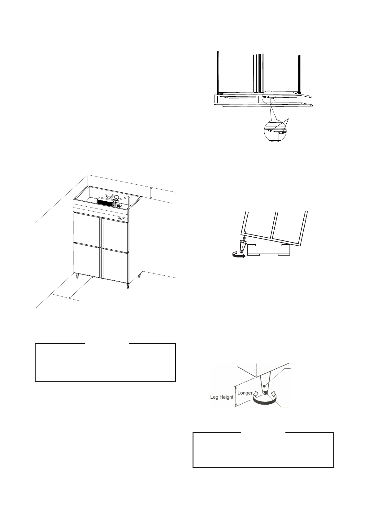
IMPORTANT
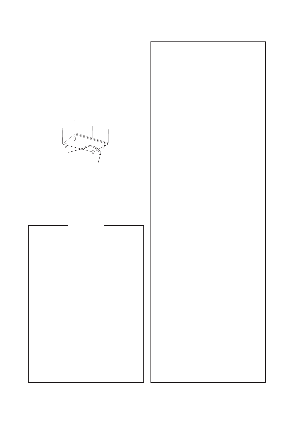
¬The drain outlet is at the bottom of the body. Use
the accessory to connect the drain hose.
1) Insert the 18 mm diameter end of flexible hose
into the defrost water drain outlet, and fix the
flexible hose with the accessory drain hose
band.
2) Attach the other end (26 mm outer diameter) of
the flexible hose to the drainage.
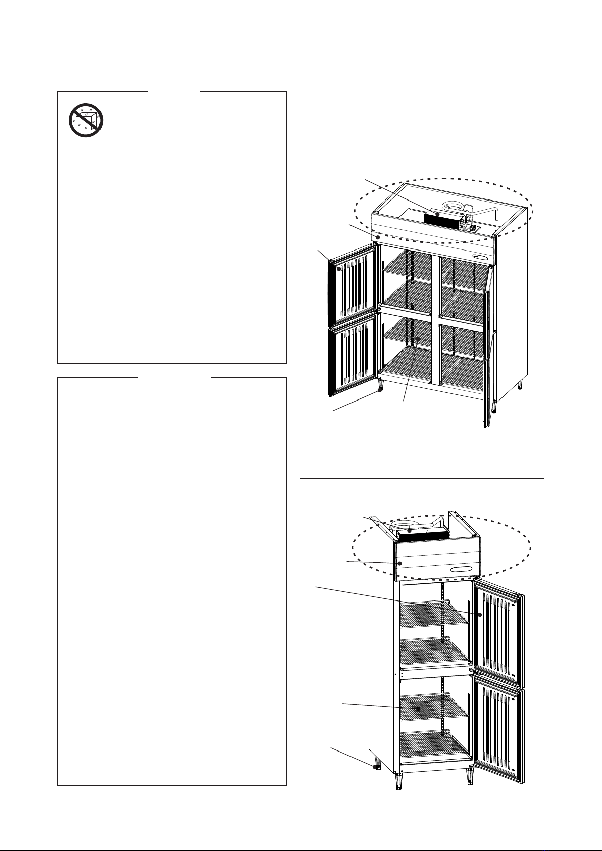
II. OPERATING INSTRUCTIONS
Fig. 12
8. Do not store bottles or cans near the air
outlet. They may freeze up and break,
causing a risk of injury.
9. Do not use combustible spray or place
volatile and flammable substances near the
unit. They could catch fire from a spark of a
switch or the like.
10. Do not put anything into the machine
compartment or the air inlet/outlet. The fan
rotating rapidly inside may cause injury or
heat.
11. Energies the for 1 hour and check for
proper temperature before putting foods in
the cabinet.
12. Do not block the air inlet/outlet with foods.
13. Do not pack the cabinet with foods. Allow
some space between them to ensure a
good air flow.
14. Do not put in warm or hot foods. Let them
cool first, or they will raise the cabinet
temperature and could deteriorate other
foods in the cabinet or overload the
refrigerator/freezer.
15. Make sure all items are snug on each shelf.
16. Moist or fresh foods and those with a strong
smell like seafood should be wrapped up
in a plastic film or packed in a container.
Otherwise the foods may dry up or give their
smells to other foods.
17.Foods containing acetic acid or yeast
should be wrapped up in a plastic film.
Otherwise they may accelerate corrosion of
the evaporator and copper tubes, resulting
in failure.
18. Foods intended for direct human
consumption should be stored on the shelf
in a proper container and protected from
direct contact with the cabinet walls.
19. Do not use the freezer to freeze foods. It is
designed only to store frozen foods. High
quality ice cream may melt during defrost
cycle and should not be stored in the
freezer.
20. The doors may become difficult to open
just after closed because of the negative
pressure created inside the cabinet. Wait for
about 30 seconds.
¬The drain hose may not be provided for some
models. If necessary, connect the optional drain
hose (1508117) to the 18 mm outer diameter drain
outlet located on the bottom rear of the unit.
8
Flexible Hose 700mm long
(end: 26mm outer diameter)
Defrost Water Drain Outlet
(18 mm diameter)
 User manual")


 User manual")