Hoshizaki DBF-AS65WE-EU-HC User manual

DBF-AS65WE-EU-HC
L1B078221 (060721)
3-16 Minamiyakata, Sakae-cho, Toyoake, Aichi 470-1194 Japan
INSTRUCTION MANUAL
(original instructions)
NOTICE D’UTILISATION
(instructions traduites)
BEDIENUNGSANLEITUNG
(Übersetzung)
GEBRUIKSAANWIJZING
(vertaalde instructies)
MANUAL DE INSTRUCCIONES
(instrucciones traducidas)
MANUALE D’ISTRUZIONI
(traduzione)
AUTOMATIC DRAFT BEER DISPENSER
TIREUSE A BIERE AUTOMATIQUE
AUTOMATISCHE BIERZAPFANLAGE
AUTOMATISCHE BIERTAPINSTALLATIE
DISPENSADOR AUTOMÁTICO DE CERVEZA DE BARRIL
SPILLATORE DI BIRRA AUTOMATICO

ENGLISH IMPORTANT SAFETY INFORMATION .................................................................................................. 1
I. INSTALLATION INSTRUCTIONS ..................................................................................................... 3
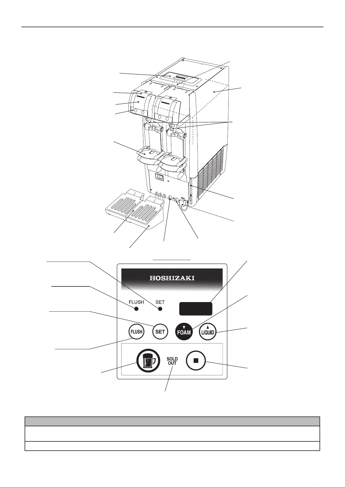
1. CONSTRUCTION ........................................................................................................................ 3
2. ACCESSORIES ........................................................................................................................... 4
3. UNPACKING................................................................................................................................ 4
4. LOCATION................................................................................................................................... 5
5. INSTALLATION............................................................................................................................ 5
[a] DISPENSER............................................................................................................................ 6
[b] DRAIN PAN............................................................................................................................. 6
[c] PLATFORM ADJUSTMENT.................................................................................................... 7
6. ELECTRICAL CONNECTIONS.................................................................................................... 9
7. GAS AND BEER CIRCUIT CONNECTIONS ............................................................................... 9
[a] CO2 GAS CYLINDER ............................................................................................................. 9
[b] HOSE CONNECTIONS ........................................................................................................ 10
[c] CHECKS AFTER CONNECTIONS ....................................................................................... 10
8. CHECKS AFTER INSTALLATION............................................................................................. 11
9. SOLD OUT SENSOR SETTING (“U07”).................................................................................... 11
10. USER SETTINGS ...................................................................................................................... 12
II. OPERATING INSTRUCTIONS........................................................................................................ 13
1. CLEANING BEER CIRCUIT....................................................................................................... 13
2. FILLING WATER TANK ............................................................................................................. 13
[a] HOW TO MAKE COOLING WATER..................................................................................... 13
[b] COOLING WATER SUPPLY................................................................................................. 14
3. CHECKS BEFORE OPERATION (DAILY)................................................................................. 14
[a] CHECKING CO2 GAS CYLINDER ....................................................................................... 14
[b] REPLACING CO2 GAS CYLINDER ..................................................................................... 14
[c] CHECKING BEER KEG ........................................................................................................ 15
[d] REPLACING BEER KEG ...................................................................................................... 15
4. START UP.................................................................................................................................. 16
[a] SWITCHING MODE.............................................................................................................. 16
[b] LEADING BEER TO TAP...................................................................................................... 16
5. SETTING LIQUID AND FOAM AMOUNTS................................................................................ 16
[a] LARGER MUG SETTING...................................................................................................... 17
[b] SMALLER MUG SETTING.................................................................................................... 17
6. DISPENSING ............................................................................................................................. 17
[a] AUTOMATIC DISPENSING.................................................................................................. 17
[b] STOPPING AUTOMATIC DISPENSING .............................................................................. 18
[c] MANUAL DISPENSING ........................................................................................................ 18
[d] SWITCHING TO AUTOMATIC DISPENSING MODE........................................................... 19
7. SOLD OUT SENSOR................................................................................................................. 19
8. END OF DISPENSING OPERATION ........................................................................................ 19
9. SHUT DOWN ............................................................................................................................. 19
[a] SHUT DOWN ........................................................................................................................ 19
[b] DRAINING WATER TANK .................................................................................................... 20
III. MAINTENANCE............................................................................................................................... 20
1. BASIC CLEANING ..................................................................................................................... 20
2. BEER CIRCUIT (DAILY) ............................................................................................................ 21
3. DRAIN PAN AND GRILLE (DAILY)............................................................................................ 22
4. PLATFORM (DAILY).................................................................................................................. 22
5. CLEANING BEER CIRCUIT WITH SPONGE (WEEKLY).......................................................... 23
6. DISASSEMBLY AND CLEANING OF BEER TAP (WEEKLY)................................................... 25
7. KEG COUPLER (WEEKLY)....................................................................................................... 26
8. EXTERIOR (WEEKLY)............................................................................................................... 26
9. AIR FILTER (BIWEEKLY) .......................................................................................................... 26
IV. INSPECTION................................................................................................................................... 26
1. COOLING WATER AND ELECTRODE (BIANNUALLY) ........................................................... 26
2. GAS HOSE AND BEER HOSE (MONTHLY)............................................................................. 27
3. ATTACHMENT PLUG AND POWER CORD (ANNUALLY / BIANNUALLY) ............................. 27
V. OTHER INFORMATION .................................................................................................................. 27
1. PREPARING THE DISPENSER FOR LONG STORAGE.......................................................... 27
2. BEFORE CALLING FOR SERVICE........................................................................................... 28
3. DISPOSAL ................................................................................................................................. 29
4. WARRANTY............................................................................................................................... 29
SPECIFICATIONS................................................................................................................................. 30

FRANCAIS INFORMATIONS IMPORTANTES RELATIVES A LA SECURITE ....................................................... 31
I. INSTRUCTIONS D’INSTALLATION................................................................................................ 33
1. COMPOSANTS.......................................................................................................................... 33
2. ACCESSOIRES ......................................................................................................................... 34
3. DEBALLAGE.............................................................................................................................. 34
4. EMPLACEMENT........................................................................................................................ 35
5. INSTALLATION.......................................................................................................................... 35
[a] TIREUSE............................................................................................................................... 36
[b] PLATEAU EGOUTTOIR........................................................................................................ 36
[c] REGLAGE DE LA PLATEFORME ........................................................................................ 37
6. BRANCHEMENTS ELECTRIQUES........................................................................................... 39
7. BRANCHEMENTS DES CIRCUITS DE GAZ ET DE BIERE..................................................... 39
[a] Bouteille de CO2 ................................................................................................................... 39
[b] RACCORDEMENTS DES TUYAUX ..................................................................................... 40
[c] CONTROLES A EFFECTUER APRES LES RACCORDEMENTS....................................... 41
8. CONTROLES A EFFECTUER APRES L’INSTALLATION ........................................................ 42
9. REGLAGE DU CAPTEUR DE FIN DE FUT (« U07 »)............................................................... 42
10. PARAMETRES UTILISATEUR .................................................................................................. 42
II. INSTRUCTIONS D’UTILISATION ................................................................................................... 43
1. NETTOYAGE DU CIRCUIT DE BIERE...................................................................................... 43
2. REMPLISSAGE DU RESERVOIR D’EAU ................................................................................. 44
[a] PREPARATION DE L’EAU DE RAFRAICHISSEMENT........................................................ 44
[b] ALIMENTATION EN EAU DE RAFRAICHISSEMENT.......................................................... 44
3. CONTROLES A EFFECTUER AVANT L’UTILISATION (AU QUOTIDIEN)............................... 45
[a] VERIFICATION DE LA BOUTEILLE DE CO2....................................................................... 45
[b] REMPLACEMENT DE LA BOUTEILLE DE CO2.................................................................. 45
[c] VERIFICATION DU FUT DE BIERE ..................................................................................... 45
[d] REMPLACEMENT DU FUT DE BIERE ................................................................................ 46
4. MISE EN MARCHE.................................................................................................................... 47
[a] MODE DE COMMUTATION ................................................................................................. 47
[b] POMPAGE DE LA BIERE VERS LE ROBINET.................................................................... 47
5. REGLAGE DES QUANTITES DE LIQUIDE ET DE MOUSSE .................................................. 47
[a] REGLAGE POUR GRANDE CHOPE ................................................................................... 48
[b] REGLAGE POUR PETITE CHOPE ...................................................................................... 48
6. TIRAGE...................................................................................................................................... 48
[a] TIRAGE AUTOMATIQUE...................................................................................................... 48
[b] ARRET DU TIRAGE AUTOMATIQUE .................................................................................. 49
[c] TIRAGE MANUEL ................................................................................................................. 49
[d] COMMUTATION VERS LE MODE DE TIRAGE AUTOMATIQUE ....................................... 50
7. CAPTEUR DE FIN DE FUT ....................................................................................................... 50
8. FIN DU TIRAGE......................................................................................................................... 50
9. ARRET ....................................................................................................................................... 51
[a] ARRET .................................................................................................................................. 51
[b] VIDANGE DU RESERVOIR D’EAU...................................................................................... 51
III. ENTRETIEN..................................................................................................................................... 51
1. NETTOYAGE DE BASE............................................................................................................. 52
2. CIRCUIT DE BIERE (AU QUOTIDIEN)...................................................................................... 52
3. PLATEAU EGOUTTOIR ET GRILLE (AU QUOTIDIEN)............................................................ 54
4. PLATEFORME (AU QUOTIDIEN).............................................................................................. 54
5.
NETTOYAGE DU CIRCUIT DE BIERE A L’AIDE DE L’EPONGE (UNE FOIS PAR SEMAINE)
.... 54
6. DEMONTAGE ET NETTOYAGE DU ROBINET DE BIERE (UNE FOIS PAR SEMAINE) ........ 57
7. RACCORD POUR FUT (UNE FOIS PAR SEMAINE)................................................................ 57
8. EXTERIEUR (UNE FOIS PAR SEMAINE)................................................................................. 58
9. FILTRE A AIR (TOUTES LES DEUX SEMAINES) .................................................................... 58
IV. INSPECTION................................................................................................................................... 58
1. EAU DE RAFRAICHISSEMENT ET ELECTRODE (DEUX FOIS PAR AN) .............................. 58
2. TUYAU DE GAZ ET TUYAU DE BIERE (UNE FOIS PAR MOIS) ............................................. 59
3. PRISE ET CORDON D’ALIMENTATION ELECTRIQUE (UNE A DEUX FOIS PAR AN).......... 59
V. INFORMATIONS DIVERSES .......................................................................................................... 59
1. PREPARATION DE LA TIREUSE EN VUE D’UN STOCKAGE PROLONGE ........................... 59
2. AVANT D’APPELER UN REPARATEUR................................................................................... 60
3. MISE AU REBUT ....................................................................................................................... 61
4. GARANTIE................................................................................................................................. 61
CARACTERISTIQUES.......................................................................................................................... 62

DEUTSCH WICHTIGE SICHERHEITSHINWEISE.................................................................................................. 63
I. INSTALLATIONSANWEISUNGEN.................................................................................................. 65
1. KOMPONENTEN ....................................................................................................................... 65
2. ZUBEHÖR.................................................................................................................................. 66
3. AUSPACKEN ............................................................................................................................. 66
4. STANDORT................................................................................................................................ 67
5. AUFSTELLUNG ......................................................................................................................... 67
[a] ZAPFANLAGE....................................................................................................................... 68
[b] ABTROPFSCHALE............................................................................................................... 68
[c] JUSTIERUNG DER PLATTFORM ........................................................................................ 69
6. ELEKTRISCHE ANSCHLÜSSE................................................................................................. 71
7. ANSCHLUSS VON GAS- UND BIERKREISLAUF..................................................................... 71
[a] CO2-PATRONE .................................................................................................................... 71
[b] SCHLAUCHVERBINDUNGEN.............................................................................................. 72
[c] KONTROLLE NACH DER VERBINDUNG............................................................................ 73
8. KONTROLLE NACH DER INSTALLATION ............................................................................... 73
9. EINSTELLUNG DES AUSVERKAUFT-SENSORS („U07“) ....................................................... 74
10. BENUTZEREINSTELLUNGEN.................................................................................................. 74
II. BETRIEBSANWEISUNGEN............................................................................................................ 75
1. REINIGUNG DES BIERKREISLAUFS....................................................................................... 75
2. WASSERTANK FÜLLEN ........................................................................................................... 75
[a] ERZEUGEN VON KÜHLWASSER ...................................................................................... 76
[b] KÜHLWASSERZUFUHR ...................................................................................................... 76
3. KONTROLLE VOR DEM BETRIEB (TÄGLICH) ........................................................................ 77
[a] CO2-PATRONE PRÜFEN..................................................................................................... 77
[b] CO2-PATRONE AUSTAUSCHEN ........................................................................................ 77
[c] BIERFASS PRÜFEN............................................................................................................. 78
[d] BIERFASS WECHSELN ....................................................................................................... 78
4. INBETRIEBNAHME ................................................................................................................... 79
[a] MODUSUMSCHALTUNG ..................................................................................................... 79
[b] FÖRDERN VON BIER ZUM ZAPFHAHN ............................................................................. 79
5. EINSTELLEN DER FLÜSSIGKEITS- UND SCHAUMMENGE .................................................. 79
[a] EINSTELLUNG FÜR DAS GRÖSSERE GLAS..................................................................... 80
[b] EINSTELLUNG FÜR DAS KLEINERE GLAS ....................................................................... 80
6. ZAPFEN ..................................................................................................................................... 80
[a] AUTOMATISCHE ABGABE.................................................................................................. 80
[b] AUTOMATISCHE ABGABE ANHALTEN.............................................................................. 81
[c] MANUELLE ABGABE ........................................................................................................... 81
[d] UMSCHALTEN IN DEN AUTOMATISCHEN ZAPFMODUS................................................. 82
7. AUSVERKAUFT-SENSOR ........................................................................................................ 82
8. ENDE DES ZAPFBETRIEBS..................................................................................................... 82
9. ABSCHALTEN ........................................................................................................................... 83
[a] ABSCHALTEN ...................................................................................................................... 83
[b] ENTLEEREN DES WASSERTANKS.................................................................................... 83
III. WARTUNG ...................................................................................................................................... 83
1. GRUNDLEGENDE REINIGUNG................................................................................................ 84
2. BIERKREISLAUF (TÄGLICH).................................................................................................... 84
3. ABTROPFSCHALE UND GITTER (TÄGLICH).......................................................................... 86
4. PLATTFORM (TÄGLICH)........................................................................................................... 86
5. REINIGEN DES BIERKREISLAUFS MIT EINEM SCHWAMM (WÖCHENTLICH).................... 86
6. AUSBAUEN UND REINIGEN DES ZAPFHAHNS (WÖCHENTLICH)....................................... 89
7. ZAPFKOPF (WÖCHENTLICH) .................................................................................................. 89
8. GEHÄUSE (WÖCHENTLICH).................................................................................................... 90
9. LUFTFILTER (ZWEIWÖCHENTLICH)....................................................................................... 90
IV. KONTROLLE ................................................................................................................................... 90
1. KÜHLWASSER UND ELEKTRODE (HALBJÄHRLICH) ............................................................ 90
2. GASSCHLAUCH UND BIERSCHLAUCH (MONATLICH) ......................................................... 91
3. STECKER UND NETZKABEL (JÄHRLICH/HALBJÄHRLICH)................................................... 91
V. WEITERE INFORMATIONEN ........................................................................................................ 91
1. VORBEREITEN DER ZAPFANLAGE FÜR EINE LÄNGERE LAGERUNG............................... 91
2. BEVOR SIE SICH AN DEN KUNDENDIENST WENDEN ......................................................... 92
3. ENTSORGUNG.......................................................................................................................... 93
4. GARANTIE................................................................................................................................. 93
TECHNISCHE DATEN.......................................................................................................................... 94

NEDERLANDS BELANGRIJKE VEILIGHEIDSINFORMATIE........................................................................................ 95
I. INSTALLATIE-INSTRUCTIES ......................................................................................................... 97
1. CONSTRUCTIE ......................................................................................................................... 97
2. ACCESSOIRES ......................................................................................................................... 98
3. UITPAKKEN............................................................................................................................... 98
4. LOCATIE.................................................................................................................................... 99
5. INSTALLATIE............................................................................................................................. 99
[a] TAP ..................................................................................................................................... 100
[b] LEKBAK .............................................................................................................................. 100
[c] PLATFORMINSTELLING.................................................................................................... 101
6. ELEKTRISCHE AANSLUITINGEN .......................................................................................... 103
7. AANSLUITINGEN VOOR GAS- EN BIERCIRCUIT................................................................. 103
[a] CO2-GASCILINDER ........................................................................................................... 103
[b] SLANGVERBINDINGEN..................................................................................................... 104
[c] CONTROLES NA VERBINDINGEN.................................................................................... 105
8. CONTROLES NA INSTALLATIE ............................................................................................. 105
9. INSTELLEN VAN DE UITVERKOCHTSENSOR (‘U07’).......................................................... 106
10. GEBRUIKERSINSTELLINGEN................................................................................................ 106
II. BEDIENINGSINSTRUCTIES......................................................................................................... 107
1. BIERCIRCUIT REINIGEN........................................................................................................ 107
2. WATERTANK VULLEN............................................................................................................ 107
[a] KOELWATER MAKEN........................................................................................................ 107
[b] KOELWATERTOEVOER .................................................................................................... 108
3. CONTROLES VOOR GEBRUIK (DAGELIJKS)....................................................................... 108
[a] CONTROLE VAN CO2-GASCILINDER.............................................................................. 108
[b] VERVANGING VAN CO2-GASCILINDER.......................................................................... 109
[c] BIERVAT CONTROLEREN................................................................................................. 109
[d] BIERVAT VERVANGEN ..................................................................................................... 109
4. OPSTARTEN ........................................................................................................................... 110
[a] SCHAKELMODUS .............................................................................................................. 111
[b] BIER NAAR DE TAP LEIDEN............................................................................................. 111
5. VLOEISTOF- EN SCHUIMHOEVEELHEID INSTELLEN......................................................... 111
[a] INSTELLING VOOR GROTE PUL...................................................................................... 112
[b] INSTELLING VOOR KLEINE PUL...................................................................................... 112
6. TAPPEN................................................................................................................................... 112
[a] AUTOMATISCH TAPPEN................................................................................................... 112
[b] AUTOMATISCH TAPPEN STOPPEN................................................................................. 113
[c] HANDMATIG TAPPEN........................................................................................................ 113
[d] OVERSCHAKELEN OP DE AUTOMATISCHE TAPMODUS ............................................. 113
7. UITVERKOCHTSENSOR ........................................................................................................ 114
8. EINDE VAN HET TAPPEN ...................................................................................................... 114
9. UITSCHAKELEN...................................................................................................................... 114
[a] UITSCHAKELEN................................................................................................................. 114
[b] AFTAPPEN VAN DE WATERTANK ................................................................................... 114
III. ONDERHOUD ............................................................................................................................... 115
1. BASISREINIGING.................................................................................................................... 115
2. BIERCIRCUIT (DAGELIJKS) ................................................................................................... 116
3. LEKBAK EN ROOSTER (DAGELIJKS) ................................................................................... 117
4. PLATFORM (DAGELIJKS)....................................................................................................... 117
5. BIERCIRCUIT REINIGEN MET EEN SPONS (WEKELIJKS).................................................. 118
6. BIERTAP UIT ELKAAR HALEN EN REINIGEN (WEKELIJKS)............................................... 120
7. TAPKOP (WEKELIJKS) ........................................................................................................... 121
8. BUITENKANT (WEKELIJKS)................................................................................................... 121
9. LUCHTFILTER (ELKE TWEE WEKEN)................................................................................... 121
IV. INSPECTIE.................................................................................................................................... 121
1. KOELWATER EN ELEKTRODE (TWEEMAAL PER JAAR).................................................... 121
2. GASSLANG EN BIERSLANG (MAANDELIJKS)...................................................................... 122
3. STEKKER EN NETSNOER (EEN-/TWEEMAAL PER JAAR).................................................. 122
V. OVERIGE INFORMATIE ............................................................................................................... 122
1. DE TAP VOORBEREIDEN OP LANGDURIGE OPSLAG........................................................ 122
2. VOORDAT U BELT VOOR SERVICE...................................................................................... 123
3. AFVOEREN.............................................................................................................................. 124
4. GARANTIE............................................................................................................................... 124
SPECIFICATIES.................................................................................................................................. 125

ESPAÑOL INFORMACIÓN DE SEGURIDAD IMPORTANTE.............................................................................. 126
I. INSTRUCCIONES DE INSTALACIÓN .......................................................................................... 128
1. ESTRUCTURA......................................................................................................................... 128
2. ACCESORIOS ......................................................................................................................... 129
3. DESEMBALAJE ....................................................................................................................... 129
4. UBICACIÓN ............................................................................................................................. 130
5. INSTALACIÓN ......................................................................................................................... 130
[a] DISPENSADOR .................................................................................................................. 131
[b] BANDEJA DE DRENAJE.................................................................................................... 131
[c] AJUSTE DE LA PLATAFORMA.......................................................................................... 132
6. CONEXIONES ELÉCTRICAS.................................................................................................. 134
7. CONEXIONES DEL CIRCUITO DE GAS Y CERVEZA........................................................... 134
[a] BOTELLA DE CO2.............................................................................................................. 134
[b] CONEXIONES DEL TUBO ................................................................................................ 135
[c] COMPROBACIONES UNA VEZ REALIZADAS LAS CONEXIONES................................. 136
8. COMPROBACIONES DESPUÉS DE LA INSTALACIÓN........................................................ 136
9. CONFIGURACIÓN DEL SENSOR DE CERVEZA AGOTADA (“U07”).................................... 137
10. AJUSTES DE USUARIO.......................................................................................................... 137
II. INSTRUCCIONES DE FUNCIONAMIENTO ................................................................................. 138
1. LIMPIEZA DEL CIRCUITO DE CERVEZA............................................................................... 138
2. LLENADO DEL DEPÓSITO DE AGUA.................................................................................... 139
[a] CÓMO CREAR AGUA DE REFRIGERACIÓN ................................................................... 139
[b] SUMINISTRO DE AGUA DE REFRIGERACIÓN................................................................ 139
3. COMPROBACIONES ANTES DE LA UTILIZACIÓN (DIARIAMENTE)................................... 140
[a] COMPROBAR LA BOTELLA DE CO2................................................................................ 140
[b] SUSTITUIR LA BOTELLA DE CO2 .................................................................................... 140
[c] COMPROBACIÓN DEL BARRIL DE CERVEZA................................................................. 141
[d] CAMBIAR EL BARRIL DE CERVEZA................................................................................. 141
4. PUESTA EN MARCHA ............................................................................................................ 142
[a] MODO DE CONMUTACIÓN............................................................................................... 142
[b] HACER LLEGAR LA CERVEZA AL GRIFO ....................................................................... 142
5. CONFIGURACIÓN DE LAS CANTIDADES DE LÍQUIDO Y ESPUMA ................................... 142
[a] CONFIGURACIÓN PARA JARRAS GRANDES................................................................. 143
[b] CONFIGURACIÓN PARA JARRAS PEQUEÑAS............................................................... 143
6. DISPENSAR............................................................................................................................. 143
[a] DISPENSACIÓN AUTOMÁTICA......................................................................................... 143
[b] DETENER LA DISPENSACIÓN AUTOMÁTICA................................................................. 144
[c] DISPENSACIÓN MANUAL ................................................................................................. 144
[d] CAMBIAR AL MODO DE DISPENSACIÓN AUTOMÁTICA................................................ 145
7. SENSOR DE CERVEZA AGOTADA........................................................................................ 145
8. FINAL DE LA OPERACIÓN DE DISPENSACIÓN................................................................... 145
9. DESCONEXIÓN....................................................................................................................... 146
[a] DESCONEXIÓN.................................................................................................................. 146
[b] DRENAJE DEL DEPÓSITO DE AGUA............................................................................... 146
III. MANTENIMIENTO......................................................................................................................... 146
1. LIMPIEZA BÁSICA................................................................................................................... 146
2. CIRCUITO DE CERVEZA (DIARIAMENTE)............................................................................ 147
3. BANDEJA DE DRENAJE Y REJILLA (DIARIAMENTE) .......................................................... 149
4. PLATAFORMA (DIARIAMENTE)............................................................................................. 149
5. LIMPIAR EL CIRCUITO DE CERVEZA CON UNA ESPONJA (SEMANALMENTE)............... 149
6. DESMONTAJE Y LIMPIEZA DEL GRIFO DE CERVEZA (SEMANALMENTE) ...................... 151
7. ACOPLADOR DEL BARRIL (SEMANALMENTE).................................................................... 152
8. PARTE EXTERIOR (SEMANALMENTE)................................................................................. 152
9. FILTRO DE AIRE (CADA DOS SEMANAS) ............................................................................ 153
IV. INSPECCIÓN................................................................................................................................. 153
1. AGUA DE REFRIGERACIÓN Y ELECTRODO (DOS VECES AL AÑO)................................. 153
2. TUBO DE GAS Y TUBO DE CERVEZA (UNA VEZ AL MES) ................................................. 154
3. ENCHUFE Y CABLE DE ALIMENTACIÓN (UNA VEZ AL AÑO/DOS VECES AL AÑO) ........ 154
V. OTRAS INFORMACIONES ............................................................................................................ 154
1. PREPARAR EL DISPENSADOR PARA UN ALMACENAMIENTO PROLONGADO .............. 154
2. ANTES DE LLAMAR AL SERVICIO TÉCNICO ....................................................................... 155
3. ELIMINACIÓN.......................................................................................................................... 156
4. GARANTÍA............................................................................................................................... 156
ESPECIFICACIONES ......................................................................................................................... 157

ITALIANO INFORMAZIONI IMPORTANTI SULLA SICUREZZA ......................................................................... 158
I. ISTRUZIONI DI INSTALLAZIONE................................................................................................. 160
1. STRUTTURA............................................................................................................................ 160
2. ACCESSORI ............................................................................................................................ 161
3. DISIMBALLAGGIO................................................................................................................... 161
4. UBICAZIONE ........................................................................................................................... 162
5. INSTALLAZIONE ..................................................................................................................... 162
[a] SPILLATORE ...................................................................................................................... 163
[b] VASSOIO DI SCARICO ...................................................................................................... 163
[c] REGOLAZIONE DELLA PIATTAFORMA............................................................................ 164
6. COLLEGAMENTI ELETTRICI.................................................................................................. 166
7. CONNESSIONI DEL GAS E DEL CIRCUITO DELLA BIRRA ................................................. 166
[a] BOMBOLA DI GAS CO2..................................................................................................... 166
[b] COLLEGAMENTI DEI TUBI................................................................................................ 167
[c] CONTROLLI DOPO I COLLEGAMENTI ............................................................................. 168
8. CONTROLLI DOPO L’INSTALLAZIONE ................................................................................. 168
9. IMPOSTAZIONI DEL SENSORE DI FINE DISPONIBILITÀ (“U07”)........................................ 169
10. IMPOSTAZIONI UTENTE ........................................................................................................ 169
II. ISTRUZIONI DI FUNZIONAMENTO.............................................................................................. 170
1. PULIZIA DEL CIRCUITO DELLA BIRRA................................................................................. 170
2. RIEMPIMENTO DEL SERBATOIO DELL’ACQUA .................................................................. 170
[a] COME PREPARARE L’ACQUA DI RAFFREDDAMENTO ................................................. 171
[b] APPROVVIGIONAMENTO DELL’ACQUA DI RAFFREDDAMENTO ................................. 171
3. CONTROLLI PRIMA DELL’USO (TUTTI I GIORNI) ................................................................ 172
[a] CONTROLLO DELLA BOMBOLA DI GAS CO2 ................................................................. 172
[b] SOSTITUZIONE DELLA BOMBOLA DI GAS CO2............................................................. 172
[c] CONTROLLO DEL FUSTO DELLA BIRRA......................................................................... 173
[d] SOSTITUZIONE DEL FUSTO DELLA BIRRA .................................................................... 173
4. AVVIO ...................................................................................................................................... 174
[a] CAMBIO DI MODALITÀ ...................................................................................................... 174
[b] FAR ARRIVARE LA BIRRA AL RUBINETTO ..................................................................... 174
5. IMPOSTAZIONE DELLE QUANTITÀ DI LIQUIDO E SCHIUMA ............................................. 174
[a] IMPOSTAZIONE BOCCALE GRANDE............................................................................... 175
[b] IMPOSTAZIONE BOCCALE PICCOLO.............................................................................. 175
6. EROGAZIONE ......................................................................................................................... 175
[a] EROGAZIONE AUTOMATICA............................................................................................ 175
[b] INTERRUZIONE DELL’EROGAZIONE AUTOMATICA...................................................... 176
[c] EROGAZIONE MANUALE .................................................................................................. 176
[d] PASSAGGIO ALLA MODALITÀ EROGAZIONE AUTOMATICA ........................................ 177
7. SENSORE DI FINE DISPONIBILITÀ ....................................................................................... 177
8. FINE DELL’EROGAZIONE ...................................................................................................... 177
9. SPEGNIMENTO....................................................................................................................... 178
[a] SPEGNIMENTO.................................................................................................................. 178
[b] SVUOTAMENTO DEL SERBATOIO DELL’ACQUA........................................................... 178
III. MANUTENZIONE .......................................................................................................................... 178
1. PULIZIA DI BASE.....................................................................................................................178
2. CIRCUITO DELLA BIRRA (TUTTI I GIORNI) .......................................................................... 179
3. VASSOIO DI SCARICO E GRIGLIA (TUTTI I GIORNI)........................................................... 181
4. PIATTAFORMA (TUTTI I GIORNI) .......................................................................................... 181
5.
PULIZIA DEL CIRCUITO DELLA BIRRA CON LA SPUGNA (UNA VOLTA ALLA SETTIMANA)
.... 181
6.
SMONTAGGIO E PULIZIA DEL RUBINETTO DELLA BIRRA (UNA VOLTA ALLA SETTIMANA)
... 184
7. INNESTO DEL FUSTO (UNA VOLTA ALLA SETTIMANA)..................................................... 184
8. ESTERNO (UNA VOLTA ALLA SETTIMANA)......................................................................... 185
9. FILTRO DELL’ARIA (OGNI DUE SETTIMANE)....................................................................... 185
IV. ISPEZIONE....................................................................................................................................185
1. ACQUA DI RAFFREDDAMENTO ED ELETTRODO (DUE VOLTE L’ANNO)......................... 185
2. TUBO DEL GAS E TUBO DELLA BIRRA (UNA VOLTA AL MESE)........................................ 186
3. SPINA ELETTRICA E CAVO DI ALIMENTAZIONE (UNA VOLTA/DUE VOLTE L’ANNO) ..... 186
V. ALTRE INFORMAZIONI ................................................................................................................ 186
1. PREPARAZIONE DELL’EROGATORE PER UNA CONSERVAZIONE PROLUNGATA ........ 186
2. PRIMA DI RICHIEDERE L’INTERVENTO DEL SERVIZIO DI ASSISTENZA ......................... 187
3. SMALTIMENTO ....................................................................................................................... 188
4. GARANZIA............................................................................................................................... 188
SPECIFICHE.......................................................................................................................................189

1
ENGLISH
IMPORTANT SAFETY INFORMATION
Throughout this manual, notices appear to bring your attention to situations which could result in
death, serious injury, or damage to the unit.
WARNING Indicates a hazardous situation which, if not avoided, could result in death or
serious injury.
CAUTION Indicates a hazardous situation which, if not avoided, could result in minor or
moderate injury.
NOTICE Indicates a hazardous situation which, if not avoided, could result in damage to
the unit.
HYGIENE Indicates important precautions for hygiene and food safety.
IMPORTANT Indicates important information about the use and care of the unit.
This automatic draft beer dispenser uses HFC-free refrigerant (isobutane) and HFC-free foam
insulation that are non-ozone-depleting and environmentally sustainable materials having very
low global warming potential.
WARNING
This automatic draft beer dispenser contains flammable refrigerant in its cooling unit;
installation, handling, servicing and disposal must therefore only be carried out by authorized
technicians.
The refrigerant contained in this automatic draft beer dispenser is flammable and sealed
in the refrigeration system. Although the refrigerant does not leak out under normal usage,
take utmost care when handling this automatic draft beer dispenser so as not to cause any
damages to the system.
In the case of accidental damage to the refrigeration system causing refrigerant leak:
* Do not create a source of ignition in the area.
* Do not operate electrical switches or plugs in the area.
*Donotusenakedame.
* Immediately ventilate the area by opening doors and/or windows.
* Call service engineer.
IMPORTANT
This booklet is an integral and essential part of the product and should be kept and preserved
by the user.
Please read carefully the guidelines and warnings contained herein as they are intended to
provide the installer/user with essential information for the proper installation and the continued
safe use and maintenance of the product.
Please preserve this booklet for any further consultation that may be necessary.

2
ENGLISH
WARNING
This is a commercial automatic draft beer dispenser, and should be destined only to be used
for the purpose for which it has been expressly designed.
Any other use should be considered improper and therefore dangerous. The manufacturer
will not be held liable or responsible for any damage caused by improper, incorrect and
unreasonable use.
The installation, and relocation if necessary, must be carried out by qualied personnel,
in accordance with current regulations, according to the manufacturer’s instructions.
Keep ventilation openings, in the appliance enclosure or in the built-in structure, clear of
obstruction.
Do not damage the refrigerating circuit.
The maintenance operations must be conducted by trained person. Access to the service
area is restricted to persons having knowledge and practical experience of the appliance, in
particular as far as safety and hygiene are concerned.
The use of any electrical appliance involves the observance of some fundamental rules. In
particular:
*Instances of high humidity and moisture increase the risk of electrical short circuits and
potential electrical shocks. If in doubt, disconnect the dispenser.
*Do not damage the power cord or pull it in order to disconnect the dispenser from the
electrical supply network.
*If the supply cord and/or the plug should need to be replaced, it should only be done by a
qualiedserviceengineer.
*Do not touch the electrical parts or operate the switches with damp hands.
*This appliance is not intended for use by persons (including children) with reduced physical,
sensory or mental capabilities, or lack of experience and knowledge, it can however be used
by children aged from 8 years and above and persons with reduced physical, sensory or
mental capabilities, or lack of experience and knowledge providing they have been given
supervision or instruction concerning use of the appliance by a person responsible for their
safety.
*Children shall not play with the appliance.
*Cleaning and user maintenance shall not be made by children without supervision.
*Donotattempttomodifythedispenser.Onlyqualiedpersonnelmaydisassembleorrepair
the appliance.
When positioning the appliance, ensure the supply cord is not trapped or damaged.
Do not locate multiple portable socket-outlets or portable power supplies at the rear of the
appliance.
The meaning of this ISO 7010 W021 symbol is:
Warning:Riskofre

3
ENGLISH
I. INSTALLATION INSTRUCTIONS
1. CONSTRUCTION
NOTICE
Open the panel cover to access the buttons and lamps other than the dispense button (dispense lamp), sold out lamp and
stop button.
To prevent damage to the panel cover, do not open it by force.
Operation Panel
Tank Cover
Water Tank
Operation Panel Unit
Platform (Accessory)
Grille (Accessory)
Beer Tap
Air Filter
Drain Outlet
Beer Inlet (Right)
Beer Inlet (Left)
Water Level Line (Label)
Drain Pan (Accessory)
Panel Cover
Operation Panel
Sold Out Lamp
Lights up when the keg becomes empty.
Flush Lamp
Lights up when the dispenser is
intheushmode.
Flush Button
Switches between the ready
modeandushmode.
Dispense Button (Dispense Lamp)
Lights up when the dispenser is in the ready mode.
[Press once]
Automatically dispenses the preset amount of beer.
[Press and hold]
Makes the automatic dispensing settings available
while in the setting mode.
Stop Button
[Press once]
Manually stops the beer tap or platform
operation.
[Press and hold]
Resets the display indication (e.g.
number of mugs).
Foam Button
[In ready mode]
Press and hold to dispense foam.
[In ush mode]
Press once to dispense foam. Press
again to stop.
Liquid Button
[In ready mode]
Press and hold to dispense liquid.
[In ush mode]
Press once to dispense liquid. Press
again to stop.
Set Lamp
Lights up when the dispenser is
in the setting mode.
Display
Indicates number of mugs and so on.
Set Button
[Press once]
Switches between the setting mode and ready
mode(dispenselampashesrapidly).
[Press and hold]
Used to make user settings (“U_ _” on display).

4
ENGLISH
Prepare and install the following equipment. Consult with the liquor shop, beer company or distributor to prepare the regulator,
keg coupler and CO2 gas cylinder designed for the beer to dispense.
[1] CO2 Gas Cylinder
[2] Regulator
[3] Keg Coupler
[4] Quick Beer Hose Joint (Coupler Side)
[5] Quick Beer Hose Joint (Dispenser Side)
[6] Quick Gas Hose Joint (Regulator Side)
[7] Quick Gas Hose Joint (Coupler Side)
[8] Y-Tee
[9] Gas Hose (Short)
[10] Gas Hose (Long)
[11] Beer Hose
[12] Beer Keg
[13] Cleaning Tank
[14] Hook (Accessory)
[15] Cylinder Chain (Accessory)
2. ACCESSORIES
Instruction Manual 1
Instruction Sheet 1
Drain Pan 2
Nozzle Cap 8
Brush 1
Brush (S) 1
Cleaning Sponge 6
Instruction Label 1
Platform Assembling
Instructions 1
Spanner 1
Hook 1
Hook Mounting Screw 2
Cylinder Chain 1
O-Ring (L) P21 1
Grille 2
Platform 2
3. UNPACKING
WARNING
Children should not be allowed in reach of the packaging elements (plastic bags and expanded polystyrene) as they are
potential sources of danger.
CAUTION
Do not lift or manoeuvre the carton by using the shipping bands.
When moving the unit by hand, hold the unit bottom.
Do not hold the beer tap to lift up the unit. The beer tap may be damaged or the unit may fall causing injury.
Always wear protective gloves when carrying the unit.
When handling the carton or the unpacked unit, work in pair to prevent injury.
Instruction Manual Instruction Sheet Drain Pan Nozzle Cap Brush (S)Brush
Cleaning Sponge Instruction Label Platform Assembling Instructions HookSpanner
Hook Mounting Screw Cylinder Chain O-Ring (L) P21 Grille Platform

5
ENGLISH
NOTICE
Remove shipping carton, tape(s) and packing. If packing material is left in the dispenser, it will not work properly.
To prevent damage, do not tilt the dispenser more than 45°.
1) After removing the packaging, make sure that the dispenser is in good condition. If in doubt, please do not use the dispenser
butapplytoprofessionallyqualiedpersonnel.
2)Removetheprotectiveplasticlmfromtheexterior.Ifthedispenserisexposedtothesunortoheat,removethelmafterthe
dispenser cools.
3) Remove the package of accessories. Check the contents according to “2. ACCESSORIES”.
4. LOCATION
WARNING
This dispenser is not intended for outdoor use.
The dispenser should not be located next to ovens, grills or other high heat producing equipment.
This appliance is not suitable for installation in an area where a water jet could be used.
CAUTION
Thelocationshouldprovidearmandlevelfoundationforthedispenser.
NOTICE
Do not place anything to obstruct the ventilation louvers.
IMPORTANT
Normal operating ambient temperature should be within 5°C to 32°C, cooling water temperature not more than 25°C, and beer
keg temperature within 10°C to 30°C. Operation of the dispenser, for extended periods, outside of these normal temperature
rangesmayaectproductioncapacity.
Allow 10 mm extra space at the installation site to meet any installation requirements (additional spacing is also required for
properairowandpipeconnections).
Keep the dispenser away from direct sunlight.
Allowtheclearancespeciedbelowforproperaircirculationand
ease of maintenance and/or service should they be required.
Insomehighhumidityenvironments,condensationmayforminsidethemachineanddripontotheoor.Donotinstallwhere
theoorcanbeaectedbywater.
Avoid prolonged exposure of the appliance to direct sunlight.
5. INSTALLATION
CAUTION
Incorrect installation can cause harm to people, animals or other items, for which the manufacturer cannot be held
responsible.
Min 50 mm
Min 510 mm
Front Min 100 mm
Min 50 mm
AirAir
Air

6
ENGLISH
[a] DISPENSER
The front rubber feet can be moved backward from their original position. If the feet
cannottwithintheinstallationspaceonthecounterortable,useascrewdriverto
removethefrontfeetfromthebottomandretatthefollowingpositions.
Factory Setting Distance: A 274 mm
Distance: B 388 mm
After Adjustment Distance: a 244 mm
Distance: b 328 mm
[b] DRAIN PAN
To attach the drain pan (accessory) and grille (accessory):
(1) lift up the front of the drain pan,
(2) push the drain pan securely into the drain pan support, and
(3) push down the front of the drain pan.
Do not tilt more than 1 cm
Distance: b
Distance: B
Rubber Foot
Distance: a
Distance: A
After installation of accessories
(2) Push in
(1) Lift up front
Grille
Drain Pan
Drain Pan
(3) Push down front

7
ENGLISH
[c] PLATFORM ADJUSTMENT
Theupperandlowerplatformpositionsareadjustabletoaccommodatetwodierentmugheights.Theguidecanalsobemoved
back and forth according to the mug shape.
1) The platform assembly has the components as
shown on the right.
2) Move the platform in the desired position and secure it with the screws.
The upper platform position is adjustable between the 1st and 7th levels of the mug
plate, and the lower platform position between the 4th and 12th levels. The top of
themugmusttthemarkonthebackplatewhenpositionedontheplatform.(See
the table on the next page for the mug heights and platform positions.)
3)Afteradjustingtheplatformpositions,ttheguidetopositionthebottomofthe
mug. The guide with cover is for the upper platform.
4)Rettheplatformstotheunit.
NOTICE
When adjusting the upper platform position, also adjust the bracket position according to the table on the next page.
Mug Plate
Upper Platform
Built-in
Sensor
Magnet
Lower Platform
Mark
Back
Plate
Screw
Front Rear
Remove screws
on both sides
Shift
Guide
Cover
Hook
(2)Ret
(1) Adjust position
(3) Secure with screws
on both sides

8
ENGLISH
Mug Plate Level Upper Platform Lower Platform
Mounting Hole Mug Height (mm) Bracket Position Mounting Hole Mug Height (mm)
1Lower 135
ANot available
Upper 140
2Lower 145
Upper 150
3Lower 155
Upper 160
4Lower 165 Lower 155
Upper 170
B
Upper 160
5Lower 175 Lower 165
Upper 180 Upper 170
6Lower 185 Lower 175
Upper 190 Upper 180
7Lower 195 Lower 185
Upper 200 Upper 190
8
Not available
Lower 195
Upper 200
9Lower 205
Upper 210
10 Lower 215
Upper 220
11 Lower 225
Upper 230
12 Lower 235
Upper 240
Note:
1) Mug diameter: 50 mm inside diameter to 105 mm outside diameter and bottom diameter
2) The larger mug must be at least 20 mm higher than the smaller mug.
Bracket
Position: A (Factory Setting)
Position: B
Bracket PositionPlatform Position
1st Level
12th Level
Upper
Mounting
Hole
Lower
Mounting
Hole
Min 20 mm
Fit on boss

9
ENGLISH
6. ELECTRICAL CONNECTIONS
WARNING
THIS APPLIANCE MUST BE EARTHED
This dispenser requires an earth that meets the national and local electrical code requirements.
To prevent possible severe electrical shock to individuals or extensive damage to the unit, install a proper earth wire to the dispenser.
Remove the plug from the mains socket before any maintenance, repairs or cleaning is undertaken.
CAUTION
The maximum allowable voltage variation should not exceed ±10 percent of the rated voltage. Operation of the unit outside of
this range may cause smoking, ignition, damage to the unit or reduction of the performance.
* This appliance requires a separate power supply. The electrical supply must be protected by a suitable circuit breaker.
* Usually an electrical permit and services of a licensed electrician are required.
* If the supply cord is damaged, it must be replaced by a replacement cord available from your dealer/supplier.
7. GAS AND BEER CIRCUIT CONNECTIONS
[a] CO2 GAS CYLINDER
WARNING
Use a CO2 gas cylinder designed for use with beer. Use of any other cylinders may cause explosion or air pollution.
While carrying the CO2 gas cylinder, keep the cap closed and avoid any impact on the cylinder to prevent the risk of explosion
or gas leaks.
Keep the CO2 gas cylinder away from direct sunlight or temperatures above 40°C to avoid excessive temperature rise and
explosion.
The regulator must be provided with an undamaged gasket to prevent the risk of gas leaks. If not, contact the liquor shop,
beer company or distributor to install a new gasket.
Standthe CO2gas cylinderupright, andx itsecurely withthe accessorychain toprevent overturn resultingin injuryor
explosion.
KeepyourfaceawayfromtheCO2gascylinderwhileblowingdirtanddustotheregulatorjoint.Dustgettinginyoureyes
can cause visual impairment.
Handle the regulator with care to avoid any impact, or it may not work properly and the beer keg or hose can explode.
Before opening the main valve of the CO2 gas cylinder or removing the keg coupler from the beer keg, set the regulator to “0”.
Otherwise,suddenapplicationofgaspressureonthebeerkegmaycauseexplosionorblow-oofthekegcoupler.
1) Open the main valve of the new CO2 gas cylinder for a second to
blowdirtanddustothejoint(togetherwithCO2gas).
2) Check the regulator gasket. If it is damaged or not provided,
install a new gasket. (Contact the liquor shop, beer company or
distributor.)
3) Install the regulator securely on the CO2 gas cylinder.
NOTICE
Tightenthenutbyhandrst,thenwiththespanner(accessory)so
that the level gauge will be upright.
4) Open the main valve by turning it counterclockwise, and check the regulator nut for gas leak (sound). If gas is leaking, the nut
must be loose or the gasket must be damaged or not provided.
Note: To check for gas leaks, apply a sponge with soap to the joint. Bubbles form if gas is leaking.
Level Gauge
Nut
Main Valve
Regulator
Adjust Dial
Gasket
CO2 Gas Cylinder
*Theregulatordesignisdierent
for each beer company.

10
ENGLISH
[b] HOSE CONNECTIONS
WARNING
Topreventtheriskofgasleaksandhoseexplosion,donotuseanyhosesotherthanspeciedbythebeercompany.
Cut the hose end to have a vertical cutting plane and insert it securely into the quick hose joint to ensure a leak-free joint.
NOTICE
Do not reconnect the hoses without cutting them about 20 mm.
Cut the hoses with a specialized tool such as hose cutter. Do not use scissors, or the hoses may be crushed to cause leaks.
CO2 Gas Hose
1) Cut the CO2 gas hose to have a vertical cutting plane and a hose length not
more than 1.4 m.
2) Insert the CO2 gas hose securely into the quick gas hose joint on the keg
coupler and regulator. Pull the hose hard to check for tightness.
Quick Gas Hose Joint
1) To connect the CO2 gas hose, push it all
the way in.
2) To disconnect the CO2 gas hose, push
andholdpart(1)withngersandpullout
the hose (2).
Beer Hose
1)Attachthequick beerhosejoint speciedbythe beercompany tothebeer
hose adapter.
2) Cut the beer hose to have a vertical cutting plane and a hose length not more
than 2.1 m.
3) Insert the beer hose securely into the keg coupler and quick beer hose joint.
Pull the hose hard to check for tightness.
Note: It depends on the beer company how to connect and
disconnect the beer hose to and from the quick beer
hose joint.
[c] CHECKS AFTER CONNECTIONS
1)Washthecleaningtankthoroughlyandllitwithtapwater.
Note: If the cleaning tank is not clean, the beer circuit will be contaminated.
2) Turn the keg coupler clockwise to attach it to the cleaning tank.
Note: Wash the joint between the keg coupler and cleaning tank if it is not clean.
3) Lift up and remove the platform.
4) Place a bucket on the drain pan to receive cleaning water.
Keg Coupler Regulator
Rotary Type Vertical Type
Quick Gas Hose Joint Gas Hose
Push
(1) (2)
Beer Hose Adapter
Quick Beer Hose Joint
Beer Hose Keg Coupler
Rotary Type Vertical Type

11
ENGLISH
5) Check that the beer tap lever is in the closed (normal) position. Open the main
valve of the CO2 gas cylinder by turning it counterclockwise a few times.
6) Turn the regulator adjust dial to set the pressure to “0.15” (MPa).
7) Open the beer circuit.
Rotary type: Turn the keg coupler handle clockwise until it stops.
Vertical type: Push down the keg coupler handle until it locks in place.
Note: If the cleaning tank is provided with a siphon tube, lay the cleaning tank with the ferrule at the top. If not, lay the
cleaning tank with the ferrule at the bottom.
8) Pull the beer tap lever toward you to pour water out of the liquid nozzle.
9) Check the CO2 gas circuit for gas leaks. If it is leaking, correct the hose connections.
10) Check the beer circuit for water leaks. If it is leaking, correct the hose connections.
11) Keep the beer tap lever in the open position and turn the
regulator adjust dial to set the pressure to “0” (MPa).
12) Close the main valve of the CO2 gas cylinder by turning
it clockwise.
13) When CO2 gas stops coming out of the nozzle, push the
beer tap lever back to the closed position.
8. CHECKS AFTER INSTALLATION
1)Fillthewatertankwiththespeciedwater.See“II.2.FILLINGWATERTANK”.
2) Flush the beer circuit and check for water leaks. See “III. 2. BEER CIRCUIT (DAILY)”.
3) Check for proper power supply voltage.
4) Plug in the unit.
* Check that the refrigeration unit and agitator motor start.
(In low temperature conditions, the condenser fan motor may not start until the condenser temperature goes up.)
* After 8 to 13 hours (depending on ambient/water temperature), open the top cover and check that ice is stored in the water
tank.
5) Instruct the user on how to operate the unit.
6) Hand this instruction manual to the user.
9. SOLD OUT SENSOR SETTING (“U07”)
Choose among the four modes according to the type of beverage to dispense (e.g. beer, cocktail).
1) Lower the operation panel unit on the desired side.
2) Press and hold the set button on the operation panel to show “U01” on the display.
3) Use the foam button or liquid button to show “U07” on the display.
CO2 Gas Cylinder
Open
Lever
Closed Position
Siphon Tube
Provided Not provided
Keg Coupler Handle
Rotary Type Vertical Type
Bucket
Open Position
CO2 Gas Cylinder
Close
Lever
Closed Position

12
ENGLISH
4) Press the set button to show the current number on the display. Use the foam button or liquid button to choose the desired
number(seetablebelow).Pressthesetbuttontosettheashingnumber.
No. Setting
0 Setting A (mainly beer)
1 Setting B (mainly cocktail)
2 Setting C (mainly cocktail)
3 Setting D (optional)
Note: The sold out sensor is factory set to “0: Setting A (mainly beer)”. The setting depends on the brand of beverage to
dispense. Check with your dealer/supplier.
5) Press the set button again to show “U07” on the display. Press and hold the set button for more than 3 seconds to complete
the setting.
Note: If no operation is performed for more than 1 minute, the dispensing mode is resumed. In that case, go back to step 2)
above.
10. USER SETTINGS
To make or change settings:
Press and hold the set button for 3 seconds to enter the setting mode (see “9. SOLD OUT SENSOR SETTING (“U07”)”).
To complete settings:
With “U_ _” on the display, press and hold the set button for 3 seconds to enter the dispensing mode.
The dispensing mode is also resumed if no operation is performed for more than 1 minute.
Item Description Default Setting Range
U01 Digital display
(in dispensing mode)
0: No indication
1: Number of mugs (*)
* Number switches between the larger and smaller mugs when the mug
setting is changed.
* To reset, press and hold the stop button for 3 seconds.
0 0 - 1
U02 Log of number of mugs
Log of number of mugs for each reset in descending order
* Log is indicated in turn for each keg replacement by “U04”.
* Log is indicated for both larger and smaller mugs when the mug setting is
changed.
* To reset all the current and past logs, press and hold the stop button for
3 seconds. This reset is not counted for “U04”.
0 Up to 5 logs
U03 Numberofushcycles
Numberofushcyclesperformed
*Aushcycleconsists ofliquidbuttonoperation(total10seconds)+foam
button operation (total 3 seconds) in the flush mode except when no
automatic dispensing action is made during the cycle.
* To reset, press and hold the stop button for 3 seconds.
0 0 - 9999
U04
Number of keg
replacements
(reset frequency)
Reset frequency for number of mugs
* Keg replacement is counted every time the number of kegs is reset by the
stop button operation.
* To reset, press and hold the stop button for 3 seconds.
0 0 - 9999
U05 Dispense lamp
brightness Adjustment of dispense lamp brightness 6 1 - 8
U06 Dispenselampashing
duration
Adjustmentofdispense lampashingduration aftercompletionof
dispensing
*Thedispenselampashestopreventanothermugisplacedwhilefoamis
still dripping.
*Automaticdispensingactionisnotavailablewhilethelampisashing.
1 0 - 10
U07 Sold out sensor setting
0: Setting A (mainly beer) / threshold: 2.2V
1: Setting B (mainly cocktail) / threshold: 2.5V
2: Setting C (mainly cocktail) / threshold: 2.8V
3: Setting D (optional) / threshold: optional
* The setting depends on the brand of beverage to dispense. Check with your
dealer/supplier.
0 0 - 3

13
ENGLISH
U08 Self mode setting
0: No
1: Yes (no button operation is available except dispense/stop button)
* The self mode is reset when the manual dispensing mode is selected (by
lifting up the operation panel unit). To resume the self mode, switch to the
automatic dispensing mode (by pulling down the operation panel unit) and
press the dispense button.
0 0 - 1
U09 Mug tilting operation 0: Yes (mug is tilted while beer is being dispensed)
1: No (mug is kept upright while beer is being dispensed) 0 0 - 1
U10 Reset number of mugs 0: Manual
1: Manual or when sold out sensor detects
* To reset manually, press and hold the stop button for 3 seconds.
0 0 - 1
U90 Reset settings
Initialize only the user settings
* To initialize, with “1” shown on the display, press and hold the stop button
for 3 seconds.
* If the settings are updated, “U90” appears on the display. If not updated, “0”
appears again.
0 0 - 1
II. OPERATING INSTRUCTIONS
1. CLEANING BEER CIRCUIT
Although the beer circuit is cleaned before shipping, clean it again before use. See “III. 2. BEER CIRCUIT (DAILY)”.
Check that the parts are installed in their correct positions. See “I. 1. CONSTRUCTION”.
2. FILLING WATER TANK
NOTICE
Useonlythespeciedwatertollthewatertank.Useofanyotherwaterormixtureofsalt,vinegarorjuicemaycauseinsucient
ice storage, corrosion or perforation.
[a] HOW TO MAKE COOLING WATER
IMPORTANT
Carefullyreadthisbeforellingthewatertank.
Electric conductivity (E.C.) of cooling water for water tank
Do not use tap water.
Fillthewatertankwithwaterhaving100-300μS/cmofE.C.
Measure the electric conductivity with conductivity meter.
* E.C.: Physical property to show the ability of conducting electricity.
Unit:μS(microsiemens)/cm
Below100μS/cm:
Compressor may not work resulting in poor cooling performance.
Above300μS/cm:
Excessive ice may build up on evaporator and freeze beer inside beer coil preventing beer from
being dispensed properly.
How to make cooling water with 100-300 μS/cm of E.C.
The capacity of the water tank of this unit is approx. 30 L.
Make the cooling water by dissolving 5 g of pure baking soda in approx. 10 L of distilled water,
andthenaddapprox.20Lofdistilledwatertollthewatertank.
Step 1
Measure 5 g of pure baking soda with nozzle cap (accessory).
Step 2
Fill a bucket with approx. 10 L of distilled water and stir well after adding the 5 g of baking
soda measured in step 1.
Rinse the nozzle cap after use.
Nozzle Cap 5/6
(5 g)
Nozzle Cap
Distilled Water
(approx. 10 L)
Bucket
Table of contents
Languages:
Other Hoshizaki Kitchen Appliance manuals