Hoshizaki DBF-AS65WE-T User manual

DBF-AS65WE-T
L1B078101 (103119)
AUTOMATIC DRAFT BEER DISPENSER
INSTRUCTION MANUAL
3-16 Minamiyakata, Sakae-cho, Toyoake, Aichi 470-1194 Japan

IMPORTANT SAFETY INFORMATION ..........................................................................................................................................1
I. INSTALLATION INSTRUCTIONS .............................................................................................................................................2
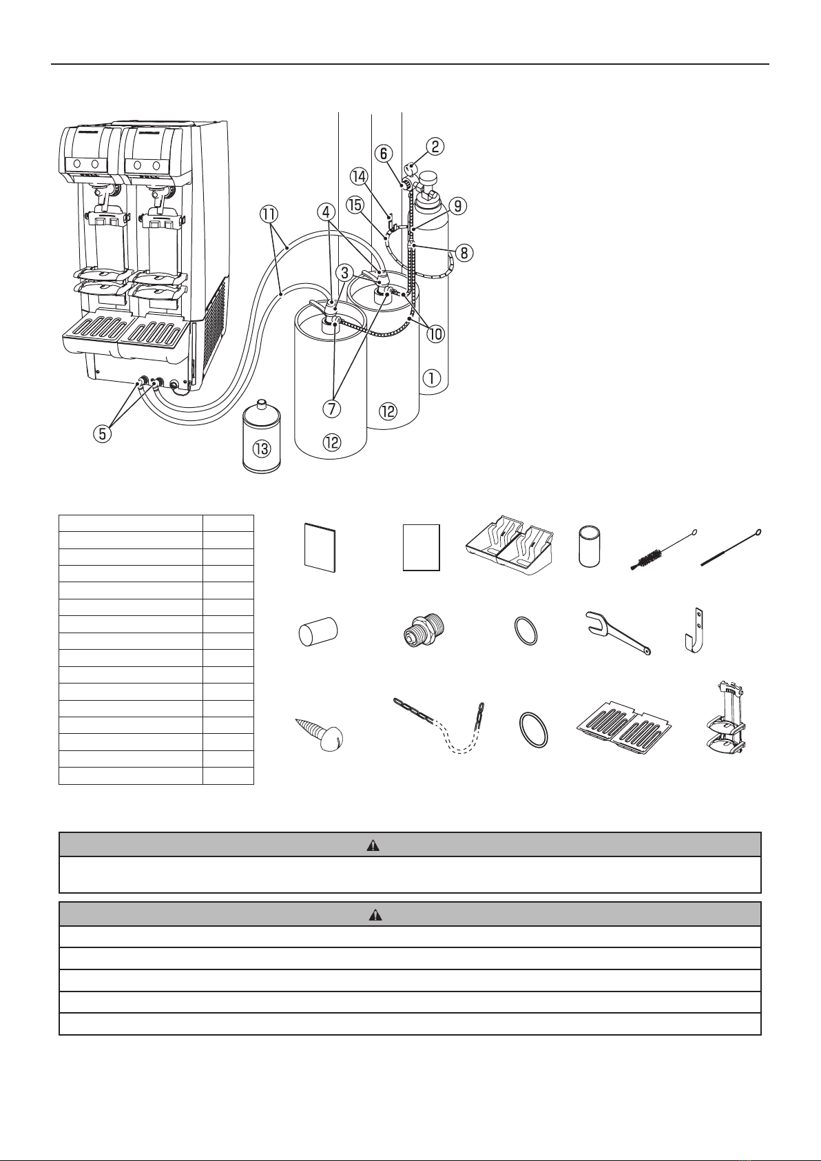
1. CONSTRUCTION ................................................................................................................................................................2
2. ACCESSORIES ...................................................................................................................................................................3
3. UNPACKING........................................................................................................................................................................3
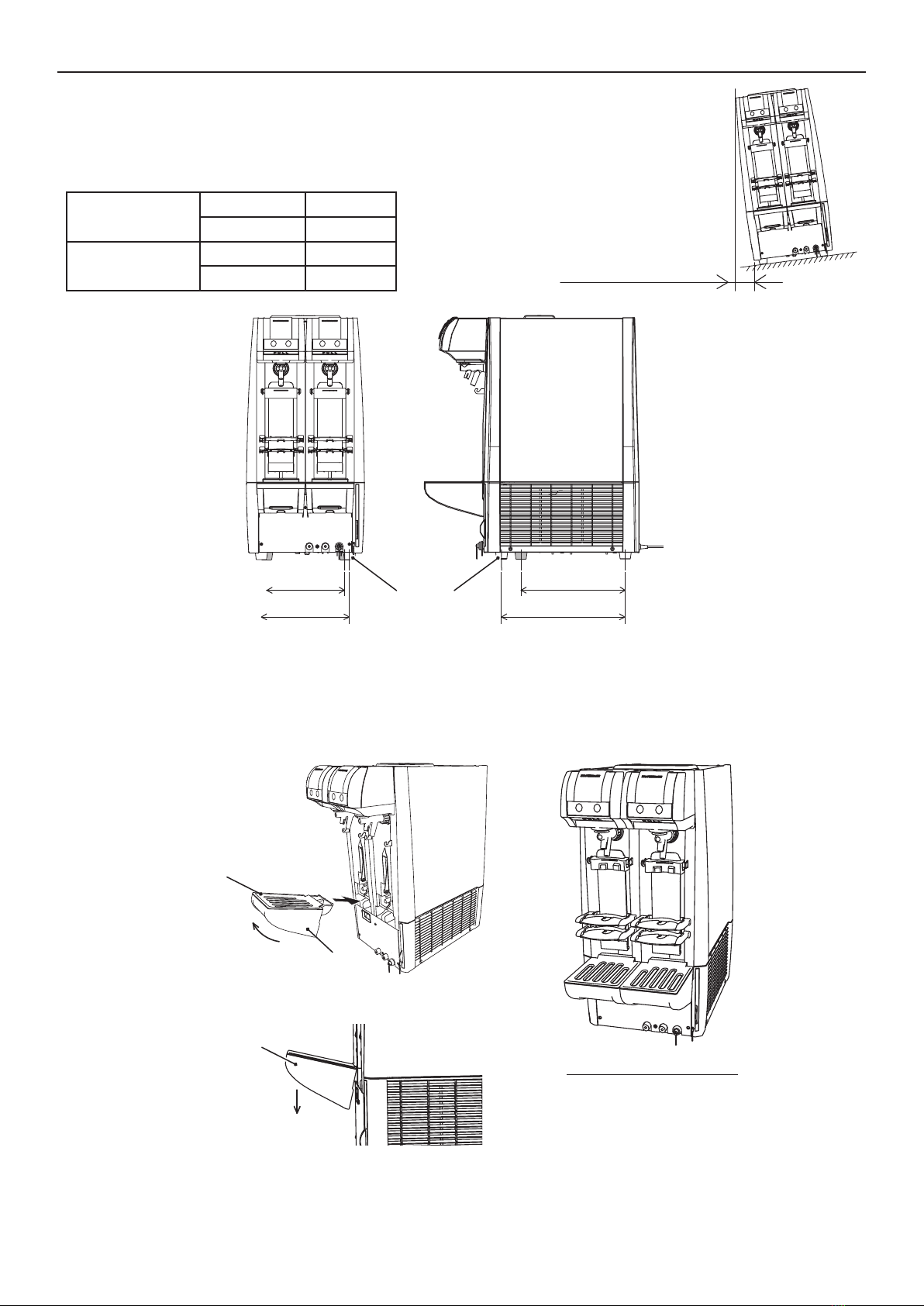
4. LOCATION...........................................................................................................................................................................4
5. INSTALLATION....................................................................................................................................................................4
[a] DISPENSER....................................................................................................................................................................5
[b] DRAIN PAN.....................................................................................................................................................................5
[c] PLATFORM ADJUSTMENT............................................................................................................................................6
6. ELECTRICAL CONNECTIONS ...........................................................................................................................................8
7. GAS AND BEER CIRCUIT CONNECTIONS .......................................................................................................................8
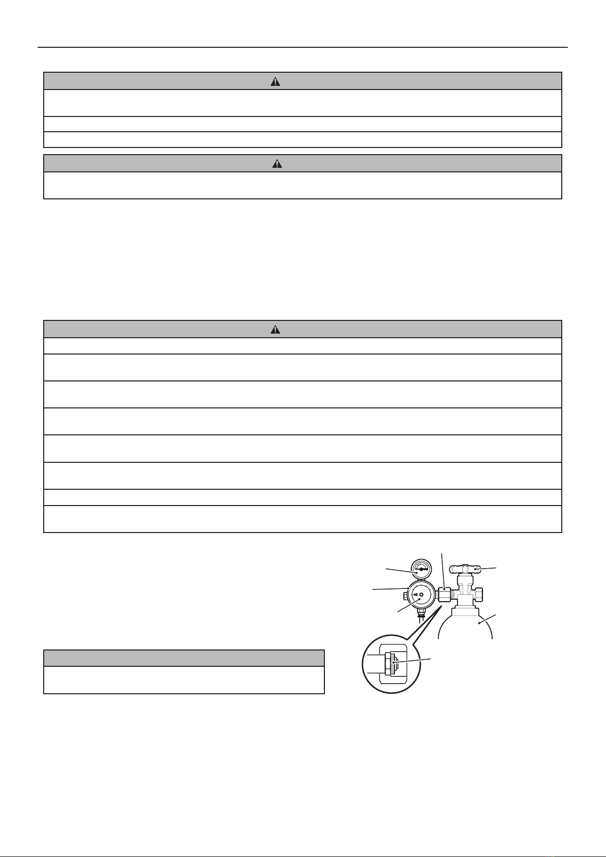
[a] CO2 GAS CYLINDER .....................................................................................................................................................8
[b] HOSE CONNECTIONS...................................................................................................................................................9
[c] CHECKS AFTER CONNECTIONS ...............................................................................................................................10
8. CHECKS AFTER INSTALLATION.....................................................................................................................................10
9. SOLD OUT SENSOR SETTING ........................................................................................................................................11
10. USER SETTINGS ..............................................................................................................................................................11
II. OPERATING INSTRUCTIONS................................................................................................................................................12
1. CLEANING BEER CIRCUIT...............................................................................................................................................12
2. FILLING WATER TANK .....................................................................................................................................................12
[a] HOW TO MAKE COOLING WATER.............................................................................................................................12
[b] COOLING WATER SUPPLY.........................................................................................................................................13
3. CHECKS BEFORE OPERATION (DAILY).........................................................................................................................13
[a] CHECKING CO2 GAS CYLINDER ...............................................................................................................................13
[b] REPLACING CO2 GAS CYLINDER .............................................................................................................................13
[c] CHECKING BEER KEG ................................................................................................................................................14
[d] REPLACING BEER KEG ..............................................................................................................................................14
4. START UP..........................................................................................................................................................................15
[a] SWITCHING MODE......................................................................................................................................................15
[b] LEADING BEER TO TAP..............................................................................................................................................15
5. SETTING LIQUID AND FOAM AMOUNTS........................................................................................................................16
[a] LARGER MUG SETTING..............................................................................................................................................16
[b] SMALLER MUG SETTING............................................................................................................................................16
6. DISPENSING .....................................................................................................................................................................17
[a] AUTOMATIC DISPENSING..........................................................................................................................................17
[b] STOPPING AUTOMATIC DISPENSING ......................................................................................................................17
[c] MANUAL DISPENSING ................................................................................................................................................17
[d] SWITCHING TO AUTOMATIC DISPENSING MODE...................................................................................................18
7. SOLD OUT SENSOR.........................................................................................................................................................18
8. END OF DISPENSING OPERATION ................................................................................................................................18
9. SHUT DOWN .....................................................................................................................................................................19
[a] SHUT DOWN ................................................................................................................................................................19
[b] DRAINING WATER TANK ............................................................................................................................................19
III. MAINTENANCE.......................................................................................................................................................................19
1. BASIC CLEANING .............................................................................................................................................................20
2. BEER CIRCUIT (DAILY) ....................................................................................................................................................20
3. DRAIN PAN AND GRILLE (DAILY)....................................................................................................................................22
4. PLATFORM (DAILY)..........................................................................................................................................................22
5. CLEANING BEER CIRCUIT WITH SPONGE (WEEKLY)..................................................................................................22
6. DISASSEMBLY AND CLEANING OF BEER TAP (WEEKLY)...........................................................................................24
7. KEG COUPLER (WEEKLY)...............................................................................................................................................25
8. EXTERIOR (WEEKLY).......................................................................................................................................................25
9. AIR FILTER (BIWEEKLY) ..................................................................................................................................................25
IV. INSPECTION...........................................................................................................................................................................26
1. COOLING WATER AND ELECTRODE (BIANNUALLY) ...................................................................................................26
2. GAS HOSE AND BEER HOSE (MONTHLY).....................................................................................................................26
3. ATTACHMENT PLUG AND POWER CORD (ANNUALLY / BIANNUALLY) .....................................................................26
V. OTHER INFORMATION ..........................................................................................................................................................27
1. PREPARING THE DISPENSER FOR LONG STORAGE..................................................................................................27
2. BEFORE CALLING FOR SERVICE...................................................................................................................................27
3. RELOCATION, DISPOSAL, TRANSFER...........................................................................................................................28
4. WARRANTY.......................................................................................................................................................................28
SPECIFICATIONS.........................................................................................................................................................................29

1
ENGLISH
IMPORTANT SAFETY INFORMATION
Throughout this manual, notices appear to bring your attention to situations which could result in death, serious injury, or damage
to the unit.
WARNING Indicates a hazardous situation which, if not avoided, could result in death or serious injury.
CAUTION Indicates a hazardous situation which, if not avoided, could result in minor or moderate injury.
NOTICE Indicates a hazardous situation which, if not avoided, could result in damage to the unit.
HYGIENE Indicates important precautions for hygiene and food safety.
IMPORTANT Indicates important information about the use and care of the unit.
IMPORTANT
This booklet is an integral and essential part of the product and should be kept and preserved by the user.
Please read carefully the guidelines and warnings contained herein as they are intended to provide the installer/user with
essential information for the proper installation and the continued safe use and maintenance of the product.
Please preserve this booklet for any further consultation that may be necessary.
WARNING
This is a commercial automatic draft beer dispenser, and should be destined only to be used for the purpose for which it has
been expressly designed.
Any other use should be considered improper and therefore dangerous. The manufacturer will not be held liable or responsible
for any damage caused by improper, incorrect and unreasonable use.
The installation, and relocation if necessary, must be carried out by qualied personnel, in accordance with current
regulations, according to the manufacturer’s instructions.
Keep ventilation openings, in the appliance enclosure or in the built-in structure, clear of obstruction.
The use of any electrical appliance involves the observance of some fundamental rules. In particular:
* Instances of high humidity and moisture increase the risk of electrical short circuits and potential electrical shocks. If in
doubt, disconnect the dispenser.
* Do not damage the power cord or pull it in order to disconnect the dispenser from the electrical supply network.
*Ifthesupplycordand/ortheplugshouldneedtobereplaced,itshouldonlybedonebyaqualiedserviceengineer.
* Do not touch the electrical parts or operate the switches with damp hands.
* This appliance is not intended for use by persons (including children) with reduced physical, sensory or mental capabilities,
or lack of experience and knowledge, unless they have been given supervision or instruction concerning use of the appliance
by a person responsible for their safety.
* Children shall not play with the appliance.
* Cleaning and user maintenance shall not be made by children without supervision.
*Donotattempttomodifythedispenser.Onlyqualiedpersonnelmaydisassembleorrepairtheappliance.

2
ENGLISH
I. INSTALLATION INSTRUCTIONS
1. CONSTRUCTION
NOTICE
Open the panel cover to access the buttons and lamps other than the dispense button (dispense lamp), sold out lamp and
stop button.
To prevent damage to the panel cover, do not open it by force.
Operation Panel
Sold Out Lamp
Lights up when the keg becomes empty.
Flush Lamp
Lights up when the dispenser is
intheushmode.
Flush Button
Switches between the ready
modeandushmode.
Dispense Button (Dispense Lamp)
Lights up when the dispenser is in the ready mode.
[Press once]
Automatically dispenses the preset amount of beer.
[Press and hold]
Makes the automatic dispensing settings available
while in the setting mode.
Stop Button
[Press once]
Manually stops the beer tap or platform
operation.
[Press and hold]
Resets the display indication (e.g.
number of mugs).
Foam Button
[In ready mode]
Press and hold to dispense foam.
[In ush mode]
Press once to dispense foam. Press
again to stop.
Liquid Button
[In ready mode]
Press and hold to dispense liquid.
[In ush mode]
Press once to dispense liquid. Press
again to stop.
Set Lamp
Lights up when the dispenser is
in the setting mode.
Display
Indicates number of mugs and so on.
Set Button
[Press once]
Switches between the setting mode and ready
mode(dispenselampashesrapidly).
[Press and hold]
Used to make user settings (“U_ _” on display).
Operation Panel
Tank Cover
Water Tank
Operation Panel Unit
Platform (Accessory)
Grille (Accessory)
Beer Tap
Air Filter
Drain Outlet
Beer Inlet (Right)Beer Inlet (Left)
Water Level Line (Label)
Drain Pan (Accessory)
Panel Cover

3
ENGLISH
Prepare and install the following equipment. Consult with the liquor shop, beer company or distributor to prepare the regulator,
keg coupler and CO2 gas cylinder designed for the beer to dispense.
[1] CO2 Gas Cylinder
[2] Regulator
[3] Keg Coupler
[4] Quick Beer Hose Joint (Coupler Side)
[5] Quick Beer Hose Joint (Dispenser Side)
[6] Quick Gas Hose Joint (Regulator Side)
[7] Quick Gas Hose Joint (Coupler Side)
[8] Y-Tee
[9] Gas Hose (Short)
[10] Gas Hose (Long)
[11] Beer Hose
[12] Beer Keg
[13] Cleaning Tank
[14] Hook (Accessory)
[15] Cylinder Chain (Accessory)
2. ACCESSORIES
Instruction Manual 1
Instruction Sheet 1
Drain Pan 1
Nozzle Cap 8
Brush 1
Brush (S) 1
Cleaning Sponge 6
Beer Hose Adapter 2
O-Ring (S) P10A 2
Spanner 1
Hook 1
Hook Mounting Screw 2
Cylinder Chain 1
O-Ring (L) P21 1
Grille 1
Platform 2
3. UNPACKING
WARNING
Children should not be allowed in reach of the packaging elements (plastic bags and expanded polystyrene) as they are
potential sources of danger.
CAUTION
Do not lift or manoeuvre the carton by using the shipping bands.
When moving the unit by hand, hold the unit bottom.
Do not hold the beer tap to lift up the unit. The beer tap may be damaged or the unit may fall causing injury.
Always wear protective gloves when carrying the unit.
When handling the carton or the unpacked unit, work in pair to prevent injury.
Instruction Manual Instruction Sheet Drain Pan Nozzle Cap Brush Brush (S)
Cleaning Sponge Beer Hose Adapter O-Ring (S) P10A Spanner Hook
Hook Mounting Screw Cylinder Chain O-Ring (L) P21 Grille Platform

4
ENGLISH
NOTICE
Remove shipping carton, tape(s) and packing. If packing material is left in the dispenser, it will not work properly.
To prevent damage, do not tilt the dispenser more than 45°.
1) After removing the packaging, make sure that the dispenser is in good condition. If in doubt, please do not use the dispenser
butapplytoprofessionallyqualiedpersonnel.
2)Removetheprotectiveplasticlmfromtheexterior.Ifthedispenserisexposedtothesunortoheat,removethelmafterthe
dispenser cools.
3) Remove the package of accessories. Check the contents according to “2. ACCESSORIES”.
4. LOCATION
WARNING
This dispenser is not intended for outdoor use.
The dispenser should not be located next to ovens, grills or other high heat producing equipment.
This appliance is not suitable for installation in an area where a water jet could be used.
CAUTION
Thelocationshouldprovidearmandlevelfoundationforthedispenser.
NOTICE
Do not place anything to obstruct the ventilation louvers.
IMPORTANT
Normal operating ambient temperature should be within 5°C to 32°C, cooling water temperature not more than 25°C, and beer
keg temperature within 10°C to 30°C. Operation of the dispenser, for extended periods, outside of these normal temperature
rangesmayaectproductioncapacity.
Allow 10 mm extra space at the installation site to meet any installation requirements (additional spacing is also required for
properairowandpipeconnections).
Keep the dispenser away from direct sunlight.
Allowtheclearancespeciedbelowforproperaircirculationand
ease of maintenance and/or service should they be required.
Insomehighhumidityenvironments,condensationmayforminsidethemachineanddripontotheoor.Donotinstallwhere
theoorcanbeaectedbywater.
5. INSTALLATION
CAUTION
Incorrect installation can cause harm to people, animals or other items, for which the manufacturer cannot be held
responsible.
Min 50 mm
Min 510 mm
Air Air
Air
Front Min 100 mm
Min 50 mm

5
ENGLISH
[a] DISPENSER
The front rubber feet can be moved backward from their original position. If the feet
cannottwithintheinstallationspaceonthecounterortable,useascrewdriverto
removethefrontfeetfromthebottomandretatthefollowingpositions.
Factory Setting Distance: A 274 mm
Distance: B 388 mm
After Adjustment Distance: a 244 mm
Distance: b 328 mm
[b] DRAIN PAN
To attach the drain pan (accessory) and grille (accessory):
(1) lift up the front of the drain pan,
(2) push the drain pan securely into the drain pan support, and
(3) push down the front of the drain pan.
Do not tilt more than 1 cm
Distance: b
Distance: B
Rubber Foot
Distance: a
Distance: A
After installation of accessories
(2) Push in
(1) Lift up front
Grille
Drain Pan
Drain Pan
(3) Push down front

6
ENGLISH
[c] PLATFORM ADJUSTMENT
Theupperandlowerplatformpositionsareadjustabletoaccommodatetwodierentmugheights.Theguidecanalsobemoved
back and forth according to the mug shape.
1) The platform assembly has the components as
shown on the right.
2) Move the platform in the desired position and secure it with the screws.
The upper platform position is adjustable between the 1st and 7th levels of the mug
plate, and the lower platform position between the 4th and 12th levels. The top of
themugmusttthemarkonthebackplatewhenpositionedontheplatform.(See
the table on the next page for the mug heights and platform positions.)
3)Afteradjustingtheplatformpositions,ttheguidetopositionthebottomofthe
mug. The guide with cover is for the upper platform.
4)Rettheplatformstotheunit.
NOTICE
When adjusting the upper platform position, also adjust the bracket position according to the table on the next page.
Mug Plate
Upper Platform
Built-in
Sensor
Magnet
Lower Platform
Mark
Back
Plate
Screw
Front Rear
Remove screws
on both sides
Shift
Guide
Cover
Hook
(2)Ret
(1) Adjust position
(3) Secure with screws
on both sides

7
ENGLISH
Mug Plate Level Upper Platform Lower Platform
Mounting Hole Mug Height (mm) Bracket Position Mounting Hole Mug Height (mm)
1Lower 135
ANot available
Upper 140
2Lower 145
Upper 150
3Lower 155
Upper 160
4Lower 165 Lower 155
Upper 170
B
Upper 160
5Lower 175 Lower 165
Upper 180 Upper 170
6Lower 185 Lower 175
Upper 190 Upper 180
7Lower 195 Lower 185
Upper 200 Upper 190
8
Not available
Lower 195
Upper 200
9Lower 205
Upper 210
10 Lower 215
Upper 220
11 Lower 225
Upper 230
12 Lower 235
Upper 240
Note:
1) Mug diameter: 50 mm inside diameter to 105 mm outside diameter and bottom diameter
2) The larger mug must be at least 20 mm higher than the smaller mug.
Bracket
Position: A (Factory Setting)
Position: B
Bracket PositionPlatform Position
1st Level
12th Level
Upper
Mounting
Hole
Lower
Mounting
Hole
Min 20 mm
Fit on boss

8
ENGLISH
6. ELECTRICAL CONNECTIONS
WARNING
THIS APPLIANCE MUST BE EARTHED
This dispenser requires an earth that meets the national and local electrical code requirements.
To prevent possible severe electrical shock to individuals or extensive damage to the unit, install a proper earth wire to the dispenser.
Remove the plug from the mains socket before any maintenance, repairs or cleaning is undertaken.
CAUTION
The maximum allowable voltage variation should not exceed ±10 percent of the rated voltage. Operation of the unit outside of
this range may cause smoking, ignition, damage to the unit or reduction of the performance.
* This appliance requires a separate power supply. The electrical supply must be protected by a suitable circuit breaker.
* Usually an electrical permit and services of a licensed electrician are required.
* If the supply cord is damaged, it must be replaced by a replacement cord available from your dealer/supplier.
7. GAS AND BEER CIRCUIT CONNECTIONS
[a] CO2 GAS CYLINDER
WARNING
Use a CO2 gas cylinder designed for use with beer. Use of any other cylinders may cause explosion or air pollution.
While carrying the CO2 gas cylinder, keep the cap closed and avoid any impact on the cylinder to prevent the risk of explosion
or gas leaks.
Keep the CO2 gas cylinder away from direct sunlight or temperatures above 40°C to avoid excessive temperature rise and
explosion.
The regulator must be provided with an undamaged gasket to prevent the risk of gas leaks. If not, contact the liquor shop,
beer company or distributor to install a new gasket.
Stand the CO2 gas cylinder upright, and x it securely with the accessory chain to prevent overturn resulting in injury or
explosion.
KeepyourfaceawayfromtheCO2gascylinderwhileblowingdirtanddustotheregulatorjoint.Dustgettinginyoureyes
can cause visual impairment.
Handle the regulator with care to avoid any impact, or it may not work properly and the beer keg or hose can explode.
Before opening the main valve of the CO2 gas cylinder or removing the keg coupler from the beer keg, set the regulator to “0”.
Otherwise,suddenapplicationofgaspressureonthebeerkegmaycauseexplosionorblow-oofthekegcoupler.
1) Open the main valve of the new CO2 gas cylinder for a second to
blowdirtanddustothejoint(togetherwithCO2gas).
2) Check the regulator gasket. If it is damaged or not provided,
install a new gasket. (Contact the liquor shop, beer company or
distributor.)
3) Install the regulator securely on the CO2 gas cylinder.
NOTICE
Tightenthenutbyhandrst,thenwiththespanner(accessory)so
that the level gauge will be upright.
4) Open the main valve by turning it counterclockwise, and check the regulator nut for gas leak (sound). If gas is leaking, the nut
must be loose or the gasket must be damaged or not provided.
Note: To check for gas leaks, apply a sponge with soap to the joint. Bubbles form if gas is leaking.
Level Gauge
Nut
Main Valve
Regulator
Adjust Dial
Gasket
CO2 Gas Cylinder
*Theregulatordesignisdierent
for each beer company.

9
ENGLISH
[b] HOSE CONNECTIONS
WARNING
Topreventtheriskofgasleaksandhoseexplosion,donotuseanyhosesotherthanspeciedbythebeercompany.
Cut the hose end to have a vertical cutting plane and insert it securely into the quick hose joint to ensure a leak-free joint.
NOTICE
Do not reconnect the hoses without cutting them about 20 mm.
Cut the hoses with a specialized tool such as hose cutter. Do not use scissors, or the hoses may be crushed to cause leaks.
CO2 Gas Hose
1) Cut the CO2 gas hose to have a vertical cutting plane and a hose length not
more than 1.4 m.
2) Insert the CO2 gas hose securely into the quick gas hose joint on the keg
coupler and regulator. Pull the hose hard to check for tightness.
Quick Gas Hose Joint
1) To connect the CO2 gas hose, push it all
the way in.
2) To disconnect the CO2 gas hose, push
andholdpart(1)withngersandpullout
the hose (2).
Beer Hose
1) Attach the O-ring (S) P10A (accessory) to the smaller end of the beer hose
adapter (accessory), and connect that same end to the beer inlet (two
places).
2)Attachthequickbeerhosejointspecied
by the beer company to the beer hose
adapter.
3) Cut the beer hose to have a vertical
cutting plane and a hose length not more
than 2.1 m.
4) Insert the beer hose securely into the keg coupler and quick beer hose joint. Pull the
hose hard to check for tightness.
Note: It depends on the beer company how to connect and disconnect the beer hose
to and from the quick beer hose joint.
Quick Gas Hose Joint Gas Hose
Push
(1) (2)
O-Ring (S)
Beer Hose Adapter
(smaller end)
Beer Inlet
Beer Hose Adapter
Quick Beer Hose Joint
Keg Coupler
Rotary Type Vertical Type
Beer Hose
Keg Coupler Regulator
Rotary Type Vertical Type

10
ENGLISH
[c] CHECKS AFTER CONNECTIONS
1)Washthecleaningtankthoroughlyandllitwithtapwater.
Note: If the cleaning tank is not clean, the beer circuit will be contaminated.
2) Turn the keg coupler clockwise to attach it to the cleaning tank.
Note: Wash the joint between the keg coupler and cleaning tank if it is not clean.
3) Lift up and remove the platform.
4) Place a bucket on the drain pan to receive cleaning water.
5) Check that the beer tap lever is in the closed (normal) position. Open the main
valve of the CO2 gas cylinder by turning it counterclockwise a few times.
6) Turn the regulator adjust dial to set the pressure to “0.15” (MPa).
7) Open the beer circuit.
Rotary type: Turn the keg coupler handle clockwise until it stops.
Vertical type: Push down the keg coupler handle until it locks in place.
Note: If the cleaning tank is provided with a siphon tube, lay the cleaning tank with the ferrule at the top. If not, lay the
cleaning tank with the ferrule at the bottom.
8) Pull the beer tap lever toward you to pour water out of the liquid nozzle.
9) Check the CO2 gas circuit for gas leaks. If it is leaking, correct the hose connections.
10) Check the beer circuit for water leaks. If it is leaking, correct the hose connections.
11) Keep the beer tap lever in the open position and
turn the regulator adjust dial to set the pressure to “0”
(MPa).
12) Close the main valve of the CO2 gas cylinder by
turning it clockwise.
13) When CO2 gas stops coming out of the nozzle,
push the beer tap lever back to the closed position.
8. CHECKS AFTER INSTALLATION
1)Fillthewatertankwiththespeciedwater.See“II.2.FILLINGWATERTANK”.
2) Flush the beer circuit and check for water leaks. See “III. 2. BEER CIRCUIT”.
3) Check for proper power supply voltage.
4) Plug in the unit.
* Check that the refrigeration unit and agitator motor start.
(In low temperature conditions, the condenser fan motor may not start until the condenser temperature goes up.)
Keg Coupler Handle
Rotary Type Vertical Type
Siphon Tube
Provided Not provided
Bucket
Open Position
CO2 Gas Cylinder
Close
Lever
Closed Position
Lever
Closed Position CO2 Gas Cylinder
Open
Rotary Type Vertical Type

11
ENGLISH
* After 8 to 13 hours (depending on ambient/water temperature), open the top cover and check that ice is stored in the water
tank.
5) Instruct the user on how to operate the unit.
6) Hand this instruction manual to the user.
9. SOLD OUT SENSOR SETTING (“U07”)
Choose among the four modes according to the type of beverage to dispense (e.g. beer, cocktail).
1) Lower the operation panel unit on the desired side.
2) Press and hold the set button on the operation panel to show “U01” on the display.
3) Use the foam button or liquid button to show “U07” on the display.
4) Press the set button to show the current number on the display. Use the foam button or liquid button to choose the desired
number(seetablebelow).Pressthesetbuttontosettheashingnumber.
No. Setting
0 Setting A (mainly beer)
1 Setting B (mainly cocktail)
2 Setting C (mainly cocktail)
3 Setting D (optional)
Note: The sold out sensor is factory set to “0: Setting A (mainly beer)”. The setting depends on the brand of beverage to
dispense. Check with your dealer/supplier.
5) Press the set button again to show “U07” on the display. Press and hold the set button for more than 3 seconds to complete
the setting.
Note: If no operation is performed for more than 1 minute, the dispensing mode is resumed. In that case, go back to step 2)
above.
10. USER SETTINGS
To make or change settings:
Press and hold the set button for 3 seconds to enter the setting mode (see “9. SOLD OUT SENSOR SETTING”).
To complete settings:
With “U_ _” on the display, press and hold the set button for 3 seconds to enter the dispensing mode.
The dispensing mode is also resumed if no operation is performed for more than 1 minute.
Item Description Default Setting Range
U01 Digital display
(in dispensing mode)
0: No indication
1: Number of mugs (*)
* Number switches between the larger and smaller mugs when the mug
setting is changed.
* To reset, press and hold the stop button for 3 seconds.
0 0 - 1
U02 Log of number of mugs
Log of number of mugs for each reset in descending order
* Log is indicated in turn for each keg replacement by “U04”.
* Log is indicated for both larger and smaller mugs when the mug setting is
changed.
* To reset all the current and past logs, press and hold the stop button for 3
seconds. This reset is not counted for “U04”.
0 Up to 5 logs
U03 Numberofushcycles
Numberofushcyclesperformed
*A ushcycleconsistsof liquid button operation(total10seconds) + foam
button operation (total 3 seconds) in the flush mode except when no
automatic dispensing action is made during the cycle.
* To reset, press and hold the stop button for 3 seconds.
0 0 - 9999

12
ENGLISH
U04
Number of keg
replacements
(reset frequency)
Reset frequency for number of mugs
* Keg replacement is counted every time the number of kegs is reset by the
stop button operation.
* To reset, press and hold the stop button for 3 seconds.
0 0 - 9999
U05 Dispense lamp
brightness Adjustment of dispense lamp brightness 6 1 - 8
U06 Dispenselampashing
duration
Adjustment of dispense lamp ashing duration after completion of
dispensing
*Thedispenselampashestopreventanothermugisplacedwhilefoamis
still dripping.
*Automaticdispensingactionisnotavailablewhilethelampisashing.
1 0 - 10
U07 Sold out sensor setting
0: Setting A (mainly beer) / threshold: 2.2V
1: Setting B (mainly cocktail) / threshold: 2.5V
2: Setting C (mainly cocktail) / threshold: 2.8V
3: Setting D (optional) / threshold: optional
* The setting depends on the brand of beverage to dispense. Check with your
dealer/supplier.
0 0 - 3
U08 Self mode setting
0: No
1: Yes (no button operation is available except dispense/stop button)
* The self mode is reset when the manual dispensing mode is selected (by
lifting up the operation panel unit). To resume the self mode, switch to the
automatic dispensing mode (by pulling down the operation panel unit) and
press the dispense button.
0 0 - 1
U09 Mug tilting operation 0: Yes (mug is tilted while beer is being dispensed)
1: No (mug is kept upright while beer is being dispensed) 0 0 - 1
U10 Reset number of mugs
0: Manual
1: Manual or when sold out sensor detects
* To reset manually, press and hold the stop button for 3 seconds.
0 0 - 1
U90 Reset settings
Initialize only the user settings
* To initialize, with “1” shown on the display, press and hold the stop button
for 3 seconds.
* If the settings are updated, “U90” appears on the display. If not updated, “0”
appears again.
0 0 - 1
II. OPERATING INSTRUCTIONS
1. CLEANING BEER CIRCUIT
Although the beer circuit is cleaned before shipping, clean it again before use. See “III. 2. BEER CIRCUIT”.
Check that the parts are installed in their correct positions. See “I. 1. CONSTRUCTION”.
2. FILLING WATER TANK
NOTICE
Useonlythespeciedwatertollthewatertank.Useofanyotherwaterormixtureofsalt,vinegarorjuicemaycauseinsucient
ice storage, corrosion or perforation.
[a] HOW TO MAKE COOLING WATER
IMPORTANT
Carefullyreadthisbeforellingthewatertank.
Electric conductivity (E.C.) of cooling water for water tank
Do not use tap water.
Fillthewatertankwithwaterhaving100-300μS/cmofE.C.
Measure the electric conductivity with conductivity meter.
* E.C. : Physical property to show the ability of conducting electricity.
Unit:μS(microsiemens)/cm
Below100μS/cm:
Compressor may not work resulting in poor cooling performance.

13
ENGLISH
Above300μS/cm:
Excessive ice may build up on evaporator and freeze beer inside beer coil preventing beer from being dispensed properly.
How to make cooling water with 100-300 μS/cm of E.C.
The capacity of the water tank of this unit is approx. 30 L.
Make the cooling water by dissolving 5 g of pure baking soda in approx. 10 L of distilled water,
andthenaddapprox.27Lofdistilledwatertollthewatertank.
Step 1
Measure 5 g of pure baking soda with nozzle cap (accessory).
Step 2
Fill a bucket with approx. 10 L of distilled water and stir well after adding the 5 g of baking
soda measured in step 1.
Rinse the nozzle cap after use.
[b] COOLING WATER SUPPLY
WARNING
Beforellingthewatertank,turnothepowerswitch(earthleakagebreaker)andunplugtheunit.
NOTICE
Do not splash water on the electrical parts.
Donotllthewatertankabovethewaterlevelline,orthedrainpanwilloverowandspillwater.
1) Remove the top cover.
2) Pour the bucket (approx. 10 L) of cooling water prepared.
3) Fill the water tank up with approx. 27 L of distilled water to the water level line marked inside
the water tank.
4) Use a conductivity meter if measuring the electric conductivity.
5) Close the top cover.
3. CHECKS BEFORE OPERATION (DAILY)
[a] CHECKING CO2 GAS CYLINDER
Open the main valve of the CO2 gas cylinder, and check the gas
pressure by the level gauge of the regulator:
* If the level gauge reading is not more than 3 MPa or falls into the
yellow zone, the cylinder contains little CO2 gas.
* If the level gauge reading is not more than 1 MPa or falls into the
red zone, replace with a new cylinder.
[b] REPLACING CO2 GAS CYLINDER
1) Close the main valve of the CO2 gas cylinder by turning it clockwise.
2) Turn the regulator adjust dial to set the pressure to “0” (MPa).
3) Use the spanner (accessory) to loosen the nut and remove the regulator from the CO2 gas
cylinder.
Note: Be sure to cap the CO2 gas cylinder.
4)OpenthemainvalveofthenewCO2gascylinderforasecondtoblowdirtanddustothe
joint (together with CO2 gas).
Level Gauge
Nut
Main Valve
Regulator
Adjust Dial
Gasket
CO2 Gas Cylinder
*Theregulatordesignisdierent
for each beer company.
Cap
Distilled Water
(approx. 10 L)
Bucket
Nozzle Cap 5/6
(5 g)
Nozzle Cap
Water Tank
中文:478537L01

14
ENGLISH
5) Check the regulator gasket. If it is damaged or not provided, install a new gasket. (Contact the liquor shop, beer company or
distributor.)
6) Install the regulator securely on the CO2 gas cylinder.
NOTICE
Tightenthenutbyhandrst,thenwiththespanner(accessory)sothatthelevelgaugewillbeupright.
7) Open the main valve by turning it counterclockwise, and check the regulator nut for gas leak (sound). If gas is leaking, the nut
must be loose or the gasket must be damaged or not provided.
Note: To check for gas leaks, apply a sponge with soap to the joint. Bubbles form if gas is leaking.
8) Turn the regulator adjust dial to set to an appropriate pressure as shown below.
WARNING
The CO2 gas pressure on the beer keg must not exceed 0.37 MPa. Otherwise, the beer keg or hose can explode resulting in
injury.
The CO2 gas pressure on the beer keg prevents separation of CO2 gas from beer. The higher the beer keg temperature is, the
easier the CO2 gas separates and a higher gas pressure is required.
Beer Keg Temperature Gas Pressure
Note: The values are for reference only. Set to the appropriate
pressurespeciedbythebeercompany.
10°C 0.20 MPa (Scale 2)
20°C 0.22 MPa (Scale 2.2)
30°C 0.32 MPa (Scale 3.2)
[c] CHECKING BEER KEG
If the sold out lamp comes on and no more beer is dispensed, replace the beer keg.
Do not store an open beer keg in a refrigerator. But keep it under 30°C.
[d] REPLACING BEER KEG
WARNING
Donotloosentheferruleonthebeerkeg,orinsidepressuremayblowotheferruleresultingininjury.
Handle the beer keg with care to avoid vibration. Rolling or shaking the beer keg can cause excessive foaming.
1) Close the beer circuit.
Rotary type: Turn the keg coupler handle counterclockwise until it stops.
Vertical type: Unlock and lift the keg coupler handle all the way up.
Keg Coupler Handle
Rotary Type
Keg Coupler
Beer Keg
Vertical Type
Keg Coupler Handle
Keg Coupler
Beer Keg
Keg Coupler Handle
Rotary Type Vertical Type

15
ENGLISH
2) Turn the regulator adjust dial to set the pressure to “0” (MPa).
3) Turn the keg coupler counterclockwise to
remove it from the beer keg.
4) Turn the keg coupler clockwise to attach it to the new beer keg.
Note: Wash the joint between the keg coupler and beer keg if it is not clean.
5) Turn the regulator adjust dial to set to an appropriate pressure according to the beer
keg temperature. See “[b] REPLACING CO2 GAS CYLINDER”.
6) Open the beer circuit.
Rotary type: Turn the keg coupler handle clockwise until it stops.
Vertical type: Push down the keg coupler handle until it locks in place.
7) Before dispensing beer, lead beer to the beer tap according to “4. [b] LEADING BEER
TO TAP”.
4. START UP
WARNING
Incaseofagasleak,turnothemaingassupplyandventilatetheroom.Topreventsparksandresultingreandexplosion,
do not unplug the unit.
Donotusecombustiblesprayorplacevolatileandammablesubstancesneartheunit.Theycouldcatchrefromsparks.
Ifthepowergoeso,contactyourdealer/supplier.Topreventelectricshockorre,donotturnitbackon.
In case of trouble, unplug the unit or disconnect the main power supply, and immediately contact your dealer/supplier. To
preventpossibleelectricshockorre,donotkeeptheunitinoperation.
1) Plug in the unit.
2) The refrigeration unit and agitator motor start.
IMPORTANT
It takes about 8 to 13 hours from startup to completion of ice storage in the water tank. Dispensed beer may not be cold
enough until ice production completes.
[a] SWITCHING MODE
Eachpushoftheushbuttonontheoperationpanelwillswitchbetweenthereadymodeandushmode.Inthereadymode,
thedispenselamplightsup.Intheushmode,theushlamplightsup.
[b] LEADING BEER TO TAP
1)Checkthattheregulatoradjustdialissettotheappropriatepressurespeciedbythe
beer company.
2) Open the beer circuit.
Rotary type: Turn the keg coupler handle clockwise until it stops.
Vertical type: Push down the keg coupler handle until it locks in place.
3) Place a mug on the platform.
Keg Coupler Handle
Rotary Type Vertical Type
Keg Coupler Handle
Rotary Type Vertical Type

16
ENGLISH
4) Press and hold the foam button to purge air out of the beer circuit through the foam nozzle. Release the foam button when no
moreairispurgedandasteadyowoffoamisobtained.Whenbeerreachesthesoldoutsensor,thesoldoutlampgoeso
and the ready lamp comes on.
5) Press the liquid button to check that clear beer is dispensed. Release the liquid button to stop beer.
IMPORTANT
If the liquid nozzle is used to purge air out of the beer circuit, liquid will splash out together with gas. When connecting or
replacing a beer keg, always use the foam nozzle to purge air.
5. SETTING LIQUID AND FOAM AMOUNTS
CAUTION
Toreducetheriskofinjury,donotputyourngersbehindtheplatformwhileitismoving.
IMPORTANT
The liquid and foam amounts are adjusted by visual check of dispensed beer and button operation. The set amounts vary with
the CO2 gas pressure. Readjustment is necessary every time the CO2 gas pressure is changed.
The setting is available for any two mug sizes. Place the larger mug on the lower platform and the smaller mug on the upper
platform. The larger mug must be at least 2 cm higher than the smaller mug.
The automatic dispensing is intended for a standard glass mug. To avoid excessive foaming, do not use a paper cup or
ceramic mug.
The set amounts may vary depending on the ambient temperature, beer keg temperature, use condition and remaining beer
level.
The tolerance of set amounts is about 30 mL per 400 mL mug. The CO2 gas pressure must be adjusted according to the beer
keg temperature. The set amounts may vary depending on the performance of the regulator controlling the CO2 gas pressure.
If the set amounts vary too much, the regulator must be replaced.
Emptythedrainpanfrequentlybeforeitoverowsontotheoor.Thecoolingwaterinsidethewatertankabsorbsmoisturein
theairandowsthroughtheoverowhoseintothedrainpan.
[a] LARGER MUG SETTING
1) Flip up the upper platform (accessory). Place a clean mug on the lower
platform (accessory) with its back against the wall.
2)Pressthesetbutton.Thesetlamplightsupandthedispenselampashes.
3) Press and hold the dispense button to raise the platform up to an angle of
40 degrees.
4) While pressing the dispense button, press and hold the liquid button. When the desired amount of liquid is dispensed, release
the liquid button only. The platform stays at an angle.
5) While pressing the dispense button, choose how to move the platform back to the original position.
To move the platform while dispensing liquid, press and hold the liquid button for the desired dispensing duration.
To move the platform without dispensing liquid, press the stop button.
6) [If no foam is needed, skip step 6) and go to step 7).]
While pressing the dispense button, press and hold the foam button. When the desired amount of foam is dispensed, release
the foam button only. To add more foam, press the foam button again.
7)Releasethedispense buttonto completethe largermugsetting.Thesetlampgoeso and
thedispenselampstopsashingandstayson.Ifthesettingfailstocomplete,gobacktostep2).
[b] SMALLER MUG SETTING
1) Flip down the upper platform. Place a clean mug on the upper platform with its back against
the wall.
2) See steps 2) to 7) in “[a] LARGER MUG SETTING”.
Upper Platform
Lower Platform
Upper Platform

17
ENGLISH
6. DISPENSING
[a] AUTOMATIC DISPENSING
1) Check that the beer tap is not dripping. Place a clean mug on the same platform as used for the setting.
2) Press the dispense button. The unit automatically dispenses the set amount of liquid and
foam.
IMPORTANT
The mug tilting operation is factory set to “0: Yes” (mug is tilted while beer is being
dispensed).
3) To add more foam, press and hold the foam button until the desired amount of foam is dispensed.
IMPORTANT
Place a mug on the platform after the beer tap stops dripping remaining foam.
[b] STOPPING AUTOMATIC DISPENSING
IMPORTANT
If power failure occurs during the dispensing operation and the operation panel unit is lifted up, do not pull it down by force
after power supply is resumed, but contact your dealer/supplier.
Ifthedisplayshowsanerrorcode(E__),turnothepowersupplyandturnitbackon.Ifthedisplaystillshowstheerrorcode,
contact your dealer/supplier.
To stop the automatic dispensing operation halfway through:
1) Press the stop button. The platform stops at that position.
When the stop button is pressed again, the platform goes back to the original position.
2) If the dispensing operation does not stop with the stop button pressed, lift up the operation panel unit. The
beer tap lever comes o the operation panel unit and goes back to the closed position. If beer still keeps
running, move the lever back and forth.
CAUTION
To reduce the risk of injury, donotputyourngersintothebottomopeningoftheoperationpanelunitwhileit
is lifted up.
3) Close the keg coupler attached to the beer keg. See “II. 3. [d] REPLACING BEER KEG”.
To stop the automatic dispensing operation in case of power failure or error:
Follow steps 2) and 3) above.
[c] MANUAL DISPENSING
1) Lift up the operation panel unit slowly until it locks into place. The display shows “OFF”.
2) To dispense beer, pull the beer tap lever quickly toward you until it stops. To avoid
excessive foaming, do not pull the lever slowly or stop it halfway. Release the lever to
stop beer.

18
ENGLISH
3) To dispense foam, push the beer tap lever quickly away from you until it
stops. To avoid liquid foam, do not stop the lever halfway. Release the lever
to stop foam.
Note: When the beer tap lever is pushed during manual dispensing operation,
the valve shaft end comes out. Be careful not to hit the mug on the
shaft.
[d] SWITCHING TO AUTOMATIC DISPENSING MODE
1) Hold the bottom of the operation panel unit and pull the front handle toward you to unlock.
2) Pull down the operation panel unit until it stops to cover up the beer tap lever. The dispense
lamp comes on.
CAUTION
To prevent injury, do not hold the cross-marked part but hold the curved surface at the front
side when pulling down the operation panel unit.
To avoid damage, do not pull down the operation panel unit by force without unlocking the
handle.
7. SOLD OUT SENSOR
When the beer keg becomes empty, the unit automatically detects the condition and stops
the dispensing operation. The sold out lamp lights up, and the dispense button becomes
unavailable.
IMPORTANT
The sold out sensor is factory set to “0: Setting A (mainly beer)”.
In the manual dispensing mode, the unit will not stop dispensing even if the sold out lamp lights up. Be careful with the keg
level while dispensing beer.
When the sold out lamp lights up, replace the beer keg. See “3. [d] REPLACING BEER KEG” and “4. [b] LEADING BEER TO
TAP”.
8. END OF DISPENSING OPERATION
1) Close the beer circuit.
Rotary type: Turn the keg coupler handle counterclockwise until it stops.
Vertical type: Unlock and lift the keg coupler handle all the way up.
IMPORTANT
When the keg coupler on the keg is closed, gas may stay inside the beer circuit. To
prevent excessive foaming or improper dispensing actions, lead beer into the beer
circuit until gas comes out of the beer tap before starting operation on the following
day. See “4. [b] LEADING BEER TO TAP”.
2) Flush the beer circuit according to “III. 2. BEER CIRCUIT”.
3) Turn the regulator adjust dial to set the pressure to “0” (MPa).
4) Close the main valve of the CO2 gas cylinder by turning it clockwise.
Note: To prevent too much CO2 gas entering the beer keg, always close the main valve of the CO2 gas cylinder at the end of
dispensing operation.
Mug
Valve Shaft End
Hold here
Handle
Operation Panel Unit
Lever
Beer Tap
Keg Coupler Handle
Rotary Type Vertical Type
Table of contents
Other Hoshizaki Kitchen Appliance manuals