Hoshizaki DBF-25SB-AU User manual

DRAFT BEER DISPENSER DBF-25SB-AU
DBF-43SB-AU
INSTRUCTION MANUAL
L168QU111 (062012)

1
IMPORTANT
1. This bookletis anintegral andessential partof theproduct
andshouldbekeptandpreservedbytheuser.Pleaseread
carefully the guidelines and warnings contained herein as
theyareintendedtoprovidetheinstaller/userwithessential
informationfortheproperinstallationandthecontinuedsafe
use and maintenance of the product. Please preserve this
bookletforanyfurtherconsultationthatmaybenecessary.
2. This is adraft beer dispenser, and shouldbe destined only
to be used for the purpose for which it has been expressly
designed.Anyotheruseshouldbeconsideredimproperand
thereforedangerous.Themanufacturerwillnotbeheldliable
orresponsibleforanydamagecausedbyimproper,incorrect
andunreasonableuse.
I. INSTALLATION
WARNING
The installation must be carried out by qualied personnel,
inaccordancewithcurrentregulations,accordingtothe
manufacturer’sinstructions.
1. CONSTRUCTION
[a] DISPENSER
[1]Agitatormotor
Agitatescoolingwaterinthewatertankforeffectivecoolingofbeer.
[2]Innercover
[3]Unionnut
[4]Beertap
Poursbeerintoamug.
[5]Nameplate
[6]Drainboard(accessory)
[7]Drainpan(accessory)
[8]Beerinlet
[9]Drainoutlet
Drainscoolingwaterfromthewatertank.Closedwitharubberplug.
[10]Overowhose
Maintainsaconstantlevelofcoolingwaterinthewatertank.
[11]Watertank
Formsiceforbeercoolingwater.
[12]Machinecompartment
Containsrefrigerationcircuitandelectricalcomponents.
[13]Topcover
[b] ACCESSORIES
Instructionmanual 1pc
Brush 1pc
Cleaningsponge 6pcs
Brush(S) 1pc
Spanner 1pc
Hook 1pc
Hookmountingscrew 2pcs
Chain 1pc
Beerhoseadaptor 1pc
Drainpan 1pc
Drainboard 1pc
Nozzlecap 3pcs
O-ringP10A 1pc
O-ringP21 1pc
2. UNPACKING AND LOCATION
CAUTION
1. To prevent injury, wear work gloves and hold the bottom
paneltocarrytheunit.Workinapairorgroup.
2.Thelocation shouldprovideafirmandlevelfoundation
for the equipment to avoid the risk of water leaks or injury
causedbyoverturnorfall.
3. To prevent possible damage or injury, do not hold the beer
taptocarrytheunit.
4. This unit is not intended for outdoor use. Exposure to rain
maycauseelectricleakageorshock.
1)Inspect the packagefordamage.Anyextensivedamagefound
shouldbereportedtothecarrier.
2)Afterremovingthepackaging,removetheprotectiveplasticlm.
3)Checktheexteriorandinteriorpartsfordamage.
4)Checkthatalltheaccessorieslistedin“1.[b]ACCESSORIES”are
includedandnotdamaged.
IMPORTANT
1. Normaloperatingambienttemperatureshouldbewithin5°C
to35°C.
2. Avoida sitewhere drippingis notallowed. In high humidity
conditions, condensation on the exterior may drip onto the
installationsurfacesoroor.
3. Theunitshouldnotbelocatednexttoovens,grillsorother
highheatproducingequipment.
4.Allow5cmclearanceatrearandsidesforproperair
circulation. Otherwise the cooling performance may reduce
andelectricitycostswillincrease.
5. Donotremovethelabels.
3. ELECTRICAL CONNECTIONS
WARNING
THIS APPLIANCE MUST BE EARTHED
This unit requires an earth that meets the national and local
electricalcoderequirements.Topreventpossiblesevere
electricalshocktoindividualsorextensivedamageto
equipment,install aproper earth wire to theunit. Removethe
plugfromthemainssocketbeforeanymaintenance,repairsor
cleaningisundertaken.
[1]
[2]
[3]
[4]
[5]
[6]
[7]
[8] [9]
[10]
[11]
[12]
[13]

2
* Themaincontrolboxfuseisratedat10Aandshouldonlybe
replacedbyaqualiedserviceengineer.
* Usually an electrical permit and services of a licensed electrician
arerequired.
* Ifthesupplycordisdamaged,itmustbereplacedbyareplacement
cordavailablefromHoshizakiParts/ServiceCentres.
* Ifthereceptacleattheinstallationsiteisnotearthed,usethescrew
attherearoftheunittomakeanearthconnection(anearthwireis
notprovidedandshouldbepreparedintheeld).
* Do not connect the earth wireto a gas line, water line, lightning
rod or telephone earth wire. Improper earthing may cause electric
shock.
IMPORTANT
1. Check thatthe powercordis notcaught bytheunit legsor
weigheddownwithheavyobjects.
2. Unplug the unit by holding the attachment plug. To prevent
damage,donotjerkthepowercord.
3. Donotpluginorunplugtheunitwithwethands.
4. PLUMBING CONNECTIONS
IMPORTANT
Toselldraftkegbeer,prepareandinstallthefollowing
equipmentaccordingtotheinstructionsbelow.
[1]Quickgashosejoint
[2]BeerhoseadapterO-ring(P10A)
[3]Quickbeerhosejoint
[4]Beerhose
[5]Kegcoupler
Dispenses beer out of the keg. Consult with the liquor shop or beer
company,andprepareasuitablekegcouplerforthekegtobeused.
[6]Beerkeg
[7]Gashose
[8]CO2gascylinder
Contains CO2 gas to prevent beer from becoming at and to push
beer out of the keg. Consult with the liquor shop or beer company,
andprepareaproperCO2gascylinderintendedforusewithbeer.
[9]Cylinderchain(accessory)
SecurelyretaintheCO2gascylinderonthexedhook.
[10]Hook(accessory)
Mountonarmbasewiththescrewsprovided.
[11]Regulator
AdjustsCO2gaspressureinthecylinderforproperbeerdispensing.
Consultwiththeliquorshoporbeercompany,andpreparethe
requiredregulator.
[a] CO2 GAS CYLINDER
1)OpenthemainvalveofthenewCO2gascylinderforasecondto
splashmoistureanddustfromthejoint.(Keepyourfaceawayfrom
thecylinder.)
2)Checktheregulatorgasket.Ifitisoutofpositionordamaged,gas
mayleakout.
[1]
[2]
[3]
[4]
[5] [6] [7]
[8]
[9]
[10]
[11]
3)Install the regulator on the CO2 gas cylinder. Tighten the nut
securelytoatorqueof8Nmsothatthelevelgaugewillbeupright.
4)Openthemainvalve,andcheckthenutforgasleak(sound).Ifgas
isleaking,retightenthenut.
5)Afternishingtheconnections,turntheadjustdialtoensureproper
pressureaslistedbelow.
IMPORTANT
1. Handletheregulatorwithcaretohavenoimpactonit,orthe
pressuregaugemaynotreadaccurately.
2. Stand theCO2 gas cylinderupright,and xit securely with
theaccessorychain.
3.KeeptheCO2gascylinderawayfromdirectsunlightor
temperaturesabove40°C.
Levelgauge Nut Mainvalve
Beerregulator
Adjustdial
Gasket
Note:Theregulatordesignis
differentforeachbeercompany.
Screw

3
IMPORTANT
1.Cutthebeerhosewith aspecializedtool suchashose
cutter.Donotusescissors,orthebeerhosemaybecrushed
tocausebeerleaks.
2. Do not disconnect and reinsert the beer hose. Cut it about
20mmbeforereuse.
3. Cut the hose end vertically, insert it securely into the quick
joints,andcheckforbeerleaks.
5. TRIAL RUN
[a] COOLING WATER SUPPLY
IMPORTANT
Whenllingthewatertank,becarefulnottosplashwateronto
theelectricalparts.
1)Checkthattheunitisunplugged.
2)Removethetopcoverandinnercover.
3)[DBF-25SB-AU]
Fillthe water tank with tapwater.Thewater tank overowswhen
thewaterlevelreachesabout2cmbelowthetopofthewatertank.
Thenstoppouringwater.
[DBF-43SB-AU]
Fill the water tank with tap water up to the standard water level
markedonthetank.
[b] PRESSURE RANGE
AdjusttheCO2gaspressuretothefollowingrange(reference).
Beerkegtemperature Gaspressure
10°C 0.15-0.20MPa(scale1.5-2.0)
20°C 0.22-0.25MPa(scale2.2-2.5)
30°C 0.32-0.35MPa(scale3.2-3.5)
* Theappropriatekegpressuredependsonthetypeandtemperature
of beer. Adjust the gas pressure according to the beer company’s
instructions.Insufcientpressuremayresultinexcessivefoaming.
[c] EXTERNAL CO2 GAS LINE
1)Determine the positions of the CO2 gas cylinder and beer keg to
makethegashoselengthwithin1.4m.
2)Cutthegashosetohaveaverticalcuttingplane.
3)Insert the gas hose into the quick joints on the keg coupler and
regulator.Pullthehosehardtocheckfortightconnections.
4)Usetheadjustdialtocheckforgasleaks.
IMPORTANT
1. Cutthegashosewithaspecializedtoolsuchashosecutter.
Donotusescissors,orthegashosemaybecrushedto
causegasleaks.
2. Donotdisconnectandreinsertthegashose.Cutitabout20
mmbeforereuse.
3. Cut the hose end vertically, insert it securely into the quick
joints,andcheckforgasleaks.
Quickgashosejoint
1)Toinsertthegashoseintothequickjoint,pushitallthewayin.
2)Todisconnectthegashosefromthequickjoint,pushitwithngers
asshownbelowandpullitout.
Quickjoint Gashose
[d] EXTERNAL BEER LINE
1)AttachtheO-ringP10A(accessory)onthebeerhoseadapter
(accessory),andinstallitonthebeerinlet.
2)Attach the beer hose joint specied by the beer company on the
beerhoseadapter.
3)Determine the positions ofthe beer hose joint and beer keg to
makethebeerhoselengthwithin2.1m.
4)Cutthebeerhosetohaveaverticalcuttingplane.
5)Insert the beer hose into the quick joints on the keg coupler
and quick beer hose joint. Pull the hose hard to check for tight
connections.
Waterlevelatinstallation
4)Rettheinnercoverandtopcover.
5)Plugintheunit.
[b] CHECKS AFTER INSTALLATION
* Normal operatingambienttemperatureshouldbewithin5°Cto
35°C, and cooling water temperature within 5°C to 30°C. Do not
install the unit where it could freeze. Operation outside of these
normaltemperaturerangesmayaffectperformance.
* Be sure to use tap water with a turbidity level of not more than
2. Use of well water or other non-tap water or mixture with salt,
vinegar, or juice may cause inadequate ice storage, corrosion, or
holes.
* Thebeercircuithasbeencleanedbeforeshipping.Butcleanit
againbeforestartinguptheunit,andcheckforproperinstallationof
eachpart.
* Checkthepowercordandhosesbeforestartinguptheunit.
IMPORTANT
1. Do not install the unit where exposed to humidity or water
splashes.
2. Donotremovethetopcoverorcarrytheunitwithwethands.
3. Besuretounplugtheunitbeforeremovingthetopcoverfor
cleaningorinspection.
4. Donotattempttodisassemble,repair,ormodifytheunit.

4
II. OPERATION
1. CHECKS BEFORE OPERATION (DAILY)
[a] REPLACEMENT OF CO2 GAS CYLINDER
1)ClosethemainvalveoftheCO2gascylinder.
2)Adjusttheregulatorto“0”.
3)RemovetheemptyregulatorfromtheCO2gascylinder,andcapit.
4)Followthesteps1)to4)in“I.4.[a]CO2GASCYLINDER”.
IMPORTANT
CarryaCO2gascylinderwithitscaponandwithoutshaking.
[b] CHECKS AND REPLACEMENT OF BEER KEG
IMPORTANT
1. To prevent excessive foaming, do not roll or shake a beer
keg.Handleitwithcare.
2. Excessive foaming is caused by a nearly empty beer keg.
Replaceitwithanewkegassoonaspossible.
3. Whenabeerkegbecomescompletelyempty, CO2gas will
blowoutofthebeertapandsplashbeer.
4. Donotstoreanopenbeerkeginarefrigerator.Keepitunder
30°C.
1)Closethebeercircuit.
Rotarytype:Turnthekegcouplerhandle counterclockwiseuntilit
stops.
Verticaltype:Unlockandliftthekegcouplerhandleallthewayup.
IMPORTANT
1. Washthekegjointwithwaterifnecessary.
2. Donotloosentheferruleonthekeg.
5)Turntheregulatoradjustdialclockwisetotheappropriategas
pressurelevelspeciedbythebeercompany.
4)Attachthekegcoupleronthenewkegbyturningitclockwise.
Kegcouplerhandle
Rotarytype Verticaltype
Regulator Adjustdial
Kegcoupler
Keg
Rotarytype Verticaltype
Regulator Adjustdial
Kegcouplerhandle
Rotarytype Verticaltype
7)Beforedispensingbeer,leadbeertothebeertapaccordingto“2.[b]
LEADINGBEERTOTAP”.
2. DISPENSING
[a] BEER TAP OPERATION
1)Todispensebeer,pullthebeertapleverquickly
towardyouuntilitstops.Movingtheleverslowly
or stopping it on the way will cause excessive
foaming.
2)Tostop beer,movethe beer taplever quickly
backtoitsoriginalposition.
6)Openthebeercircuit.
Rotarytype:Turnthekegcouplerhandleclockwiseuntilitstops.
Vertical type: Push down the keg coupler handle until it locks in
place.
3)Turnthekegcouplercounterclockwise,andremoveitfromthekeg.
2)Turntheregulatoradjustdialcounterclockwiseto“0”.
Kegcoupler
Keg
Rotarytype Verticaltype

5
[b] LEADING BEER TO TAP
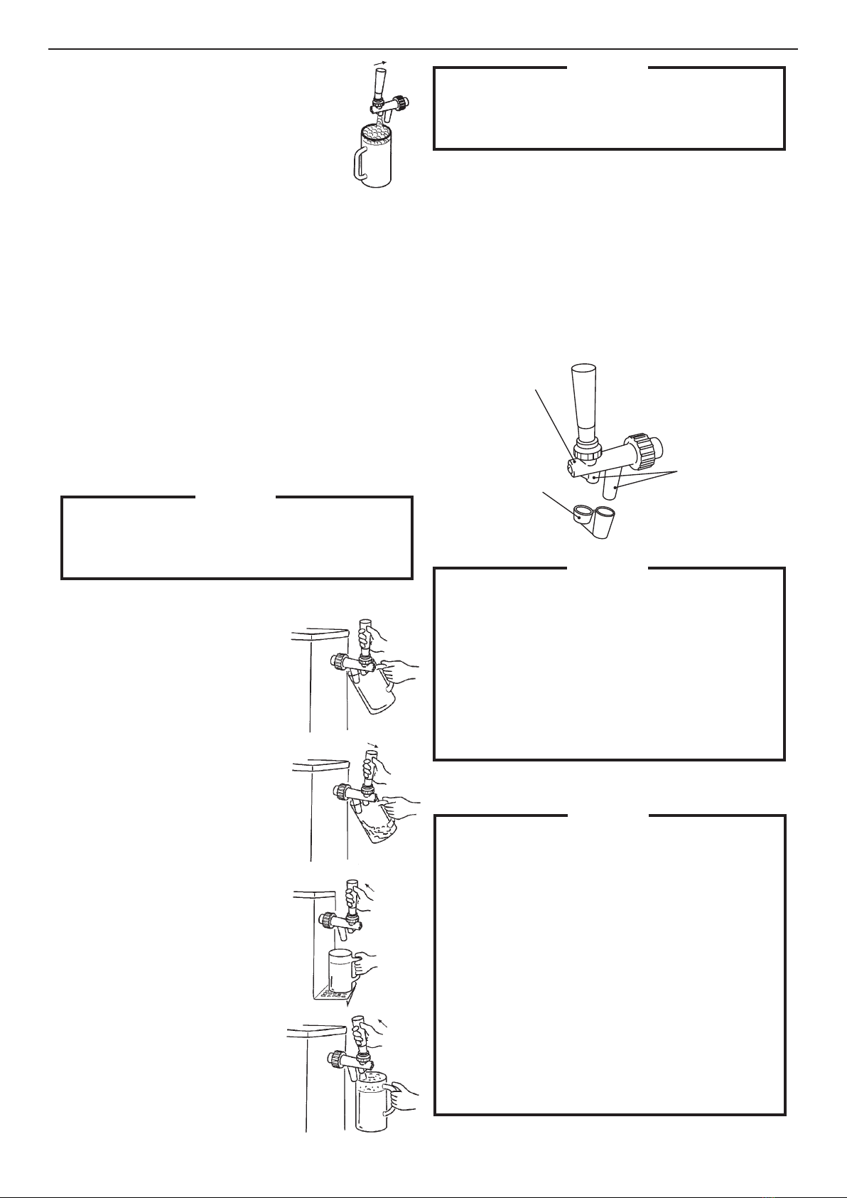
1)Checkthattheregulatoradjustdialissettotheappropriate
pressurespeciedbythebeercompany.
2)Check that the beer tap lever is closed. Opening the keg coupler
withthebeertapleveropenwillcausebeertosplashout.
3)Openthekegcoupler.
4)Set a mug to receive beer, and push the beer tap lever hard to
theback(foamposition).Keeppushingittodispensefoam.When
themugishalflledwithfoam,movetheleverbacktoitsoriginal
positiontostopfoam.
5)Waitformorethan1minuteafterstep4)tosettlebeerinthecircuit.
6)Setanothermug,andpullthebeertaplevertowardyouto
dispensebeer.Keepdispensingbeeruntilfoamturnsintoliquid.
7)Checkthekegcouplerandkegconnectionandthebeerhosejoints
forbeerleaks.
IMPORTANT
Frequently dump water and beer from the drain pan. The
coolingwaterinthewatertankwillincreaseinvolumebytaking
moisturefromtheair,andcomeoutthroughtheoverowhose
intothedrainpan.Ifleftasitis,waterwillowoutofthedrain
panontotheoor.
[c] DISPENSING BEER
3)Todispensefoam,pushthebeertapleverhard
toward the unit from the stop position. To stop
foam,movetheleverbacktoitsoriginalposition.
IMPORTANT
Ifthebeercircuitisnotflushedwithbeerremainingonthe
beertap, thevalve shaftjams insidethe beer tap, resulting in
unavailable,unstable,orcontinuousdispensingactions.Inthis
case,disassembleandcleanthebeertapinaccordancewith“III.
5.DISASSEMBLYANDCLEANINGOFBEERTAP(WEEKLY)”.
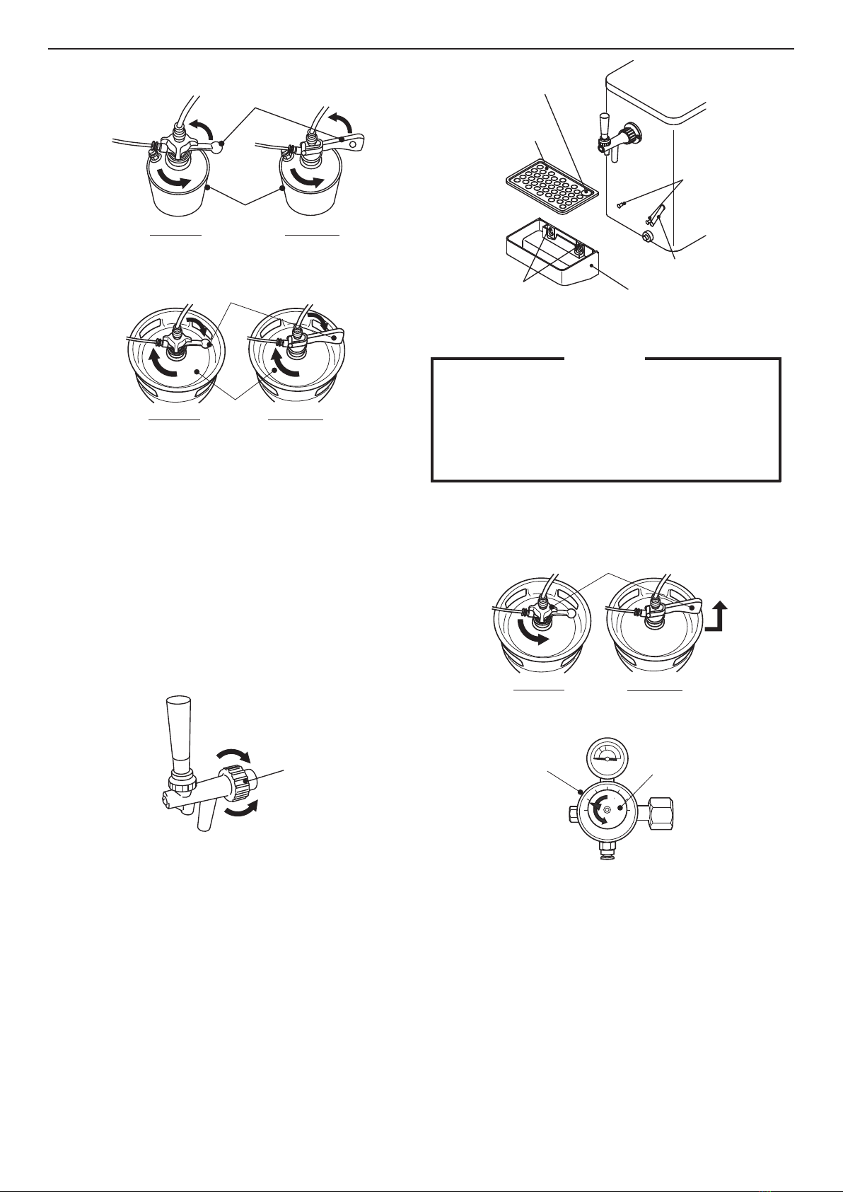
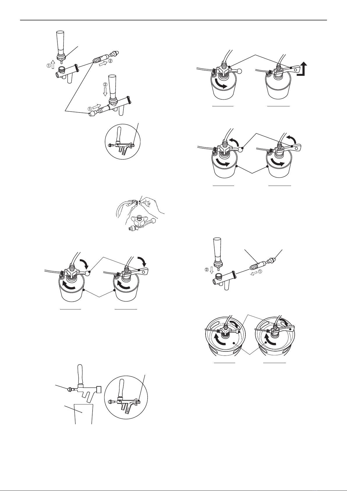
[d] END OF OPERATION
1)Closethekegcoupler,andremoveitfromthekeg.Flushthebeer
circuit according to “III. 1. BEER CIRCUIT (DAILY)” and “III. 4.
CLEANINGBEERCIRCUITWITHSPONGE(WEEKLY)”.
2)Turntheregulatoradjustdialcounterclockwiseto“0”.
3)ShutofftheCO2gascylinderbyturningthemainvalveclockwise.
4)Wipe moisture from the nozzle end. Wash the nozzle cap clean,
andfititonthenozzle.Thenozzlecapmustberemovedand
storedinacleanplaceduringoperation.
Fiton
Beertap
Nozzle
Nozzlecap
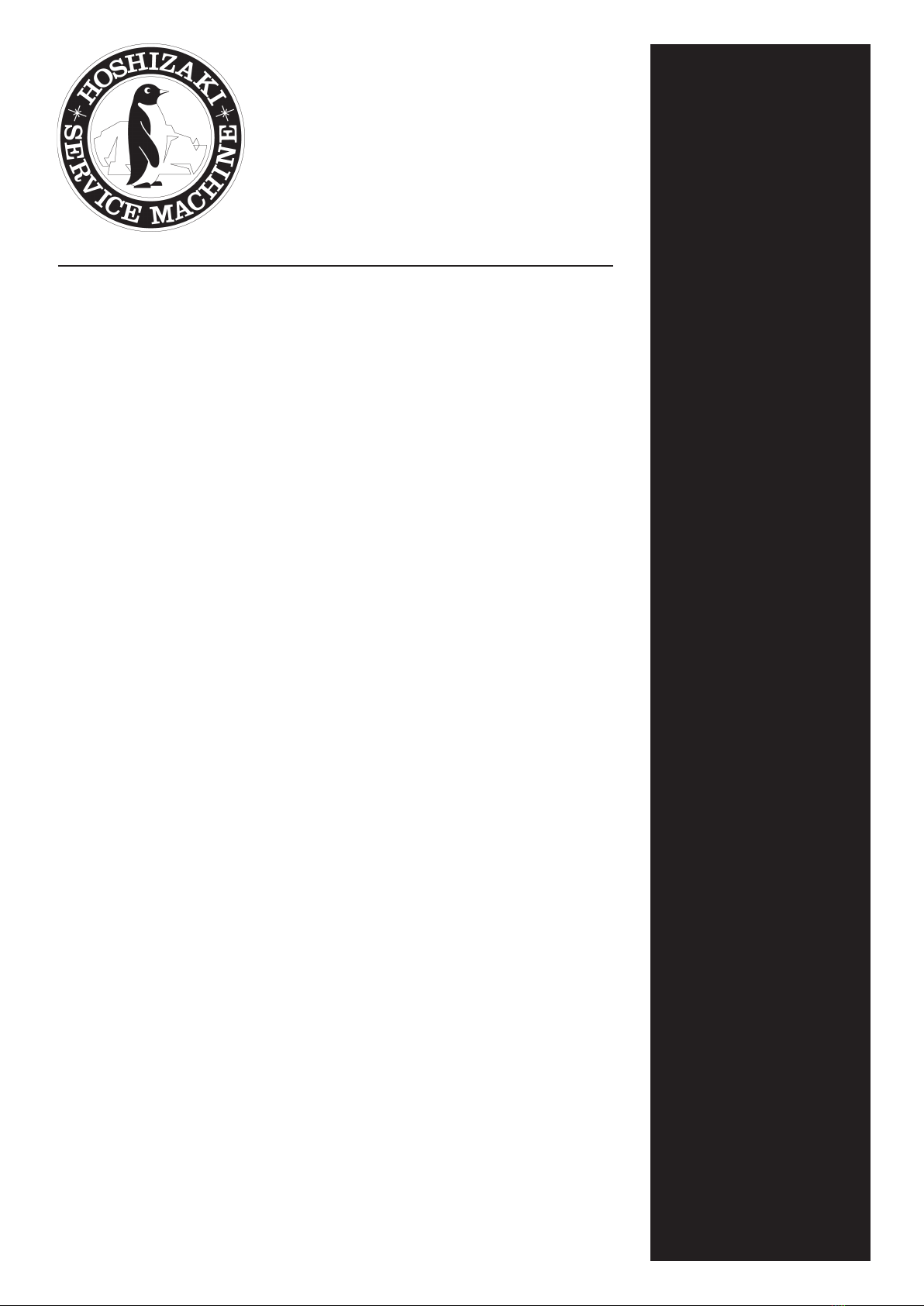
1)Tiltacleanmugatan angle of45°,and
placeitsinnersurfaceincontactwiththe
liquidnozzleofthebeertap.
2)Pullthebeertaplevertowardyouto
dispense beer over the inner surface of
themug.
3)Afterdispensingaspecificamountof
beer,movethebeertapleverbacktoits
originalpositiontostopbeer.
4)Toadd foam,push thebeer tap leverto
the back. Foam will keep coming out of
thefoamnozzleofthebeertapwhilethe
leverispushed.Tostopfoam,movethe
leverbacktoitsoriginalposition.
IMPORTANT
1. To preventexcessive mixtureof CO2 gasin draftkeg beer,
besure toclose themain valveof theCO2 gascylinder at
theendofoperation.
2.Theaccessorynozzlecapprotectsthebeertapnozzle
againstdustorinsectswhilethedispenserisnotused.
Alwayscapthenozzleattheendofoperation.
3. When the keg coupler on the keg is closed, gas may stay
insidethebeercircuit.Topreventexcessivefoamingor
improper dispensing actions, lead beer into the beer circuit
untilgascomesoutofthebeertapbeforestartingoperation
onthefollowingday.
III. MAINTENANCE
IMPORTANT
1.Afterclosingtime,besuretocarryoutthefollowing
maintenanceprocedures.
2.Followthemaintenanceinstructionsbelowwhenever
considerednecessary.
3. Incleaningoperations,becarefulnotto loseanyparts.The
unitwillleakwaterorfailtodispenseproperly.
4.Alwaysusecleanhandsandclothstoconductcleaning
operations.
5. Asasanitizer,useamixtureofwarmwater(30-40°C)and
10 mL of 10% invert soap (benzalkonium chloride). Before
usingthesanitizer,thoroughlyreadtheinstructionsprovided.
6.Topreventdamagetotheplasticsurfaces,donotuse
thinner,benzine,petroleum,soappowder,polishingpowder,
alkaline detergent, scrub brush, and especially cleanser for
useonfansandcookingranges.Also,topreventcorrosion,
donotuseachlorinebleach(sodiumhypochlorite).

6
1. BEER CIRCUIT (DAILY)
IMPORTANT
Use the cleaning tank specied by the beer company. Follow
theoperatinginstructionsprovidedonthecleaningtank.
1) Closethebeercircuitbeforeushing.
Rotarytype:Turnthekegcouplerhandlecounterclockwiseuntilit
stops.
Vertical type: Unlock and lift the keg coupler handle all the way
up.
Kegcouplerhandle
Rotarytype Verticaltype
Regulator Adjustdial
2) Turntheregulatoradjustdialcounterclockwiseto“0”.
3) ShutofftheCO2gascylinderbyturningthemainvalveclockwise.
4) Movethebeertaplevertowardyoutodispensebeerremainingin
thecircuit.
5) Whennomorebeercomesout,movetheleverbacktoitsoriginal
position.
6) Turn the keg coupler counterclockwise, and remove it from the
keg.
7) Washthecleaningtankthoroughly,andllitwithtapwater.Adirty
cleaningtankwillcontaminatethebeercircuit.
8) Attachthekegcoupleronthecleaningtank.
10) Turntheregulatoradjustdial,andadjustthegaspressureto0.15
MPaortheallowablerangespeciedonthecleaningtank.
11) Openthebeercircuit.
Rotarytype:Turnthekegcouplerhandleclockwiseuntilitstops.
Vertical type: Push downthe keg couplerhandle until it locksin
place.
12) Checkifthecleaningtankisprovidedwithasiphontubeinside.
If no siphon tube is provided: Turn down the ferrule of the
cleaningtank(upsidedown).
Ifsiphontubeisprovided:Turnuptheferruleofthecleaningtank.
13) Prepareaplasticbuckettoreceivecleaningwater.Movethebeer
tap lever toward you to dispense water. When beer turns into
water,movethelevertothebacktoushthefoamcircuit.
14) When no more water comes out, turn the regulator adjust dial
counterclockwise to “0”. Leave the beer tap open. Shut off the
CO2gascylinderbyturningthemainvalveclockwise.Whenthe
gasstops,movethebeertapleverbacktoitsoriginalpositionto
closethebeertap.
15) Closethebeercircuit.
Rotarytype:Turnthekegcouplerhandlecounterclockwiseuntilit
stops.
Vertical type: Unlock and lift the keg coupler handle all the way
up.
Kegcoupler
Keg
Rotarytype Verticaltype
Kegcoupler
Cleaningtank
Rotarytype Verticaltype
Kegcouplerhandle
Rotarytype Verticaltype
Siphontube
Bucket
Kegcouplerhandle
Rotarytype Verticaltype
9) Checkthatthebeertapisclosed,andopentheCO2gascylinder
byturningthemainvalvetwoorthreetimescounterclockwise.

7
16) Turn the keg coupler counterclockwise, and remove it from the
cleaningtank.
Kegcoupler
Rotarytype Verticaltype
Cleaningtank
17) Attachthe kegcoupler onthekeg byturning itclockwiseuntil it
stops.
Kegcoupler
Keg
Rotarytype Verticaltype
18) Wash the cleaning tank thoroughly, dry it well, and use the cap
providedtoshutoutdust.
19) Wipe moisture from the beer tap nozzle. Wash the nozzle cap
clean,andtit onthenozzle.Thenozzlecapmust beremoved
andstoredinacleanplaceduringoperation.
2. BEER TAP (DAILY)
1) Loosenthe union nutof the beertap by turningit clockwise, and
removethebeertap.
2) Tilt the beer tap lever toward you, and run tap water through the
beertap.
3) Retthebeertapbyturningtheunionnutcounterclockwise.
Unionnut
Loosen(clockwise)
Tighten(counterclockwise)
3. DRAIN PAN (DAILY)
Wipethedrainpansurfacesbyusingaclothcontainingwarmwater(30
-40°C)withinvertsoap.After3minutes,wipeoffanyremainingsoap
withacleanclothcontainingcoldorwarmwater.Cleanthedrainpan
whenevernecessary.
1) Removethedrainboard,andliftthedrain pantoreleaseits
mounting holes from the mounting screws. Be careful not to spill
waterandbeercollectedinthedrainpan.
2) Dump water and beer, and wash the drain board and drain pan
withtapwater.
3) Liftthedrainpantohookthemountingholesonthemounting
screws,andsetthedrainboardonthedrainpan.
4) Check that the overow hose goes through the hole in the drain
boardandcandrainwaterintothedrainpan.
Mountingscrew
Throughholefor
overowhose
Mountinghole
Overowhose
Drainboard
Drainpan
4. CLEANING BEER CIRCUIT WITH SPONGE (WEEKLY)
IMPORTANT
1. Storetheusedcleaningspongeforlateruse.
2. Usethecleaningtankspeciedbythebeercompany.Follow
theoperatinginstructionsprovidedonthecleaningtank.
3.Useoneofthecleaningspongesprovided.Toprevent
clogging,do notuse morethan onesponge orany sponge
otherthanthoseprovided.
1) Closethebeercircuitbeforeushing.
Rotarytype:Turnthekegcouplerhandlecounterclockwise.
Vertical type: Unlock and lift the keg coupler handle all the way
up.
Kegcouplerhandle
Rotarytype Verticaltype
Regulator Adjustdial
2) Turntheregulatoradjustdialcounterclockwiseto“0”.
3) ShutofftheCO2gascylinderbyturningthemainvalveclockwise.
4) Movethebeertaplevertowardyoutodispensebeerremainingin
thecircuit.
5) Whennomorebeercomesout,movetheleverbacktoitsoriginal
position.
6) Loosentheunionnutofthebeertapbyturningitclockwise,and
removethebeertap.
7) Loosenthecapnutofthebeertap,anddisassemblethebeertap.
Fitthevalveshaftintheoppositedirectionasshownbelow,and
tightenthecapnut.(Thisistopreventthecleaningspongefrom
cloggingthebeertap.)

8
8) Attach the beer tap on the unit by
tighteningtheunionnut.
9) Prepareaplasticbucketunderthe
beertaptoreceivedrainwater.
10) Wash the cleaning tank thoroughly,
andllitwithtapwater.
11) Removethequickbeerhosejoint
fromthekegcoupler,putthecleaning
sponge into the joint, and refit it on
thekegcoupler.
Capnut
[NormalOperation]
[SpongeCleaning]
Valveshaft
Cleaningsponge
Cleaningsponge
12) Attachthekegcoupleronthecleaningtank.
13) OpentheCO2gascylinderbyturningthemainvalvetwoorthree
timescounterclockwise.
14) Turntheregulatoradjustdial,andadjustthegaspressureto0.15
MPaortheallowablerangespeciedonthecleaningtank.
15) Thecleaningspongewillcomeoutwithwater.
Kegcoupler
Rotarytype Verticaltype
Cleaningtank
Valveshaft
Cleaningsponge
Bucket
18) Turn the keg coupler counterclockwise, and remove it from the
cleaningtank.
22) Attachthekegcoupleronthekeg.
Kegcouplerhandle
Rotarytype Verticaltype
Kegcoupler
Rotarytype Verticaltype
Cleaningtank
19) Recoverthecleaningspongefromthebucket.
20) Repeattheabovesteps10)to16)untilclearwatercomesoutof
thebeertap.
21) Remove the beer tap, set the valve shaft in its normal position,
andretthebeertapontheunit.
Kegcoupler
Keg
Rotarytype Verticaltype
23) Wash the cleaning sponge thoroughly with tap water. Drain and
storeitforlateruse.
5. DISASSEMBLY AND CLEANING OF BEER TAP
(WEEKLY)
1) Closethebeercircuitbeforeushing.
Rotarytype:Turnthekegcouplerhandlecounterclockwise.
Verticaltype:Unlockandliftthekegcouplerhandleallthewayup.
Valveshaft
Hole
16) When the cleaning sponge and water have come out, turn the
regulator adjust dial counterclockwise to “0”. Shut off the main
valveoftheCO2gascylinder.Waituntilgasstopsowingoutof
thebeertap.
17) Closethebeercircuit.
Rotarytype:Turnthekegcouplerhandlecounterclockwise.
Vertical type: Unlock and lift the keg coupler handle all the way
up.

9
2) Turntheregulatoradjustdialcounterclockwiseto“0”.
3) Move the beer tap lever toward you to dispense beer remaining
in the circuit. Loosen the union nut of the beer tap by turning it
clockwise,andremovethebeertap.
4) Loosenthecapnutofthebeertap,andremovethelever.
5) Removethevalveshaftfromthebeertap.
Valveshaft
Capnut
Lever
6) Cleanthebeertapandvalveshaftbyusinganeutraldishwashing
detergentandtheaccessorycleaningbrush.
7) Use the accessory brush (S) to clean the two small holes in the
beertap.
8) Rinsethebeertapthoroughlywithcleanwater.
Valveshaft
Hole
Brush(S)
Smallhole
Smallhole
Beertapcrosssection
6. KEG COUPLER (WEEKLY)
Cleanthekegcouplerinaccordancewiththebeercompany’s
instructionmanual.
7. EXTERIOR (WEEKLY)
The stainless steel exterior also needs cleaning to prevent possible
corrosion.Wipewithasoftcloth.Useasoftdampclothcontaininga
neutraldishwashingdetergenttowipeoffdirtbuildup,andremoveany
remainingdetergent.Cleantheexteriorwhenevernecessary.
8. AIR FILTER (BIWEEKLY)
1) Removethedrainpan.
2) Pull the air filter slightly toward
you.Pushitdown,andpullitout.
3) Washthe air lter with cold water
orwarmwatercontaininganeutral
dishwashingdetergent.Becareful
nottobreakthenet.Afterusing
adetergent,rinsetheairfilter
thoroughly.Dryitintheshade. Drainpan
Airlter
4) Fittheairlterintothelterguideatthebottom,andslideittothe
back.
5) Retthedrainpan.
IMPORTANT
1.Whentheairfilteriscloggedwithdirtanddust,theunit
cannotoperateproperly.
2. Do not operate the unit with the air filter removed. The
condenserwillclogeasily.
3.To prevent deformation, do not wash the air filter with hot
waterabove40°C.
4. Donothitordrop thedrain panand airlter whilecleaning
them.
IV. INSPECTION
1. GAS HOSE AND BEER HOSE (MONTHLY)
Check the gas and beer hoses for damage, deformation, and water
leak marks (stains). If any problem is found, contact an authorized
Hoshizakiservicecompany.
2. ATTACHMENT PLUG AND POWER CORD (ANNUALLY/
BIANNUALLY)
CAUTION
1.Checkperiodicallythat theattachmentplugbladesand
theirvicinityarefreeofdustandthattheattachmentplugis
securelypluggedintothereceptacle.Dusty bladesorloose
connectionmaycauseelectricshockorre.
Kegcouplerhandle
Rotarytype Verticaltype
9) Assemblethebeertapproperlybypositioningtheholeinthevalve
shaft(largerholefacingup).

10
2. Donotdamagethepowercord.Itshouldnotbeadditionally
processed, jerked, bundled, weighed down or caught in. It
couldcauseelectricshockorre.
3. The unitmust have aseparate power supply.Branching off
thepowercord,usinganextensioncord,orsharingasingle
powersupplywithotherappliancesmayresult in electric
shock,heatgenerationorre.
Checkthat:
* Theattachmentplugbladesandtheirvicinityandthereceptacleare
freeofdust.Cleanthemifnecessary.
* The attachment plug and power cord are not damaged, weighed
downorcaughtin.
* Theattachmentplugispluggedintoaseparatereceptacle.
3. COOLING WATER (BIANNUALLY)
1) Unplugtheunit.
2) Removethetopcoverandinnercover.
3) Checkthatthecoolingwaterlevelisabout2cmbelowthetopof
the water tank (DBF-25SB-AU) or up to the standard water level
marked on the tank (DBF-43SB-AU). If it is insufcient, rell the
watertankwithtapwater.Refreshthecoolingwatertwiceayear.
Torefreshthecoolingwater:
4) Removethedrainpan.
5) Preparealargecontainertoreceivedrainwater[about6L(DBF-
25SB-AU)or8L(DBF-43SB-AU)inicestorage].Removethedrain
plug,anddrainthewatertank.Afterthecoolingwaterhasdrained
out,retthedrainplug.
6) Refillthewatertankaccordingto“I.5.[a]COOLINGWATER
SUPPLY”.
7) Retthetopcoverandinnercover.
8) Plugintheunit.
IMPORTANT
Dust,bacteria,andmoistureintheairmaycausecontamination
or reduction in conductivity of the cooling water. To prevent
cloggingoftheoverowhoseorinadequateicestorage,refresh
thecoolingwatertwiceayear.
Ifthecoolingwaterconductivityreducesandnoiceisproduced
in the water tank, fill 1/3 (2 g) of the nozzle cap with baking
soda.Donot useanexcessiveamount ofbakingsoda or any
othersubstancessuchassalt,vinegar,andjuice.Theywill
corrodethestainlesssteelandcoppertubesandcausefailure.
1/3(2g)
Nozzlecap(accessory)
V. LONG STORAGE, RELOCATION, DISPOSAL,
TRANSFER
* When shutting down the unit for more than a week, carry out the
followingmaintenanceprocedurestocleananddrainthebeer
circuitandtokeeptheunitclean:
III. 4.CLEANINGBEERCIRCUITWITHSPONGE
5.DISASSEMBLYANDCLEANINGOFBEERTAP
6.KEGCOUPLER
7.EXTERIOR
8.AIRFILTER
Drainthewatertankaccordingto“IV.4.COOLINGWATER”.It
takesafewdaystomelticeleftinthewatertank.Aftermeltingall
theice,drainthewatertankagain,anddrythetankinterior.
* Incaseofrelocationordisposaloftheproduct,contactan
authorizedHoshizakiservicecompany.
* When sellingor transferringthis product,tape thisinstruction
manualtotheexteriortoprovidethenewownerwithinformationon
safeandproperuseoftheproduct.
This manual suits for next models
1
Table of contents
Other Hoshizaki Kitchen Appliance manuals