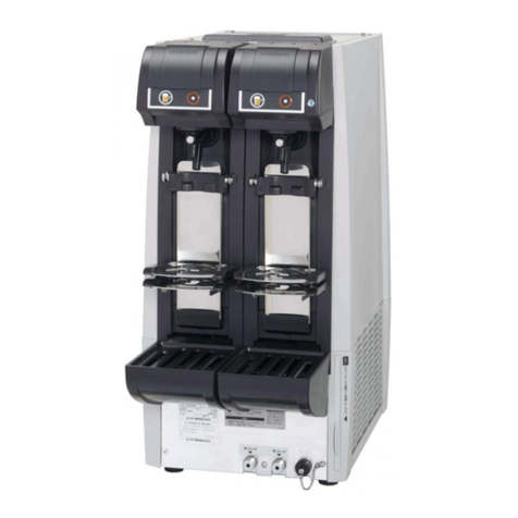
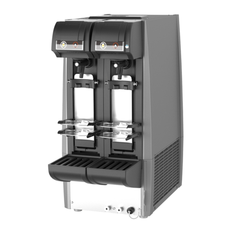
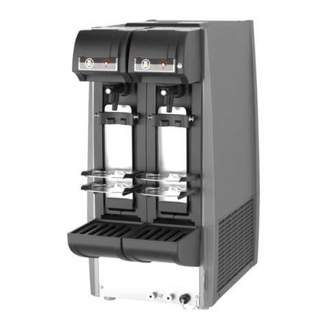
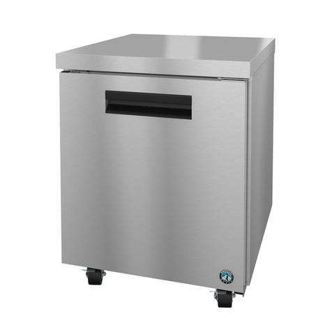
Hoshizaki Ice Bank Beer System User manual

www.lancerbeverage.com
Ice bank Beer System
Operation Manual

Ice Bank Beer System Manual
www.lancerbeverage.com Page 2 of 17
Hoshizaki Lancer reserve the right to change specifications without notice. Part No: 68000213
Images are for illustration purposes only as product may vary. No 072-2 – 26 May 2020
Table of contents
1. Overview of your Ice Bank Beer System........................................................................... 3
Keg Tapping .................................................................................................................................... 3
Founts .............................................................................................................................................. 3
Ice bank Chiller................................................................................................................................ 3
2. Basic Cellar Procedures...................................................................................................... 4
Changing a Keg............................................................................................................................... 4
End of Trade Procedures ............................................................................................................... 4
Gas System ..................................................................................................................................... 4
Recommended Maintenance Schedule ........................................................................................ 4
3. Typical Service Issues......................................................................................................... 5
Beer is Pouring Heady.................................................................................................................... 5
Beer is not Pouring.......................................................................................................................... 5
Beer is Pouring Flat......................................................................................................................... 5
Beer is Pouring Slow....................................................................................................................... 5
Loss of Condensation on the Founts............................................................................................. 6
Ice bank Tank – Temperature Increase ........................................................................................ 6
Using Excessive Amounts of Gas.................................................................................................. 6
4. Cleaning the System............................................................................................................ 6
Daily Cleaning ................................................................................................................................. 6
Weekly Cleaning ............................................................................................................................. 7
Monthly Cleaning and Checks ....................................................................................................... 8
Yearly Cleaning ............................................................................................................................... 9
5. Gas System ........................................................................................................................... 9
Safety with CO2: ............................................................................................................................. 9
Leak Detection............................................................................................................................... 10
5.2.1 Drop Test ............................................................................................................ 10
5.2.2 Finding the leak................................................................................................... 10
6. Gas Types ........................................................................................................................... 11
Carbon Dioxide (CO2) .................................................................................................................. 11
Mixed Gases (CO2/N2) ................................................................................................................ 11
Cylinder Pressure.......................................................................................................................... 11
7. AS5034 CO2 Safety Equipment ........................................................................................ 11
Carbon Dioxide (CO2) .................................................................................................................. 11
Properties....................................................................................................................................... 11
8. Certificate of Warranty....................................................................................................... 12
9. Install Technicians Checklist............................................................................................ 13
10. Commissioning Sheet ....................................................................................................... 14
11. Compliance Certificate ...................................................................................................... 15
12. AS5034 Onsite Risk Assessment..................................................................................... 16

Ice Bank Beer System Manual
www.lancerbeverage.com Page 3 of 17
Hoshizaki Lancer reserve the right to change specifications without notice. Part No: 68000213
Images are for illustration purposes only as product may vary. No 072-2 – 26 May 2020
1. Overview of your Ice Bank Beer System
Ice bank Beer Systems are designed as a high performance / low energy solution to draught
beer.
Your installation has been based on the information provided on the number of dispense points,
site conditions, and keg turnover. This ensures a balanced reticulation system capable of
handling your maximum expected volume of trade.
Along with this manual we have supplied a Cellar Log Book. A maintenance program should be
in place and a log book kept covering cleaning schedule & all other activities relevant to draught
beer. Doing so will result in excellent beer presentation, with absolutely minimum waste. A
hygienic system is a MUST!!
Included at the back of this manual are your:
Installation Checklist
Commissioning Sheet.
Certificate of Compliance.
Outlet Risk Assessment.
Keg Tapping
•
The keg is tapped by connecting the coupler to the keg. The coupler is then engaged.
Beer is distributed to the correct tap.
•
CO2 Beverage Gas is supplied to each keg, as the energy to move the beer from the
keg to the glass while maintaining the correct CO2 percentage in the beer.
Founts
Beer Founts are available in a variety of shapes and sizes. The heat load on each fount
varies according to its size. The riser lines are banded to and insulated with the
recirculation lines to the fount to ensure consistently cold dispense temperature.
Ice bank Chiller
The heart of the system is the Ice bank Chiller, located under the bar. It contains stainless
steel beer coils submerges in an ice bath to chill the beer. A pump recirculates the iced
bath water from the tank up through the font before returning to the tank for re-cooling.
Ice banks are sized in Kg’s of ice that builds on the refrigeration coil – e.g. 15kg, 25kg,
and 35kg.
•
As altering ambient conditions and keg temperatures have a dramatic effect on the
cooling capabilities of the system, we allow extra tolerance when calculating “Heat
Loads”. This assists in offering maximum performance through the most extreme
conditions.
For any issues not covered in this manual please contact Hoshizaki Lancer on
1300 551 361

Ice Bank Beer System Manual
www.lancerbeverage.com Page 4 of 17
Hoshizaki Lancer reserve the right to change specifications without notice. Part No: 68000213
Images are for illustration purposes only as product may vary. No 072-2 – 26 May 2020
2. Basic Cellar Procedures
Changing a Keg
1. Disengage the handle of the Keg Coupler on empty keg.
2. Disengage the Drop Lead from Keg Coupler.
3. Remove the Coupler from the Keg.
4. Check the integrity of the keg seal and spray with sanitizer
5. Place Keg Coupler on the new keg and fit the Drop Lead.
6. Engage the Handle.
7. Check the beer flow through the tap, pouring until it is completely full of beer. ”
End of Trade Procedures
•
Disengage keg couplers handles on kegs.
•
Leave drop leads connected to keg coupler.
•
Turn off CO2 supply.
Gas System
•
This Gas System meets AS5034 and your Certificate of Compliance is completed on
Appendix C in this manual.
•
The system is set up for a regulator to supply Beverage Gas CO2 into the keg. The
purpose of the CO2 is twofold. The first is to provide the energy to dispense the beer
and the second is to provide a blanket of CO2 on top of the beer to ensure balance of
correct CO2 % is maintained in the beer. This is crucial.
•
For Nitrogenous Beers and Stouts a separate Regulator will supply a Stout mix which
is70% N2/ 30% CO2 - blend. Nitrogenous Beers when dispensed through a restrictor
plate in the tap will produce the tight thick head associated with Stouts.
Recommended Maintenance Schedule
Lancer offers a Preventative Maintenance Program for all Quarterly, 6 month & 12 month
checks. Please contact the Lancer National Service Centre on 1300 551 361 to obtain a
quote. You should check over all the cellar equipment on a weekly basis. Worn O-rings
and check valves can be easily replaced and will stop costly leaks or frustration with
using equipment.
Spare Parts can be ordered by:
•
Phone: 1300 551 361
•
Email: Lancerservice@lancerworldwide.com
•
Website:www.lancerbeverage.com
Daily
•
Check gas system for leaks
•
Check beer system for leaks
•
Check operation of beer taps
•
Inspect and replace as necessary all visible O-rings
Weekly
•
Chemically clean beer lines and equipment as required
•
Rinse any external residues from taps, couplers and fittings with hot water
•
Check temperature of dispensed beer (0.5°C to 3°C is acceptable)
•
Check operation of glass cleaning equipment

Ice Bank Beer System Manual
www.lancerbeverage.com Page 5 of 17
Hoshizaki Lancer reserve the right to change specifications without notice. Part No: 68000213
Images are for illustration purposes only as product may vary. No 072-2 – 26 May 2020
Quarterly
•
Service beer taps, keg couplers and other dispense equipment.
•
Chiller and other systems as per manufacturers recommendations
•
Check water level in tank
Half yearly
•
Have the gas system inspected as per AS5034
Annually
•
Have the refrigeration system serviced
•
Have the gas system inspected as per AS5034
3. Typical Service Issues
Beer is Pouring Heady
•
Faulty Keg Coupler - If the seal on the shaft of the coupler fails it will allow CO2 past
and into the drop lead, filling the line with CO2.
•
Beer temperature is too warm - check the Ice bank Bath Temperature. – Refer 6.6 –
Ice bank Bath temperature increase.
•
Over Carbonated Beer – Check CO2 pressures are as per settings recorded on the
Commissioning Sheet. The keg may have also been tapped for too long.
Beer is not Pouring
•
Keg Coupler is not engaged - check the keg coupler in the cool-room to see if the
coupler handle is fully engaged. Damaged handle pivots sometimes prevent this...
•
Gas System turned OFF - check if the bottle is turned on and ensure there is CO2 in
the bottle.
•
Beer Frozen in the Stainless Steel Coils – Check the coils are clear of the Ice bank. If
it is in the ice, turn off the unit and call your refrigeration mechanic. .
Beer is Pouring Flat
•
Beer temperature is too cold - Indicated by having to really work the beer to form a
head. If beer temperature in the glass is too cold, the CO2 will want to stay in
solution.
•
Beer glasses are too cold - The beer glasses are being kept in sub zero conditions -
Increase temperature of the Glass Chillers.
•
Beer glasses are dirty - The beer pours into the glass fine but the head does not last
very long - check your cleaning procedure of glasses.
•
Faulty Keg – The seal on the keg has let all CO2 out and the beer in the keg is flat.
Beer is Pouring Slow
•
Gas System is turned OFF - check to see if the bottle is turned on.
•
Gas Bottle Empty - Confirm there is adequate pressure in the bottle.
•
Beer may be starting to freeze - usually only happens with the Low Alcohol Beers
with ice crystals forming. Check the coils are clear of the Ice bank. If it is in the ice,
turn off the unit and call your refrigeration mechanic.

Ice Bank Beer System Manual
www.lancerbeverage.com Page 6 of 17
Hoshizaki Lancer reserve the right to change specifications without notice. Part No: 68000213
Images are for illustration purposes only as product may vary. No 072-2 – 26 May 2020
Loss of Condensation on the Founts
•Ice bank Tank has increased in Temperature - Check power supply to chiller if OK, check the
following :
1. Check the water level in the Ice bank tank.
2. Check for Ice In the Ice bank tank.
3. Pump has been Turned Off - check to see if Agitator/pump is running on the Ice bank
Tank. If the pump is not working & pump is turned on - contact Lancer Service on 1300
551 361 immediately.
•Change of Environment in the Bar area - Changing weather conditions effect the formation of
condensation. Warm breezes in summer and no humidity in winter have a deteriorating effect.
•Dirty / greasy font - If dirty hands have been rubbing the font it may affect the formation of
condensation. Clean with a dry clean cotton cloth to remove any dirt or grease.
Ice bank Tank – Temperature Increase
•No power to Tank/Ice bank control.
•Tank has recently been filled with warm water.
Using Excessive Amounts of Gas
•Gas leak on system - Check over gas system as per Weekly Checks/ Gas Leaks
•Higher than usual turnover of kegs - this is to be expected.
4. Cleaning the System
Regular cleaning of the whole beer system is extremely important, if this is not performed bacteria,
yeast, mould, etc. will build up and quickly degrade the quality and taste of the beer.
Daily Cleaning
Good food hygiene practices should be a part of the daily routine – spills wiped up, empty
containers disposed of, and equipment kept neat and orderly.
Lift the keg coupler handle to disengage, but do not remove, to prevent over carbonation
at the end of the trading day.
Beer Tap
•With keg coupler disengaged move the beer tap handle towards you to
dispense any beer remaining in the circuit.
•Disengage the tap from the fat-lock adaptor. Loosen the coupling nut of the
beer tap by turning it clockwise and remove the beer tap.
•Tilt the beer tap lever towards you and run tap water through the beer tap.
•Ensure the coupling seal is in place and refit to the beer tap by turning the
coupling nut counter clockwise. Engage the tap into the fat -lock adaptor.
Exterior Cleaning
•Wipe the stainless steel lid, drip tray, and the fount with a soft damp cloth containing a
neutral dishwashing detergent to wipe off any dirt build-up, and remove any remaining
detergent with a clean soft cloth.

Ice Bank Beer System Manual
www.lancerbeverage.com Page 7 of 17
Hoshizaki Lancer reserve the right to change specifications without notice. Part No: 68000213
Images are for illustration purposes only as product may vary. No 072-2 – 26 May 2020
•Clean the exterior of the chiller whenever necessary.
At the start of the next trading day, push down on the keg coupler handle to re-tap the keg.
Move the beer tap lever towards you and dispense product until you have clean product i.e.
no froth.
Weekly Cleaning
As per cleaning instructions, ensure weekly sanitisation of the whole beer system is carried
out, including keg coupler, beer line, chiller coils and tap.
The following instructions are for general applications, breweries may offer alternative
cleaners and procedures.
Lift the keg coupler handle to disengage.
Beer lines Cleaning
Warning Only trained personnel should undertake the cleaning process for this
equipment.
Warning
Most commercial beer line chemicals are classified as hazardous if
ingested or when in contact with skin or the eyes. Take proper
precautions when handling and wear protective clothing and
goggles. Read and understand the handling procedures for the
chemicals used.
•Thoroughly rinse a washout canister and fill with potable water.
•A 5L washout canister is available from Hoshizaki Lancer. Before opening, vent the
canister by pulling the relief valve ring.
•Turn the keg coupler counter clockwise and remove it from the keg.
•Check the tap is closed. Connect the keg coupler to the wash out canister and push down
on the keg coupler handle to engage.
•Place a bucket under the tap, pull the tap handle towards you and allow water to run
though the beer line until the water runs clear at the tap.
•Disconnect the keg coupler from the washout canister and depressurise the canister.
•Prepare the sanitising solution according to the manufacturer’s directions and fill the
washout canister with 3 to 4 litres of the sanitiser.
•Connect the keg coupler to the washout canister and push down on the keg coupler
handle to engage.
•Place a bucket under the tap, pull the tap handle towards you and allow sanitiser to run
though the beer line.
•If using Hoshizaki Beer line cleaner, the pink Hoshizaki chemical will indicate when
sanitiser has reached the tap.
•Leave the sanitising solution in the beer line as per the manufacturer’s recommendations.
•For Hoshizaki Beer line cleaner, leave for 2hrs, preferably overnight.
•After the recommended time has elapsed, disconnect the keg coupler from the washout
canister and depressurise.
•Thoroughly rinse and refill the washout canister with clean water.

Ice Bank Beer System Manual
www.lancerbeverage.com Page 8 of 17
Hoshizaki Lancer reserve the right to change specifications without notice. Part No: 68000213
Images are for illustration purposes only as product may vary. No 072-2 – 26 May 2020
•Reconnect the keg coupler and run sufficient water through the beer line to ensure that all
the sanitiser has been removed from the lines. Toggle the tap on and off while flushing.
•Disconnect the keg coupler from the washout canister and depressurise the canister.
•Connect the keg coupler to the beer keg and push down on the keg coupler handle to
engage.
•Open the tap and draw through beer. Allow the system to settle for 10 minutes then open
the tap again and pour off until beer is clear.
•The system is now ready for trading.
Beer Tap
•With keg coupler disengaged move the beer tap handle towards you to
dispense any beer remaining in the circuit.
•Disengage the tap from the fat-lock adaptor. Loosen the coupling nut of the
beer tap by turning it clockwise and remove the beer tap. (Fig. 1).
•Loosen the cap nut of the beer tap and remove the handle (Fig. 2).
•Remove the valve shaft from the beer tap (Fig. 3).
•Clean the beer tap and valve by using a neutral dishwashing detergent and
the accessory cleaning brush.
•Rinse the beer tap thoroughly with clean water.
•Assemble the beer tap properly by positioning the hole in the valve shaft with
the handle.
•Refit the beer tap by turning the union nut counter clockwise. Refit to fount.
•At the start of the next trading day, push down on the keg coupler handle to
re-tap the keg. Move the beer tap lever towards you and dispense beer until you have
clean beer i.e. no froth.
Keg Coupler
Clean the keg coupler in accordance with the beer company’s instruction manual.
Monthly Cleaning and Checks
Cleaning the condenser
Disconnect the machine’s electrical plug from the mains outlet before cleaning the condenser.
Use a brush to remove any dust or foreign matter, which may prevent air from circulating
around the condenser fins.
Caution: always wear protective gloves for this operation.
Overflow
Check that the hole and the overflow and drip tray outlet pipes are not blocked with dirt or ice.
Check the tank water level, fill if necessary.
Checking efficiency
Check that the condenser motor fan is free from any obstructions and dust. Check that the
agitator blade has no scaling due to the limestone in the water. Remove any scaling by

Ice Bank Beer System Manual
www.lancerbeverage.com Page 9 of 17
Hoshizaki Lancer reserve the right to change specifications without notice. Part No: 68000213
Images are for illustration purposes only as product may vary. No 072-2 – 26 May 2020
carefully scrubbing or use of a descaler. Check agitator and condenser fan operate without
noise or obstructions.
Gas and beer Hoses
Check the gas and beer hoses for damage, deformation, and water leak marks (stains). If any
problem is found, contact 1300 551 361 Lancer - National Service Centre.
Yearly Cleaning
Clean the water bath tank
•Disconnect the machine’s electrical plug from the mains outlet.
•Thaw the ice bank formed in the water bath tank. Do not transport the machine with the
formed ice bank to avoid breaking the capillary tube on the refrigeration system.
•Never use sharp or cutting objects to remove ice from the evaporator; use only warm
water so as not to damage the evaporator or the water bath tank; empty the water with a
suction pump or draining pipe.
•Clean the stainless steel coils and the evaporator using a soft brush, rinse the tank and
coils with clean water.
•Fill the tank with sufficient clean water to cover the evaporator.
•Check that the overflow pipe and the piping are free from any obstructions.
5. Gas System
Safety with CO2:
IMPORTANT Gas Equipment should be serviced by Authorized Personnel
Only
CAUTION
•Advise someone of your intention to enter an area where
CO2 is used.
•Remember the symptoms of excessive CO2 intake.
•CO2 in a confined space can kill.
•Never degas in a confined area.
•Practice team lifting when manoeuvring cylinders.
•When connecting up new cylinders always check that the
seal is in place on the ezifit handle
•Use safety chains on all cylinders.
•Never tighten or adjust any equipment on the gas board
with the gas bottle/ bulk gas turned on.
CAUTION Always employ safe working procedures when handling Gas
and Gas Equipment.

Ice Bank Beer System Manual
www.lancerbeverage.com Page 10 of 17
Hoshizaki Lancer reserve the right to change specifications without notice. Part No: 68000213
Images are for illustration purposes only as product may vary. No 072-2 – 26 May 2020
WARNING
CO2 (Carbon Dioxide) supply. CO2 is a heavier than air,
colourless, non-combustible gas with a faintly pungent
odour.
Personnel exposed to high concentrations of CO2 gas will
experience tremors, which are followed rapidly by loss of
consciousness and suffocation.
All Non Naturally Ventilated Area’s (keg Coolroom) are
required to have a CO2 monitor as per AS5034.
Leak Detection
This section outlines the procedure you should follow when checking for gas leaks on all
gas dispensing systems.
5.2.1 Drop Test
1. Lift all the keg tap handles to the 'off' position.
2. Disconnect the gas valves from all the kegs.
3. Turn the gas cylinder on and record the dispense pressure on the gauge at the position
indicated by the needle. This is the pressure in the system.
4. Turn the gas cylinder off and wait for 30 minutes. Check the position of the gauge needle.
5. If the needle has held its position, there is no leak in the isolated gas system (from the
cylinder, through the gas regulators to the gas valves).
6. If the needle drops away from the marked point, there is a leak in this part of the system.
7. If no leaks are found in the tested system, this indicates that the gas leak may be outside
the tested area. Refer to the next section: "Finding the Leak"
5.2.2 Finding the leak
1. Ensure the gas cylinder has been turned on.
2. Leaks can be easily found using a concentrated soapy solution (10:1 water to detergent).
Use a brush or atomiser spray to apply the solution.
3. To check gas valves, immerse them in a jug of water, any bubbles will indicate a leak.
4. To check the keg coupler, fit a washout cup, immerse the engaged coupler in a bucket of
water with the product and gas lines connected. Any continuous bubbles will indicate a
leak.
NOTE
Gas boards and gas equipment can be very dangerous when
under pressure. When adjusting or tightening any
components ensure that the bottles are turned off and all
pressure released from the system for safety.
If this process fails to detect the leak, please contact Lancer
Service on 1300 551 361 for assistance.
For repairs - please contact Lancer Service on 1300 551 361
for assistance.

Ice Bank Beer System Manual
www.lancerbeverage.com Page 11 of 17
Hoshizaki Lancer reserve the right to change specifications without notice. Part No: 68000213
Images are for illustration purposes only as product may vary. No 072-2 – 26 May 2020
6. Gas Types
IMPORTANT REMEMBER SAFETY FIRST
Carbon Dioxide (CO2)
The purpose of CO2 is to provide a blanket of gas on the surface of the beer in the keg at a slightly
higher pressure than the equilibrium pressure. This prevents the CO2 percentage in the beer from
changing, which would alter the taste and appearance of the beer from that intended by the brewer.
Mixed Gases (CO2/N2)
These gases are a mixture of Carbon Dioxide and Nitrogen (N2) in varying proportions. They should be
used on high pressure systems to help prevent over carbonation. Stout mix is a 70%N2/30%CO2 mix
required to dispense Nitrogenised Beverages.
Cylinder Pressure
The pressure in a cylinder of C02 is approximately 5-6,000kPa (800psi)
The pressure in a cylinder of mixed gas approximately 12-13,000kPa (1700psi).
CAUTION Always employ safe working procedures when handling Gas
and Gas Equipment.
7. AS5034 CO2 Safety Equipment
All cool rooms that have a CO2 system in them require a CO2 monitor and alarm. Our “Site Risk Assessment”
(Appendix D) will have highlighted and addressed any issues.
Carbon Dioxide (CO2)
DANGER
CO2 in a confined space can be lethal. In high enough
concentrations it can paralyse the respiratory centre, which
could result in death. Some symptoms of CO2 exposure can
be shortness of Breath, rapid heartbeat, nausea, and
dizziness.
Properties
NOTE
CO2 is a colourless, odourless and tasteless gas. It is non-
combustible and heavier than air. Because it is heavier than
air it will be concentrated and therefore most dangerous at
ground level.

Ice Bank Beer System Manual
www.lancerbeverage.com Page 12 of 17
Hoshizaki Lancer reserve the right to change specifications without notice. Part No: 68000213
Images are for illustration purposes only as product may vary. No 072-2 – 26 May 2020
8. Certificate of Warranty
It is the policy of Hoshizaki to provide to its current customers, warranty for all equipment supplied and
installation work performed within a specified period.
Parts and Equipment
Hoshizaki Lancer provides a warranty period of twelve (12) months from the date of original invoice for all
manufactured parts and the associated labour. Repair or replace of defective parts will be at the sole discretion
of Hoshizaki Lancer.
Changeover parts will be invoiced to the customer at the customers normal purchase cost and upon return of
the warranty item and validation of the claim, the invoice will be credited.
Installations
Hoshizaki Lancer provides a warranty period of twelve (12) months from the date of final invoice for
workmanship after the completion of any installation work, provided the parts and labour are completed by
Hoshizaki Lancer or its sub-contractor.
Labour
Hoshizaki Lancer will not normally cover any labour costs associated with a warranty claim. Subject to the
approval of the Divisional Sales Manager, Hoshizaki Lancer may choose to reimburse the customer for some or
all labour costs associated with a warranty claim. Any claim for labour costs must be authorized by Hoshizaki
Lancer prior to the work being undertaken
Exclusions
Hoshizaki Lancer will not accept any liability or cost associated with any consequential losses (such as loss of
syrup or beer), loss of profit or damage to property as a result of faulty product.
Warranty shall not apply:
a. If in the opinion of Hoshizaki Lancer, the equipment has been used in a situation the equipment has not
been designed for;
b. If in the opinion of Hoshizaki Lancer, the equipment has been subject to abuse, negligence or accident;
c. If connected to improper, inadequate or faulty power, water or drainage service or operated using
incorrect, insufficient or contaminated lubricants, coolants, refrigerants or additives;
d. Where the product is installed, maintained or operated otherwise than in accordance with the instructions
supplied by Hoshizaki Lancer;
e. Where the product has been damaged by foreign objects;
f. Where the product has been serviced, repaired, altered or moved otherwise than by Hoshizaki Lancer or
its nominees or using other than Hoshizaki Lancer approved replacement parts.

Ice Bank Beer System Manual
www.lancerbeverage.com Page 13 of 17
Hoshizaki Lancer reserve the right to change specifications without notice. Part No: 68000213
Images are for illustration purposes only as product may vary. No 072-2 – 26 May 2020
9. Install Technicians Checklist
BAR AREA YES
Silicone around all Drip Trays.
Core Holes filled with foam, trimmed and silicone
Checked for Beer leaks and Recirculation Leaks prior to insulating
All Recirculation and Beer Lines insulated
Flow rate tested to 5 secs per 285ml glass
All beer taps pouring correctly
Temperature of 3rd Beer taken and within range of .5 – 3 degrees C
CELLAR EQUIPMENT
All cellar equipment greased - leads, keg couplers, adaptors.
All cellar equipment tightened - leads, keg couplers, adaptors.
Each Beer Line tested for correct position and leaks
Water Bath full
Tank down to set temperature in normal operational time
WASH OUT SYSTEM
Check for leaks on Washout system.
A Line Clean completed prior to pulling up Beer.
GAS SYSTEM
Gas System AS5034 Compliant
Completed Certificate of Compliance.
Are the regulators set to the correct pressure for style of system
Correct gas being used for System
Risk Assessment Completed
MISCELLANEOUS
Has the complete JOB AREA been cleared of Rubbish
Work area wiped down
Ice bank Tank Cleaned
Does any other work need to be completed to obtain sign off
Training given
Customer asked if anything else you can do?
Commissioning Sheet filled in

Ice Bank Beer System Manual
www.lancerbeverage.com Page 14 of 17
Hoshizaki Lancer reserve the right to change specifications without notice. Part No: 68000213
Images are for illustration purposes only as product may vary. No 072-2 – 26 May 2020
10. Commissioning Sheet
OUTLET
INSTALLED BY
COMMISSIONED BY
Flow Rate For 285ml Glass Of Beer
Beer Temperature – 3rd glass
Gas System Settings
Regulator 1
Miscellaneous
Training & Manual Given
Installer________________________ Signed________________________ Date_________________
Installation has been completed to my satisfaction and is fully operational
Customer ______________________ Signed________________________ Date_________________

Ice Bank Beer System Manual
www.lancerbeverage.com Page 15 of 17
Hoshizaki Lancer reserve the right to change specifications without notice. Part No: 68000213
Images are for illustration purposes only as product may vary. No 072-2 – 26 May 2020
11. Compliance Certificate
Installation and Use of Inert Gases for Beverage Dispense (AS5034)
Lancer Technician
Name:
Date of Compliance:
Venue Name:
Suburb:
Description of work:
Scope of Compliance:
New Beer Gas Distribution System New Beer Gas Board
Addition or alteration to existing system Repair to existing system
Gas
Distribution
Board
Gas Distribution Tubing
Line
1
Line
2
Line
3
Line
4
Line
5
Line
6
Line
7
Line
8
Line
9
Line
10
Proof Test
Drop Test
No of Points ___ ___ ___ ___ ___ ___ ___ ___ ___ ___ ___

Ice Bank Beer System Manual
www.lancerbeverage.com Page 16 of 17
Hoshizaki Lancer reserve the right to change specifications without notice. Part No: 68000213
Images are for illustration purposes only as product may vary. No 072-2 – 26 May 2020
12. AS5034 Onsite Risk Assessment
Version1.3 May 2013
Date of Assessment -
Yes No
Is the equipment being installed in a "Naturally Ventilated Area"?
If yes, proceed to section 2 of risk assessment
Are the CO
2
gas cylinders and postmix equipment in the same location ?
If not, each location must be assessed on a separate f orm. Assessment Form of
Room Dimensions Height m x Width m x Depth
m =
(tv)
m3
Allow ance
(al )
- approx % area of goods stored
(al )
Vol Room
(vr)
=
m3
Note: Volume Room
(v r)
equates to free airspace less stored goods at time of inspection / survey
(vr = tv - al)
GAS
1. Carbon Dioxide (CO
2
)2 Cy l x CO
2
Gas kg X 0.54
=
Vol Gas
(vg)
m3
Result
CO
2
Gas Conce ntration % = (vg / vr) x 100 = CO
2
Concentration %1
%3
2. Mixe d Gase s 2 Cyl x Mixed Gas
kg X
=
Vol Gas
(vg)
m3
Note: Volume of gas
(v g)
refers to any gas present Eg: Argon, Nitrogen, or a mix such as Cellarm ix.
CO
2
Gas Concentration % = (vg / vr) x 100 = CO
2
Concentration %2
Vol Room
(v r)
Vol Gas
(vg)
Oxygen Level %4
Yes No
80
80
60
20
10
Site Classification Score
Yes No
Are all relevant w arning signs and labelling in place ?
Is lighting sufficient to clearly read w arning signs, operating instructions, equipment and gas ?
A re all CO
2
gas bottles secured to prevent them f alling over ?
Yes No
6 0
2 0
2 0
8 0
2 0
2 0
4 0
Control Score
LOCATION
Maxim um He ight Allow e d 2.4m
Multiply existing qty of gas in use x 2
Oxygen Leve l %=((vr -vg)/vr)x21 =
Oxygen Level
AS5034 Onsite Risk Assessment
To be completed by competent person
Site Cont act Nam e:
Site Contact Number:
Venue Name:
Custom er No:
Venue Address:
Location Assessed:
Assessed By:
Multiply existing qty of gas in use x 2
(Vol X .75)X .543) + (Vol X 0.25) X .683) =
Oxygen Level % = ((vr - vg) / vr) x 21
If result 1 or 2 are above 3% CO
2
Concentration = Fail
If result 3 or 4 are below 19% Oxygen Level = Fail
SITE CLASSIFICATION
Would the quantity of gas stored / used in the area raise the gas concentration levels above the short term
exposure limit (STEL) of 3% or reduce oxygen below accepted level of 19% in the event of a total gas leak ?
No te : When Bulk Gas Vessels are used the answ er is Ye s
remain in area ?
In the event of a gas leak or a problem, is there potential for gas to pool or otherw ise become trapped and
Is the area in question an enclosed space, cramped, have limited natural air circulation or have limited
access ? (eg: cellar, cool room or other form of storage area)
Are cylinders or gas equipment located in an area w hich (by definition) is NOT considered a primary place of
w ork, even though on occasion a person may enter the area to carry out a range of tasks ?
GENERAL AREA
Are cylinders / supply or gas equipment (regulator boards, postmix or FCB machines) located in an area
that is outside or has equivalent natural ventilation ?
Are there appropriate means of dispersing gas leak (eg: door) ?
Is gas detection monitoring equipment installed ?
Is there an appropriate safe system of entry and w ork ?
Are saf ety relief valves pipelined to discharge to a safe area ?
CONTROLS
Staff trained in hazards and procedures associated w ith gas equipment ?
Are appropriate emergency procedures in place ?
Is there mechanical ventilation present ?

Ice Bank Beer System Manual
www.lancerbeverage.com Page 17 of 17
Hoshizaki Lancer reserve the right to change specifications without notice. Part No: 68000213
Images are for illustration purposes only as product may vary. No 072-2 – 26 May 2020
To be completed by competent person
Step 1 - Determine Site Classification Category
Scor e
Category
Consequence
Step 2 - Determine Likelihood Category
Circumstances of Likelihood
Is expected to occur in most circumstances
Will probably occur in most circumstances
Might occur at some time
Could occur at som e time
May occur only in e xceptional circum stances Likelihood
Step 3 - Determine inherent Risk Rating
Consequence D C B A
Likelihood Insignificant Minor Moderate Major
Moderate High Hig h Ex t r eme
Moderate Moderate High High
Low Moderate High High
Low Low Moderate Moderate
Low Low Moderate Moderate Inherent Risk Rating
Step 4 - Determine Existing Controls Rating
Existing Controls Score
Existing Controls Rating
Step 5 - Determine the Residual Risk
Low Moderate High Ex t r e me
Low Low Moderate High
Low Low Low Moderate Residual Risk Rating
Comments (please note any site specific comments or discussions held with site contact)
Please retain records of completed sheets
Using information from Site Classification and Likelihood Categories above, plot into matrix below to determine Inherent Risk Rating
Alm os t Certain
Inherent Risk Rating
Existing Control Rating
Not Satisfactory
7 - 9
Poor
Likely
Poss ible
Unlikely
Based on Controls Score from Onsite Risk Assessment, determine Control Rating using table below.
Rar e
Score
Existing Control Rating
20 or above
Excellent
6 or less
D
Insignificant
Risk Score Assessment
Based on information from Onsite Risk Assessment, determine Site Classification Category f rom table below .
Scor e
Category
Consequence
20 or above
A
Major
16 - 19
B
Moderate
Unlikely
Rar e
7 - 15
C
Minor
Based on information from Onsite Risk Assessment, determine Likelihood of injury happening Category from table below.
Likelihood
Alm os t Certain
Likely
Poss ible
10 - 19
Good
Using the below matrix, determine the Residual Risk Rating, using the Inherent Risk Rating from Step 3 and the Existing Controls
Rating determined in Step 4.
Excellent
6 or less
Not satisfactory
Poor
Good
Table of contents
Other Hoshizaki Kitchen Appliance manuals