Hot Shot 810-T User manual

Pg.
2HOW IT WORKS
3MOUNTING
3CODE SWITCH SETTINGS
3BATTERY BACKUP
3TRANSMITTER FUNCTION SWITCH SETTINGS
3INDICATOR LEDS
4TEST BEACON
4BASIC PIVOT INSTALLATION
5REINKE PIVOTS
6VALLEY 4000, 6000, AND PANELS WITH 3 SEC DELAY PCB.
7VALLEY 8000, PRO PANEL, SELECT PANEL AND SIMILAR
8T-L ELECTRIC PANEL
9ENGINE DRIVEN PIVOT AND T-L ENGINE PIVOT (ISUZU PANEL)
10 ZIMMATIC PIVOT 10 WIRE SYSTEM
11 ZIMMATIC PIVOT 11 WIRE SYSTEM
12 UNIT # SETTINGS
13 GROUNDING
Version : 160825
Hot Shot Systems Inc. will no longer sell or warranty its products for the use in controlling or monitoring pollu-
tants. However, the use of these controllers in non pollutant applications such as water tanks, water pumps, pivots,
irrigation systems and any other monitoring or control applications that do not involve pollutants are suitable for
these products.
IRRIGATION
810-T
TRANSMITTER GUIDE

2
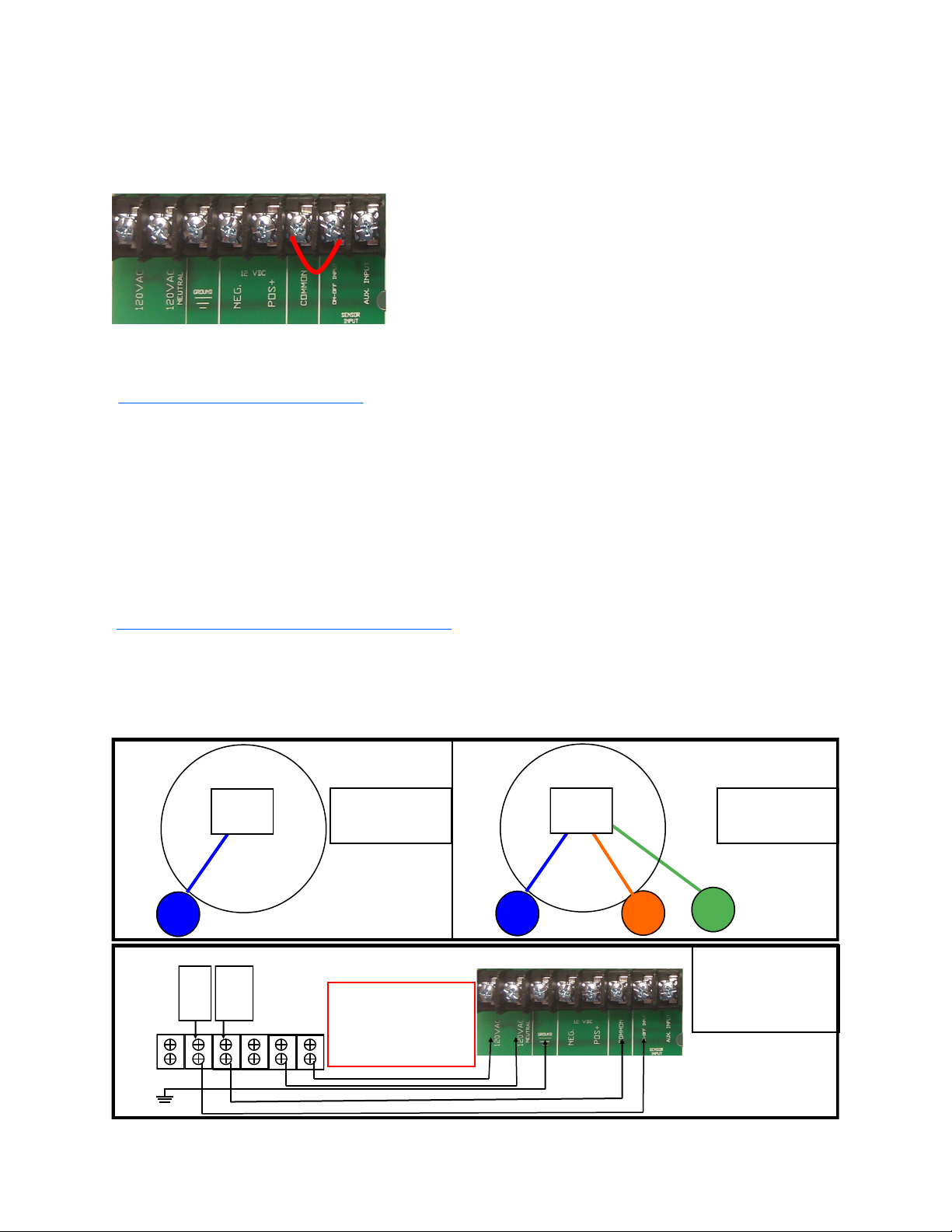
CAUTION: Never connect any voltage to the HOT SHOT SENSOR Input terminals. The Hot Shot sup-
plies the voltage needed for sensor switching (use dry relay contacts only). Make sure the pivot’s well kill
terminals do not have voltage from previously wired configurations.
ATTENTION: Depending upon the style of system that your are going to control with the Hot Shot
Wireless Controller you may need to supply additional parts. Such as relays, step-down transformers, Mur-
phy switches etc. These items are suggested in the wiring guides that follow in this manual.
HOW IT WORKS
Think of the HOT SHOT system as a control wire going from the transmitter site to the receiver site. When the
Hot Shot Transmitter’s SENSOR ON-OFF Input is connected to COM, a small delay timer is started. After the
delay timer has expired, the transmitter will send the (Relay ON) command to the receiver. This will close the
relay contacts between N.O. and COM. When the SENSOR ON-OFF input at the transmitter is opened it will send
the (Relay OFF) command to the receiver switching the relay back to N.C. connected to COM. Battery backup in
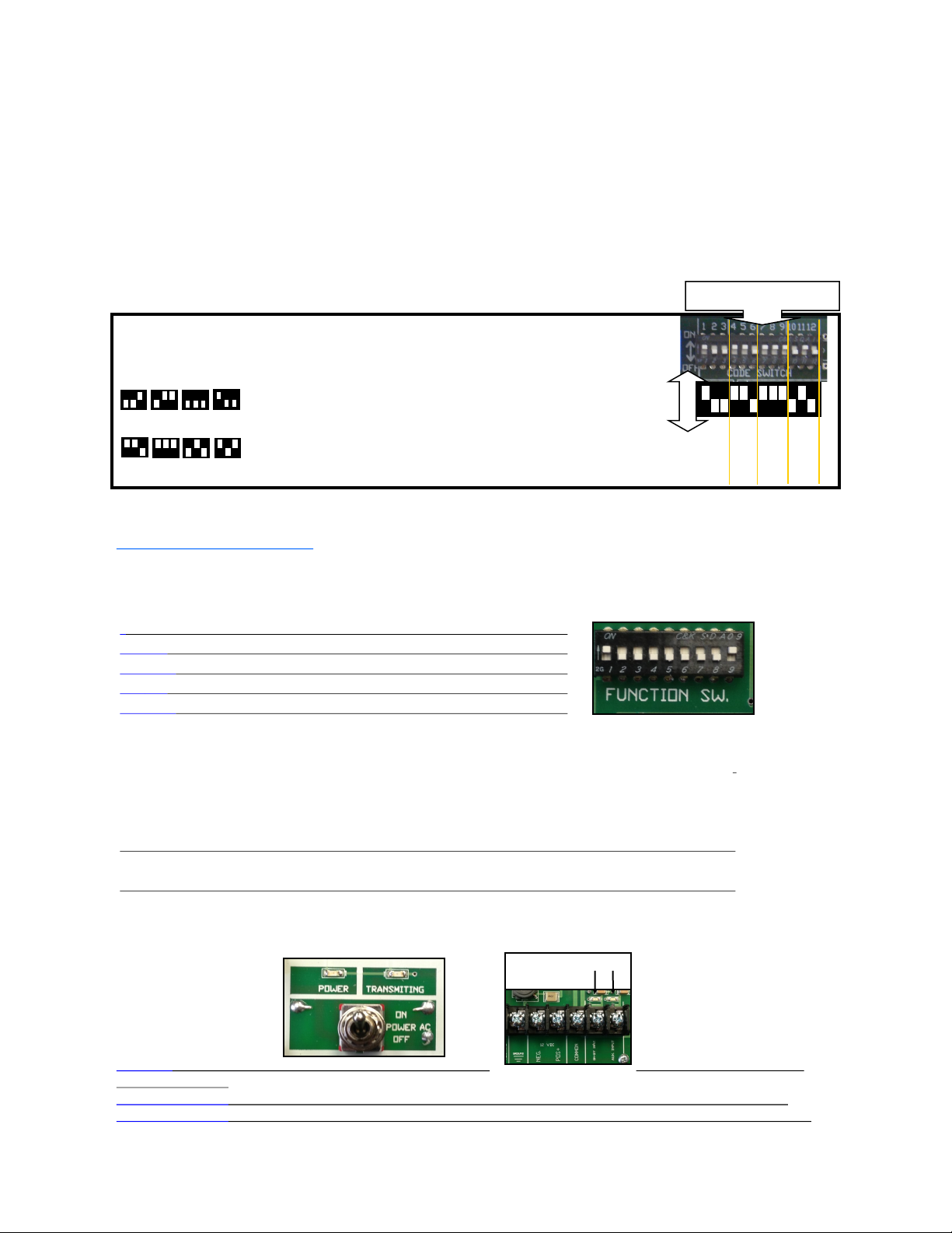
the transmitter will still allow the HOT SHOT to work in case of power outage. Each system is coded with its own
four digit code so it will not interfere with other systems in the same area. The following manual has been pre-
pared to provide details for Transmitter installation on electric and engine driven pivots.
MOUNTING
Cabinets are a weatherproof UV protected NEMA 4X cabinet with mounting ears on top and bottom. The trans-
mitter/receiver control box can be mounted on the side of a control panel, pole or any other surface as long as the
antenna does not have metal running within 12” of the antenna whip. If longer range is needed, an external long
range antenna can be used. Do not mount the HOT SHOT receiver to the well engine or cover because the strong
vibrations can be harmful to the unit.
If installing these on a Variable Frequency Drive pump do not mount the receiver unit to the VFD because of the
potentially strong magnetic field interference that can be produced by these drives. The further away it is mounted
the better it is for the Hot Shot Unit.
BATTERY BACKUP
During a power outage, a gel cell rechargeable battery supplies power to the transmitter for approximately 24
hours. This allows the transmitter to send a shutdown signal to the receivers when the pivot has lost power. The
Hot Shot Transmitter comes with a battery save feature that will turn off the Hot Shot Transmitter if the voltage
drops from 12vdc to 10vdc. This function will add years of life to the gel cell battery.
Important... When the battery has discharged, it will take approximately 2 to 3 hours for the battery to
charge enough to operate the transmitter in case of another power failure. The battery should be replaced
every year for the best reliability during power outages.
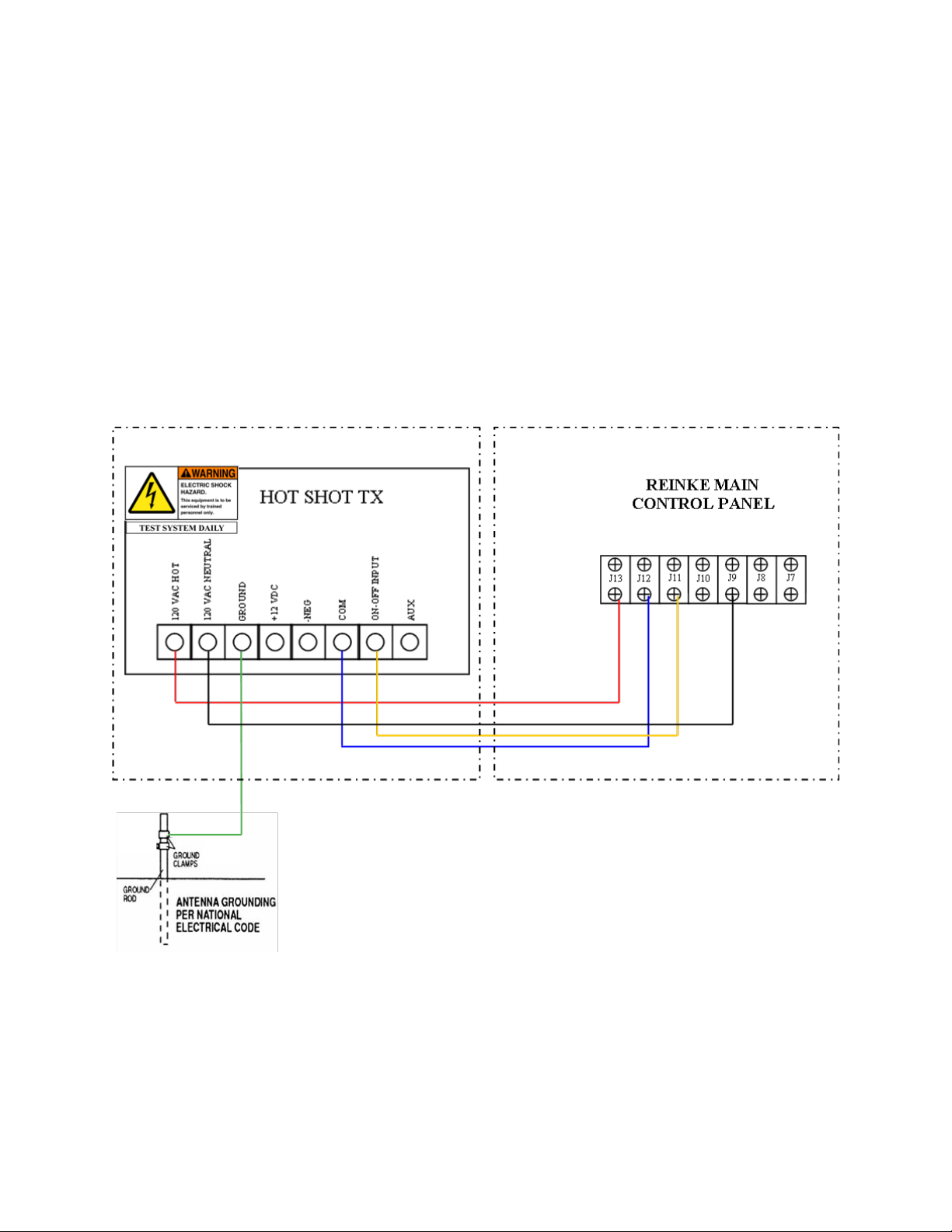
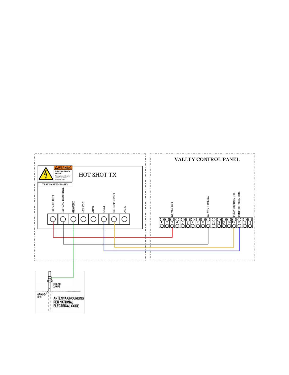
ATTENTION: All Hot Shot units have a designated GROUND Terminal. Hot Shot units must have
there ground terminal connected to a proper ground or grounding system as per the NEC (National Electri-
cal Code) and or your local and state electrical code guidelines.

3
CODE SWITCH SETTINGS
All transmitters and receivers will be shipped from the factory with preprogrammed 4 digit system codes. This
ensures that your neighbor will not duplicate the same system code as your units. Your transmitter and receiver
system codes should already match, so you do not need to program any codes. If a new secure system code is
needed for your installation please call 785-623-1500 to be issued a secure system code for your area that the
system will be operating in.
If you ever need to replace a unit due to servicing, the field code can be programmed to match the existing or
new add on units. FOLLOW THE EXAMPLE BELOW…
FOR CODE QUESTIONS? CALL 785-623-1500
89
7
EXAMPLE: CODE 6789
KEY
7
8
9
0
5
63
4
6
OFF ON
Use the # KEY to the left
to make each digit of the
code. It takes three of the
switches to make one num-
ber of the code.
Use switches 1,2,3 for the
first # in the code. Switches
4,5,6 for the second #.
Switches 7,8,9 for the third
#. Switches 10,11,12 for the
fourth #.
Code Switches
INDICATOR LEDS
POWER Indicates that the Transmitter has power and is ready to operate.
TRANSMITTINGIndicates when the Transmitter is transmitting.
SENSOR LEDS When these LED’s are on it indicates that the terminal below it is connected to the COMMON terminal.
SENSOR LEDS
TRANSMITTER FUNCTION SWITCH SETTINGS
SWITCH#
4ON MAKES TRANSMITTER A UNIT #2 TRANSMITTER
4&5 both ON MAKES TRANSMITTER A UNIT #3 TRANSMITTER
5ON MAKES TRANSMITTER A UNIT #4 TRANSMITTER
5&6 both ON MAKES TRANSMITTER A UNIT #5 TRANSMITTER
6ON MAKES TRANSMITTER A UNIT #6 TRANSMITTER
(see more about this feature on page 12)
8ON ACTIVATES THE TEST BEACON (Used for testing and range finding only. When activated the transmitter will
send a code every 10sec cycling the receivers relay. To activate this feature put a jumper wire from the ON-OFF INPUT to
COMMON on the relay input you want to test. DO NOT have the receiver wired to the pump during this test. This func-
tion must be turned off for normal operation. (More details on page 4)
OFF NORMAL OPERATION MODE
9ON REFRESH (This function will retransmit the state of the Sensor Inputs once every 45 minutes.)
OFF NO REFRESH (Transmits the code only when there is a change of state on the Sensor Inputs.)
To watch a “How To” video on this feature click on the link below:
“CODE SWITCH SETTINGS”

4
BASIC PIVOT PANEL INSTALLATION
Most pivot installations will use this method because they only have a single throw relay in their panel. (Single
throw relays only have a COM and NO contact.) In most installations Function Switches 1 thru 8 need to all be
turned OFF. The pivots well control relay will be connected to the ON-OFF INPUT and the COMMON input
on the transmitter. When there is contact made between ON-OFF INPUT and COMMON (when requesting
water) the transmitter will send out the ON code to the receiver. When contact is opened between ON-OFF
INPUT and COMMON (such as when the pivot is finished or stop water) the transmitter will send out the OFF
code. See the diagrams below. Brand specific instructions are shown later in the wiring diagrams.
OPERATING THE TEST BEACON
The Test Beacon function is turned on and off by using FUCNTION SWITCH #8 (see above). This feature is
used for testing and range finding purposes only. To activate the Test Beacon first turn OFF the power to the
transmitter. Turn function switch #8 on and connect a small jumper wire from the ON-OFF INPUT terminal to the
COMMON terminal and then turn the power back ON to the transmit-
ter. See diagram below. When turned ON the Transmitting LED will
blink and the code will be transmitted every 10 seconds cycling the
receiver’s relay. DO NOT have the receiver relay wired up to the
pump during this procedure because it will continually open the relay
for 10 seconds and then close the relay for 10 seconds causing damage
to the pump.
Function switch #8 must be turned OFF, the jumper wire removed
and then turn off the power on the transmitter power switch to
take it out of Beacon Mode.
Trans Terminal Strip
Shown in the diagrams below is a generic diagram of how to wire a pivot panel to the Hot Shot Transmitter.
This method is used for one pivot with one well or one pivot with multiple wells that will always operate at
the same time. It can also be used with multiple pivots sharing one well or multiple wells as long as only 1
pivot is operating at a time and the other transmitters are switched OFF. The wiring for each transmitter is
the same.
WELL
1
FIELD LAYOUT
EXAMPLE 2
Pivot A and all the
wells will be on the
same field code.
WELL
1
WELL
2
PIVOT
A
WELL
3
PIVOT
A
FIELD LAYOUT
EXAMPLE 1
Pivot A and the well
will be on the same
field code.
Transmitter Terminal Strip
120v
120v neutral
PIVOT PANEL TERMINAL STRIP
PUMP
CONTROL
NO
PUMP
CONTROL
COM
This is the basic way
to wire up the Hot
Shot transmitter to
most pivot panels.
WARNING
Make sure there is no
voltage on the pump
control contacts.
Earth
Ground
To watch a “How To” video on this feature click on the link below:
“OPERATING THE TEST BEACON”
To watch a video on this click on the link below:
“UNDERSTANDING THE 810-T TRANSMITTER”

5
REINKE PIVOTS
WIRING INSTRUCTIONS FOR BASIC OPERATION
Typically all functions switches are off unless advanced features are needed. See function
switch setting on page 3 for details.
To supply the 120vac needed for the Hot Shot Transmitter to operate, run a wire from
the pivot panel’s J13 terminal to the 120vac Hot terminal on the transmitter. Run another wire
from the pivot panel’s neutral terminal J9 to the 120vac neutral terminal on the transmitter.
Make sure the pivot’s well kill terminals DO NOT have any voltage from previously
wired configurations. Run a wire from terminal J12 to the Hot Shot Transmitter’s COM input
terminal. Run a wire from terminal J11 to the Hot Shot Transmitter’s ON-OFF INPUT termi-
nal. Connect a wire from the Lighting Ground terminal of the Hot Shot Transmitter to an NEC
approved earth ground rod. See diagram below.

6
VALLEY MODELS
4000, 6000, & PANELS WITH 3 SEC DELAY PCB.
WIRING INSTRUCTIONS FOR BASIC OPERATION
Typically all functions switches are off unless advanced features are needed. See function
switch setting on page 3 for details.
To supply the 120vac needed for the Hot Shot Transmitter to operate run a wire from
the pivot panels 120vac hot terminal on the fuse block to the 120vac Hot input on the transmit-
ter. Run another wire from the pivot panels neutral buss bar to the second 120vac Neutral input
on the transmitter.
With these models we recommend that you use terminal #3 and #4 on the 3 Sec Delay
PCB to control the Sensor on the Hot Shot Transmitter. Remove the wires that currently go in-
to them and cap them off. Run a wire from terminal #3 on the 3 Sec Delay PCB to the COM
input on the transmitter. Run a wire from terminal #4 on the 3 Sec Delay PCB to the ON-OFF
input on the transmitter. Connect a wire from the Lighting Ground terminal of the Hot Shot to
an NEC approved ground rod. See diagram below.

7
VALLEY MODELS
8000, PRO PANEL, SELECT PANEL & SIMILAR
WIRING INSTRUCTIONS FOR BASIC OPERATION
Typically all functions switches are off unless advanced features are needed. See function
switch setting on page 3 for details.
To supply the 120vac needed for the Hot Shot Transmitter to operate run a wire from
the pivot panels terminal #3(120vac Hot) to the 120vac Hot terminal on the transmitter. Run
another wire from the pivot panels terminal #9 or #10 (120vac Neutral) to the 120vac Neutral
terminal on the transmitter.
To connect the pivot panels well control relay to the Hot Shot Transmitter run a wire
from terminal #15 (PUMP CONTROL NO) to the transmitters ON-OFF input terminal. Now
run a wire from terminal #16 (PUMP CONTROL COM) to the transmitters COM input termi-
nal. Connect a wire from the Lighting Ground terminal of the Hot Shot to an NEC approved
ground rod. See diagram below.

8
T-L ELECTRIC PANEL (ALLEN BRADLEY)
WIRING INSTRUCTIONS FOR BASIC OPERATION
Typically all functions switches are off unless advanced features are needed. See function
switch setting on page 3 for details.
Attention: This install requires a 24vac to 120vac transformer and a 24vac relay.
To supply the 120vac needed for the Hot Shot Transmitter to operate, install a 24VAC
to 120VAC step up transformer. These are available to purchase from Hot Shot Systems. Run
two wires from the 24 VAC input on the transformer to terminal #9 and #11 in the T-L Allen
Bradley Panel. Then take the 2 wires from the 120VAC output side and run them to the trans-
mitters two 120vac inputs. INSTALL a 24vac relay “Interface Relay” to control the Sensor
input on the transmitter. Control the Interface Relay by running a wire from the Allen Bradley
panel’s terminal #1 and #2 to each side of the Interface Relays coil terminals. Run a wire to
connect the COM terminal on the 24vac Interface Relay to the COM input on the transmitter.
Wire up the NO terminal on the 24vac Interface Relay to the ON-OFF Input on the Transmitter.
Connect a wire from the Lighting Ground terminal of the Hot Shot to an NEC approved ground
rod. See diagram below.

9
ENGINE DRIVEN PIVOTS
WIRING INSTRUCTIONS FOR BASIC OPERATION
Typically all functions switches are off unless advanced features are needed. See function
switch setting on page 3 for details.
Attention: This install requires a 12vdc relay.
Run a wire from the B terminal on the engines Murphy switch to the +12vdc input on
the transmitter. Run a wire from the ground on the Murphy or from the NEG of the engines
battery to the NEG input on the transmitter. Now install a 12vdc Interface Relay to control the
SENSOR inputs on the transmitter. To control the 12vdc Interface Relay run a wire from the
engines Murphy switch terminal C on a 117 or from the terminal NC on a 518 to one side of the
relays coil terminals. Run another wire from the ground on the Murphy or from the NEG of the
Hot Shot Transmitter to the other coil terminal on the 12vdc Interface Relay. Now run a wire
from the 12vdc Interface Relay’s NO terminal to the ON-OFF INPUT on the transmitter. Run
another wire from the 12vdc Interface Relay’s COM terminal to the COM input on the transmit-
ter. Connect a wire from the Lighting Ground terminal of the Hot Shot to the ground lug of the
panel. See diagrams below.

10
ZIMMATIC PIVOT 10 WIRE SYSTEM
WIRING INSTRUCTIONS FOR BASIC OPERATION
Typically all functions switches are off unless advanced features are needed. See function
switch setting on page 3 for details.
Attention: This install requires a 24vac relay.
To supply the 120v needed for the Hot Shot Transmitter to operate run a wire from the
pivot panels 120v X1 terminal to the 120vac Hot terminal on the transmitter. Run another wire
from the 120v X2 terminal to the 120vac Neutral terminal on the transmitter. INSTALL a
24vac relay “Interface Relay” to control the Sensor input on the transmitter. Control the Inter-
face Relay by running a wire from one side of the relay coil to terminal #64 and connect the
other side of the relay coil to terminal #4. Wire the N.O. side of the Interface Relay to the ON-
OFF INPUT terminal on the transmitter. Wire the COM terminal of the Interface Relay to the
COM terminal on the transmitter. Connect a wire from the Lighting Ground terminal of the Hot
Shot to an NEC approved ground rod. See diagram below.

11
ZIMMATIC PIVOT 11 WIRE SYSTEM
WIRING INSTRUCTIONS FOR BASIC OPERATION
Typically all functions switches are off unless advanced features are needed. See function
switch setting on page 3 for details.
Attention: This install requires a 24vac relay.
To supply the 120v needed for the Hot Shot Transmitter to operate run a wire from the
pivot panels 120v X1 terminal to the 120vac Hot terminal on the transmitter. Run another wire
from the 120v X2 terminal to the 120vac Neutral terminal on the transmitter. INSTALL a
24vac relay “Interface Relay” to control the Sensor input on the transmitter. Control the Inter-
face Relay by running a wire from one side of the relay coil to terminal #64 and connect the
other side of the relay coil to terminal #65. Wire the N.O. side of the Interface Relay to the ON-
OFF INPUT terminal on the transmitter. Wire the COM terminal of the Interface Relay to the
COM terminal on the transmitter. Connect a wire from the Lighting Ground terminal of the Hot
Shot to an NEC approved ground rod. See diagram below.

12
NOTE: This equipment has been tested and found to comply with the limits for a Class B digital
device, pursuant to part 15 of the FCC Rules. These limits are designed to provide reasonable protection
against harmful interference in a residential installation. This equipment generates, uses and can radiate
radio frequency energy and, if not installed and used in accordance with the instructions, may cause harm-
ful interference to radio communications. However, there is no guarantee that interference will not occur in
a particular installation. If this equipment does cause harmful interference to radio or television reception,
which can be determined by turning the equipment off and on, the user is encouraged to try to correct the
interference by one or more of the following measures:
• Reorient or relocate the receiving antenna.
• Increase the separation between the equipment and receiver.
• Connect the equipment into an outlet on a circuit different from that to which the
• receiver is connected.
• Consult the dealer or an experienced radio/TV technician for help.
15.21 INFORMATION to USER:
The users manual or instruction manual for an intentional or unintentional radiator shall caution the user
that changes or modifications not expressly approved by the party responsible for compliance could void the
user’s authority to operate the equipment.
FCC License is not required. This device operates on frequencies authorized for use in the Multi-
Use Radio Service (MURS). MURS frequencies are available for unlicensed business or personal use. Any
changes or modifications may void the user’s authority granted by the FCC to operate this radio and should
not be made. Use of this radio outside the country where it was intended to be distributed is subject to gov-
ernment regulations and may be prohibited.
UNIT # - FUNCTION SWITCHES(4,5,6,)
Using unit #’s on the transmitters and receivers can create a more precision controlled system. When needing to
use multiple transmitters that control a single receiver, assigning unit #’s to each transmitter on the system will
help the receiver to differentiate between the transmitters controlling it. Like when operating a system capable
of running a Last Pivot Standing scenario. All 810-T transmitters come from the factory set in the default mode
as a #1 transmitter. Meaning they will only control the relay output #1 on a 810-R Plus receiver, a receiver set as
a Unit #1 receiver or channel 1 of a receiver operating in Last Pivot Standing mode. See receiver manual for
details on receiver Unit # Switch settings. Turning on function switch #4 will make a transmitter a Unit #2 trans-
mitter that will control the relay output #2 on a 810-R Plus receiver, a receiver set as a Unit #2 receiver or chan-
nel 2 of a receiver operating in Last Pivot Standing mode. The results are the same for each corresponding Unit
# that a transmitter is set to.
To watch a “How To” video on this feature click on the link below:
“Unit #s and Last Pivot Standing Mode ”
SWITCH#
4ON MAKES TRANSMITTER A UNIT #2 TRANSMITTER
4&5 both ON MAKES TRANSMITTER A UNIT #3 TRANSMITTER
5ON MAKES TRANSMITTER A UNIT #4 TRANSMITTER
5&6 both ON MAKES TRANSMITTER A UNIT #5 TRANSMITTER
6ON MAKES TRANSMITTER A UNIT #6 TRANSMITTER

13
HOT SHOT GROUNDING
FOR SAFETY AND PEAK PERFORMANCE
Hot Shot wireless systems are equipped with a GROUND terminal that
needs to be connected to an NEC approved ground rod. A Hot Shot has
various lightning and static protection devices incorporated on the cir-
cuit board that require proper grounding to operate. Any equipment or
device panels operating with or near the Hot Shot should also be con-
nected to the grounding system. A good ground will enhance the trans-
mit and receive range of the Hot Shot System.
GROUNDING
PER NATIONAL
ELECTRICAL CODE
DEVICE
PANEL
To watch a “How To” video on this feature click on the link below:
“PROPER GROUNDING”

14
Warranty
The warranty below constitutes the only warranty in connection with any sale from Hot Shot Systems Inc.
and is in lieu of all other warranties, express or implied, written or oral. THERE ARE NO IMPLIED
WARRANTIES OF MERCHANT-ABILITY OR FITNESS FOR A PARTICULAR PURPOSE THAT AP-
PLY TO ANY SALE FROM HOT SHOT SYSTEMS INC.
Hot Shot Systems Inc., warrants to You that Products (Products meaning any item purchased form Hot Shot Systems) will be free from defects
in materials and workmanship under normal use and service for one (1) year from the purchase date. A product issue under this Limited War-
ranty must be presented during the Limited Warranty period and within thirty (30) days after any covered condition has occurred. A claim un-
der this Limited Warranty shall be satisfied by either, in Hot Shot Systems sole discretion, repairing or replacing the Product. Replacement
Products may be new or reconditioned.
To make a claim under this Limited Warranty, Hot Shot Systems must first issue You a Returned Material Authorization (RMA) number. This
number can be obtained by calling Hot Shot Systems and a RMA number will be provided over the phone. A copy of the RMA number must be
included with any materials shipped to Hot Shot Systems . The entirety of Products must be sent back to Hot Shot Systems and properly pack-
aged to ensure against damage during shipping. If Hot Shot Systems determines that the claim is covered by this Limited Warranty, Hot Shot
Systems will either, in its sole discretion, repair or replace the Products and/or part. Any damages not covered under this Limited Warranty will
not be repaired until a purchase order is received.
The Limited Warranty period shall not be extended by the replacement or repair of Products or parts under this Limited Warranty but the re-
maining Limited Warranty period shall continue in effect and be applicable to the replaced or repaired Products or parts under conditions of the
Limited Warranty.
The term “Long Range Wireless Control” is not a guarantee of proper radio operation everywhere in all conditions. Radio operation is subject
to transmission and receive limitations, customer equipment, weather, topography and other environmental and electrical considerations associ-
ated with radio technology also affect radio operation and radio operation may vary significantly within buildings. The radio operation range of
Products is not guaranteed, and Hot Shot Systems cannot and does not guarantee or represent that the radio operation will operate correctly in
all conditions. It is Your responsibility to determine daily if radio operation is operating correctly and to monitor the Products to determine the
communication between Products. You should contact Hot Shot Systems for assistance if needed. As such, Hot Shot Systems is not liable for
any causes of action, pollution, incurred costs, losses of any kind or damages of any kind whatsoever arising out of mistakes, omissions, inter-
ruptions, errors, customer equipment or defects in the radio operation and or Products.
Intended Use. Products are intended for non pollutant, non hazardous and non critical use only. Products are to be used and installed per the
installation guide and any other instructions provided by Hot Shot Systems (collectively, the “Seller’s Guidelines”). Any use beyond the intend-
ed non pollutant, non-hazardous and non critical use or against the Seller’s Guidelines (“Unintended use”) are at the End-User’s own risk, and
Hot Shot Systems does not warrant or make any representations whatsoever regarding the use of Products for any unintended use. Hot Shot
Systems’ Products are convenience items and are not intended to be a substitute for normal maintenance, monitoring, control and proper upkeep
of equipment or property that Products are monitoring or controlling. Hot Shot Systems’ Products are convenience items and are not intended to
monitor equipment, control equipment, liquids, chemicals or other items which are pollutants, vital, hazardous, necessary, and/or have life-or-
death consequences. The End-User should take care to determine prior to use whether Products are suitable, adequate or safe for the use intend-
ed. Since individual applications are subject to great variation, Hot Shot Systems makes no representation or warranty as to suitability or fitness
of Products for any specific application.
Upon expiration of the Limited Warranty period, all liability of Hot Shot Systems shall be terminated. This Limited Warranty will also be ter-
minated immediate due to any of the following cases: failure to follow installation and operating instructions, misuse or "Unintended use",
alteration, abuse, accident or tampering, and repair by anyone other than Hot Shot Systems.
THIS LIMITED WARRANTY IS EXCLUSIVE AND EXPRESSLY IN LIEU OF ALL OTHER WARRANTIES, OBLIGATIONS OR LIA-
BILITIES, WHETHER WRITTEN, ORAL, EXPRESS OR IMPLIED, INCLUDING ANY WARRANTY OF MERCHANT-ABILITY OR
FITNESS FOR A PARTICULAR PURPOSE, OR OTHERWISE. IN NO CASE SHALL HOT SHOT SYSTEMS BE LIABLE TO ANYONE
FOR ANY CONSEQUENTIAL OR INCIDENTAL DAMAGES FOR BREACH OF THIS WARRANTY OR ANY OTHER WARRANTIES
WHATSOEVER. This Limited Warranty gives specific legal rights.
No employee, agent, dealer or other person is authorized to give any warranties on behalf of Hot Shot Systems Inc., nor to assume for it any
other liability in connection with any of its products, except an officer of Hot Shot Systems Inc., in a signed writing.
LIABILITY
Hot Shot Systems Inc. and its directors, officers, employees, subsidiaries and affiliates shall not be liable for pollution, pollution clean up, per-
sonal injury, property damage, hazardous conditions created, fluid spill cleanup, loss of product, loss of profit, or any other loss or expenses
based on a claim the product(s) failed to operate properly. Test product daily to see if any malfunctions are present. If using this product in a
situation where it is extremely critical to control your device to prevent damage of any kind, you must also use a call out system to notify a
person in control of this situation. If this warranty and statement of liability is unacceptable, then do not purchase these products.
Hot Shot Systems makes no representation that Products and Services will reduce any risk of property loss, product loss, loss of profit, pollution
or personal injury or prolong the life of any equipment or other property; or that Products and Services will in all cases provide adequate warn-
ing and protection. You understand that Products if properly installed and maintained may only reduce the risk of property loss or other loss but
Products and Services are not an insurance or a guarantee that there will be no property loss, product loss, loss of profit, pollution or personal
injury or other loss as a result. CONSEQUENTLY, HOT SHOT SYSTEMS SHALL HAVE NO LIABILITY FOR ANY POLLUTION,
PRODUCT LOSS, LOSS OF PROFIT, PROPERTY DAMAGE, PERSONAL INJURY OR OTHER LOSS OR EXPENSES INCURRED
BASED ON A CLAIM THE PRODUCTS AND SERVICES FAILED TO GIVE WARNING.
Table of contents