manuals.online logo
Brands
  1. Home
  2. •
  3. Brands
  4. •
  5. Hotech
  6. •
  7. Accessories
  8. •
  9. Hotech Advanced CT User manual

Hotech Advanced CT User manual

HOTECH
COOTION
9320 Santa Anita Ave. #100
Rancho Cucamonga, A 91730
U.S.A.
Tel: (909)987-8828, Fax: (909)987-8809
.hotechusa.com
NWCQ)II
INVOICE NO: 0621193
DATE: June 21, 2019
Bill To: Ship To:
James Yoder
SALES P.O. NUMBER SHIP DATE SHIPPED VIA F.0.B. POINT TERMS DUE DATE
HT 104097 06/21/19 UPSG Ranc o C., CA Paypal
Paid
QUANTITY DESCRIPTION UNIT PRICE AMOUNT
1 HLC-925: HyperStar Laser Collimator for 9. 5"
&
11" $530.00 $530.00
Hypersar telescope, includes a fine adjustment stage.
S/N: 7998
1 HTGL-G3: Astro Aimer G3. Green laser with flashlight. $119.95 $119.95
S/N: G08758
-
-
---
----
-- -
-------
------
--
1 -Clip: Astro Aimer Belt Clip. $15.00 $15.00
1 V-Mount-01: Astro Aimer V-Mount. $15.00 $15.00
1 VMT-RB: V-Mount Rail Base $12.00 $1 .00
SUBTOTAL
SALES T
SHIPPING
&
HANDLING
TOTAL
$691.95
n/a
$15.95
$707.90
THANK YOU FOR YOUR BUSINESS
Instruction Sheet
ADVANCED CT LASER COLLIMATOR for CASSEGRAIN T LESCOPES
Thank you for purchasing the state-of-the-a H TECH
Advanced CT Laser Collimator instrument. This instrument
uses the most advanced laser and optical technology to
enable the user to achieve excellent collimation in a ve
sho distance. Collimation is the process of aligning a
telescope's optics. The laser collimator makes the
collimation process more eicient and can increase
collimation accuracy. Your telescope is aligned at the
factory, but harsh handling during shipping can cause
misalignment. Some telescopes are not well collimated
when shipped. Misaligned collimation can mean lessened of
optical efficiency and result in poor image contrast,
astigmatism, and blurry images. The following describes
how to collimate your Cassegrain style telescope with the
aid of the Advanced CT Laser Collimator.
Please read the entire instruction sheet before using your Advanced CT L ser Collimator
Be aware of the following as you use your Laser Collimator:
Only turn ON your laser(s) when you are going to use it. The laser should only be used with adult supeision, and should only
be used for collimating a telescope. Never point the laser or the reflection of the laser collimator at anyone's eyes. These
instructions cover collimation of Schmidt Cassegrain telescopes, but most Cassegrain type instruments are collimated in similar
fashion. For telescopes with both adjustable secondary and primary mirror (e.g. Ritchey-Chretien type telescope), please email
or call us for details. All lasers on the collimator are class II (
<1
mW). For additional information, please visit our website,
www.hotechusa.com, or write us at info@hotechusa.com.
Collim tion Basics You Must Know Before Sta
What to Adjust:
The only user accessible collimation adjustment on a Schmidt Cassegrain Telescope is the seconda mirror via three screws.
Therefore, you only need to adjust the three alignment screws located at the front of the telescope behind the secondary mirror
(see illustration below). For ease of manual adjustment, we recommend replacing the stock alignment screws with knob headed
screws (available from several vendors) to allow easier, finer adjustment.
Collitor
Lar 1
cal s
r
3
r
2
r
1
return
FIG.1
conda rror Pri rror
Mirror
How the Collimator Works:
The Advanced CT Laser Collimator samples the entire optical system (primary, seconda mirror, and the eyepiece axial
position) with a si
m
u
l
ated la
r
ge a
p
eure flat-wavefront light source generated by three parallel lasers positioned behind the
ta
rg
et p
l
ate
.
T
h
e ta
r
ge
t p
late provides a clear view of the optics
'
alignment condition when the three lasers are reflected back on
t
he
targ
et
(FIG. 1 ). I
t is e
x
tremely critical that the lasers are pointed s
q
uare-on
(
co-aligned
)
to the primary mirror for an accurate
r
e
ad
i
ng. I
t is
u
st li
k
e looking at a distant star and centering the star in th
e
ey
e
piece field of
v
iew during a star test, except the
star is only a
b
out
3
feet in fro
n
t of the telesco
p
e
.
Advanced CT Laser Collimator User's Manual (vB), pa e 1 of
7
To ensure accurate aiming, you use the d ffused crosshair projected from the center of the collimator as a guide to optically
center aim the prima mirror back to the center of the collimator (FIG. 2A), and center aim the return crosshair reflected from
the prima mirror to square up the collimator aiming (FIG. 28). Please expect to spend most time on these aiming adjustments.
Be patient and careful; the results will be well woh the trouble!
How to Adjust Collimation on Your Scope:
You can collimate your telescope at almost any position (e.g. telescope 20 deg. up) as long as
both the collimator and the telescope point square at each other. Once the lasers and
telescope are co-aligned, adjust the telescope's three secondary alignment screws carefully by
small amounts to move the three projected laser dots to the same bull's eye circle on the
collimator's target.
Process Flow ha:
1 . Set collimator distance
2. Install reflector in the telescope's visual back (2-inch or 1.25-inch as appropriate).
3. Aim telescope at the collimator (FIG. 2A)
4. Aim collimator at the telescope (FIG. 28)
5. Adjust secondary to move the three laser spots onto the same circle on the target.
Package Content:
1 x Premium Soft Caring Case
1
x
Advanced
CT L
aser Collimator
1
x
SC
A
R
eflector
M
irror (
1
.
2
5
"
or
2"
)
1
x
3V, CR1
2
3 L
ithium
B
a

e

1 x U
sers
M
anual (in co
v
er po
c
ket)
Advanced CT Laser Collimator User's Manual (vB), p ge 2 of
7
1.0. Settin the Laser Collimator on the Tri od
1.1. Where to setu the telesco e and the collimator
Position both collim tor and the telescope on solid ground (no carpeted, wooden floor, or other suace that will flex or vibrate).
Both telesco e and collimator must be on the s me round floor.
1.2. Setu the collimator on the tri od
). Aach the fine-adjuster to your tripod using the tripod's 1/4-20 bolt.
b). A ch the laser collim tor to the recommended fine adjustment stage
using the thre ded knob on the fine-adjuster and the -20 screw hole
on the boom of the collimator.
c). Lock the collimator firmly in place with the lock-knob on the fine
adjuster's 1 /4-20 bolt.
2. . Gettin Familiar with the HOTECH Advance CT Collimator
2.2. Switchin the laser to the ro er mode
Unthread the baery compament cap and inse the included CR123 lithium bae with the
positive side up (tip side up) and replace the b tte cap.
BL:
B cklight ON.
CL:
Three alignment l sers and b cklight ON.
rocedure for best result.
Other modes:
DT:
Three alignment lasers ON.
1 L:
Crosshair laser and backlight ON.
Please use the recommended mode in e ch
Position the collimator on a tripod bout 4 feet from a white wall with the t rget side facing the
wall. Rotate the rot ry knob on the top right corner of the collimator to activate different laser
modes. You will see the projected laser paerns on the w ll t v rious positions.
Mode 0:
Unit off.
Mode 1 :
Cross h ir l ser ON.
Mode 2:
Crosshair laser and three alignment lasers ON.
Mode
3: Crosshair laser, three alignment lasers, nd t rget backlight ON for night use.
2.3. Rou h adiustment
Switch the laser to Mode 2, lift the tripod and move the collim tor with the tripod to v rious
distances from the wall to see how the crosshair exp nds and contracts in size t different
dist nces.
2.4. Fine adiustent sta e adiustment
Place the tripod with collimator b ck on the ground. Adjust the fine- djustment stage s follows:
Veical Adjustment:
-
Th
e
larg
e
knob on
r
ig
ht
i
s for ro
u
gh ad
j
ustment in the veical direction.
L
oosen the l rge knob
a
nd le
v
el the laser before conti
n
uing.
- Th
e
foar
d
small k
no
b
is for
ine adjustment in the ve

ic l (up
/
down
)
direction. The large knob
must be lo
c
k
ed i
n
order to make to use this fine djustment.
Horizontal Adjustment:
- Th
e
l
e
ft side smal
l
kno
b is for fine adjustment in the horizont
l
(lef

right
)
direct
i
on.
Advanced CT Laser Collimator User's Manual (vB), p ge 3 of
7
the Reflector Mirror:
If the telescope is to be used mostly for visu l obseation, it's a good idea to collimate with your star
diagonal in place. Ple se note th t a poor quality diagonal, one with a misadjusted mirror, may
cause collimation problems. However, if photography or CCD imaging is planned, it is best to inse
the SCT mirror directly into the telescope's visual back. You will first, of course, need to thread your
visual b ck onto the telescope's rear po. Use either a 1 .25-inch or 2-inch visual back depending on
the size of the nose piece mirror you purchased.
4.0. Positionin the Laser Colli ator at the Pro er Distance
a). Position the collimator one tube length's distance in front of the telescope with
the target display facing the telescope (photo above).
b). Switch the collimator to Mode 1 (crosshair laser only).
c). Roughly aim the crosshair toward the telescope.
d). Experiment with the proper distance by lifting the tripod and collimator and
moving the collimator slowly toward and away from the telescope while keeping
the reflected crosshair on the target plate. Don't wor about getting the
crosshair peectly centered on the target at this point. You will see how the
crosshair contract and expands in size on the target plate in relation to the
distance adjustments.
e). Move the collimator to the distance where the crosshair is its smallest. This is
the back focal point of the prima mirror. Now, begin to move the target
towards the telescope until the crosshair exp nds to the size of the first ring.
f). Firmly position the tripod at this distance. This will be your collimating distance.
e
The distance between the laser collimator and your
telescope varies depending on the diameter and focal length
of your telescope. In general, the greater the distance from
the telescope, the higher ccuracy you will achieve. In
practice, any dist nce beyond the focal distance will be
suicient. In this procedure, we will identify the best
collimating distance for the telescope .


5.0. Achievin
This is the critical stage where you must co-align the collimator and your telescope for an accurate reading of your optics
alignment. DO NOT use the center of the seconda mirror assembly as a crosshair centering reference since the secondary
mirror might not be peectly centered on the corrector plate. Referencing the center of the secondary as the pointing axis does
not mean the rima is also on the axis. You can use it as a uick ross aimin , but not for final aimin adlustent.
Usin
g
a single-point light source emi

ing from the center of the collimator, the telescope can optically reference the reflected
li
g
ht and aim back to the source. The primary mirror reflects a filled cone-shaped beam and projects onto the collimator
'
s
target plate as a donut shape beam (seconda mirror shadow in the center
)
. Reference your ad
j
ustment only on the outer
d
i
ameter of the donut light beam to an e
q
ual-sized printed ring on the target. This techni
q
ue will optically center aim the
telescope to the collimator.
a
).
Place the provided diffuser (ma

e-finish tape) in front of the center crossh ir l
a
ser to diffuse
t
he l ser
.
b
)
.
U
se the telescope
'
s fine ad
j
ustment knob or its hand control to center im the donut light beam to an equ l or similar-sized
ring on the target
.
c
). Li
ne u
p
o
n
e a
xi
s at a t
im
e
,
up
/
down or lef

right, unless yo
u
are very
f
amili r
w
ith your telescope iming control.
F
or example, mo
v
e the telescope up
down ad
j
ustment to see where the donut light beam moves
,
and try to make
j
ust t
h
e
top and bo

om of the donut have the equal distance to one of the ring on the target.
Then
a
djust lef

ri
g
ht controls of the telescope to see where the donut light beam moves, and try to make just the left and
right side of the donut have the equal distance to the s me ring on the target.
d . Iterate ste c to close in the don
u
t on the s me rin .
Advanced CT Laser Collimator User's Manual (v ), page 4 of
7
SCTOTA
FIG.
Note: If the diffused light is too dim to see, you m y remove the diffuser and use the outer
edge of the crossh ir line as the s me referencing technique s the donut outer rim to line
up with the equal-sized ring on the t rget. Ignore the position of the crossh ir line to the
printed target cross in this step.
For example, when centering the lefright position of the horizontal outer edge l ser line,
ignore the veical crossh ir line offset position to the veical printed line on the target pl te.
Only t to bring the left nd right outer edge of the projecting horizont l laser line to equal
distance on the ring during this t sk. See photo illustration.
5.2. Aim collimator s uare to the telesco e
After the telescope is initi lly center imed t the collimator in step 5.1, the collim tor will also requires to pointing b ck at the
same origin to complete the co- lignment. In this step, you will djust the iming of the collim tor by referencing the projecting
crosshair to the printed cross on the target.
a). Remove the diffuser to see the projecting crosshair.
b). Use the
fine
adjustment knob on the fine adjustment st ge to refine the collim tor iming to line up with the printed cross
on the target pl te.
c). Again, line up one axis at time. St  with up/down djustment, then lefright adjustment.
d . Place the diffuser back on the center laser to see if the donut Ii ht be m is still centered. If not, re
Advanced CT Laser Collimator User's Manual (v8), p ge 5 of
7
5.3. Co-alignment confirmation
Continu to repeat the procedures in step 5, adjusting telescope and collimator until the donut and the crosshair are all
centered on the printed target. When you achi v this, it means both the telescope and the collimator are pointing square at
each other; for all intents and purposes, it's as if the t l scop were pointed at a distant star. Lock your telescope and you are
ready to diagnose your optics.
t
th
c
Ir
It
f
R
t R d th o·
60 H
.
ow
0
ea
e
raqnos re
esu on e o
ra
or
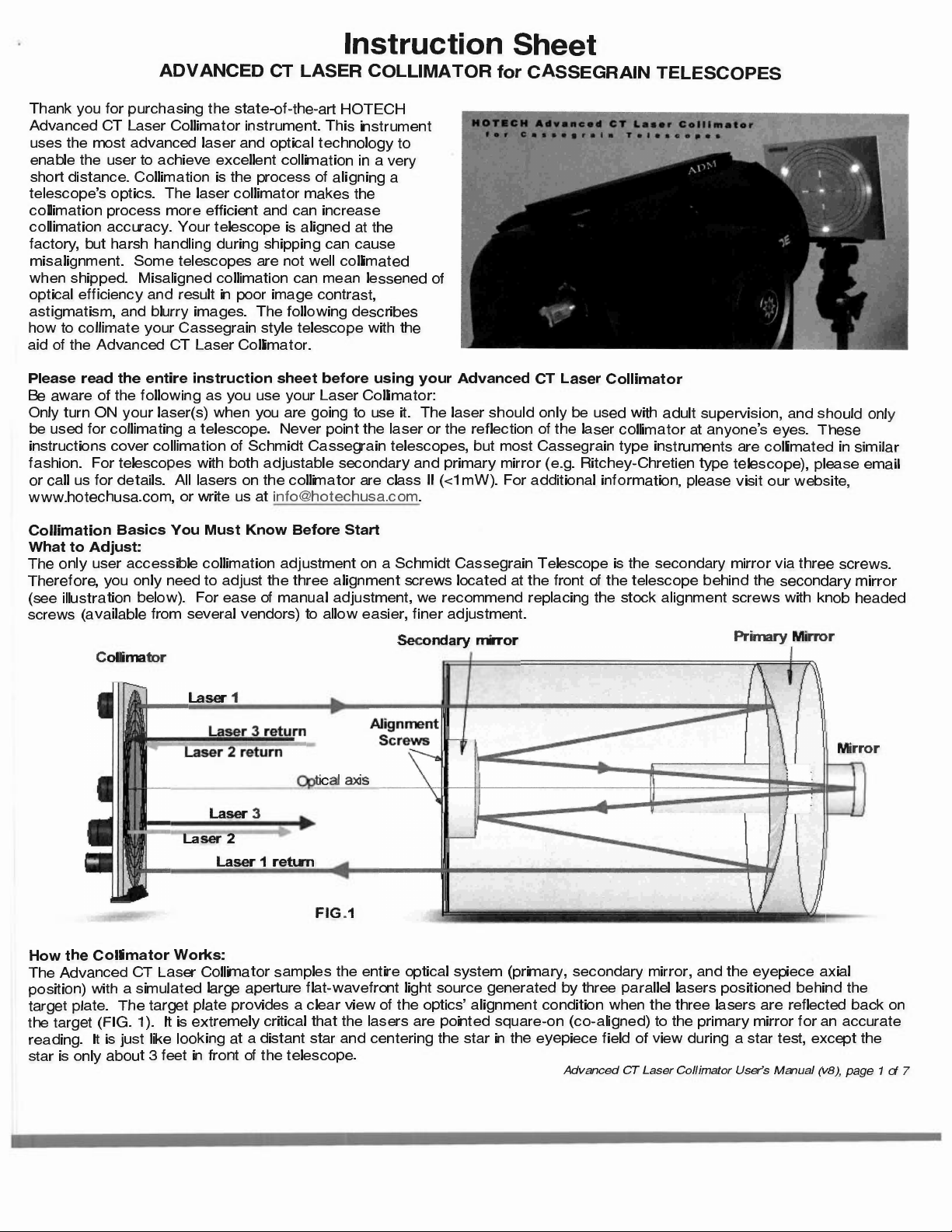
With the telescope and collimator properly positioned in St p 5, the collimator can accurately reveal collimation errors in the
tel scop 's optical system by m ans of the center deviation of thr e r turning laser dots on the target plate.
6.1. Locate the three laser dots
a). Switch to Mode 2 or Mode 3 (three lasers and the crosshair, or Mode 3 with backlight).
b). V rify that th crosshair is still cent r-pointed on both the target plate and the Alignment Tabs (or internal screws in the
case of a Meade scope).
c). Note the three laser dots on the target plate.
d). If the three laser dots are visible on the target plate, go to step 8 to collimate the telescope.
). If th thr laser dots are not visibl or ar only paially visibl on the target plate, please continue 6.2 and/or 6.3.
6.2. The SCA Reflector is not properly adapted
a). The SCA R fl ctor reflects the axial alignment of your visual back (or focuser draube with some types of telescopes).
You must install the SCA Reflector correctly (square in the visual back or drawtube). This axial position of the visual back
or draube affects the alignment of the entire optical system (telescope). Please refer to step 3 for proper SCA Reflector
installation.
b). If you have verified the SCA mirror is correctly installed, but the three laser spots are still completely or paially invisible,
continue to the next step, otheise go to step 7.
6.3. The SCA Reflector is not positioned at the focal because the scope's focus is out of normal visual range
a). This can happen if the telescop was last focused with a diagonal in place (and it is not installed now), or a focal reducer
was in the optical train the last tim the telescop was focused. The focal plane is too far out, and is not at the normal
visual position it would be in if the t lescope w re focused without a diagonal or focal reduce . If you do not want to use
the diagonal during CT collimation, you will need to adjust the telescope's focus. Continue to step b).
b). Adjust the focus to bring at least two laser dots into the full view on the target plate. Adjust the focus in one direction first
to see if any of the laser dots are moving toward the center direction of the target. If the laser(s) is moving or expanding
away from the center of the target, reverse the focusing direction to bring at least two laser dots into the full view of the
target plate. Go to step 7 to collimate your telescope.
6.4. Your telescope is grossly out of alignment
When your telescope is grossly out of alignment, the laser dots may be completely out of the target screen. If you believe this
to be the case, begin the collimation process anay and se if you can bring the three laser dots into the target screen. An
excellent check for a grossly miscollimat d scop is obs

ing the refl ctions of th telescope mirrors by looking directly down
the tube.
Y
ou will have to move the scope in a
z
imuth to do so, of course. Turn off the laser before proceeding. Proceed to step
7.
0
.
7 O Collimatmg the Telescope
The ob
j
ective of this step is to brin
g
the three laser dots onto the same ring on the CT collimator's target. You will need to
constantly check telescope and collimator positioning during the ad
j
ustmen
t
process to make sure proper aiming is maintaine
d
.
H
er
e
are few simple precautions to follow while ad
j
usting the seconda

mirror collimation ad
j
ustment screws located on the
secondary mirror assembly.
a.
N
e
v
er touch the central screw which holds the seconda

mirror (usually only older
S
CTs will
h
ave this central screw).
b. T
h
e three screws must be turned in by very small amo
u
nts.
N
o scr w b ing over-tight ned or
t
otally unscrew d. ALWAY
S
colli
m
ate by tightening screws
ON
LY
. O
nly when a screw is snug should you loosen the opposi
t
e screw(s
)
to continue
mo
v
ing the original screw in the proper direction. If collimation screws ar loose, collimation will not b maintained for long
!
c. As
y
ou ad
j
ust the collimation screws, obse

e the laser spot positions on the collimator to determine which screw(s) to turn,
and
by
how much.
7 .
. Collimate
y
our telesco
pe
a)
. Ad
j
ust the a
l
ignment screws to bring the three reflected laser dots onto the same ring on th target.
).
I
f you cannot br
i
ng a
ll
t
hr
ee
l
aser dots onto the target same target ring becaus the dots ar t
o
o far apa

,
adjust
th foc
u
s
to
m
er
g
e the three laser dots closer together.
c
)
. Check for proper aiming of the collimator and the telescope in step
5
.
T
he telescope mig
h
t shift in position if you apply too much pressure during seconda

mirror a
d
justment.
Y
ou must doubl
check whether you have nud
g
ed the telescope pointing out of co-alignment.
d)
. Iterate step
7
.
1
until both the three laser dots are on the same track on the targ t and the coll
i
mator and telescop are still
co-aligned.
Advanced CT Laser Cof/imator User's Manual (vB) page 6 of
7
8.0. Verifying and Fine Tuning Collimation
9.1. Star test to verify the adjustment
a). On your fir t obseing es ion, tar te t the tele cope to verify the adju tments.
The Advanced CT La er Collimator hould bring excellent collimation to your tele cope. Minor adjustment might be
required due to temperature variation during a long obseing e ion.
b). Choose a medium bright tar--Polaris i good in the Nohern Hemi phere. Defocu the scope a lile, just until diffraction
rings are seen. The tar hould look like a lile bull' eye.
Carefully center the tar and ob ee the diffraction ring . If they are concentric, collimation i good. If they are "squashed"
on one side, collimation require fuher adju tment.
9.0. Pos ible Scenarios where the Laser Collimation Does Not A ree with Star Collimation
It is pos ible that during collimation ( tep 7), the co-alignment of the collimator and the tele cope wa lightly off causing an
incorrect diagnosis. It i very critical to en ure both the collimator and the tele cope are co-aligned.
Do not adjust the collimation screw . Go to tep 5 to verify the co-alignment of the collimator and the tele cope and check if
three laser dot still fall on the same track. If both condition are met, your optical y tem i in good condition meaning they're
all lined u well on the ame o tical axi . If not, continue to the next te .
Due to machining tolerance on the prima mirror and improper grea ing on the baffle, ome tele copes exhibit more mirror
flop then others. A slight loo e tolerance will cau e major axial alignment deviation. The Advanced CT La er Collimator is
sensitive enough to pick up any deviation in tep 5. Prior to adju ting the econda alignment crew , ob ee the hifting
position of the three laser dots on the target by making two full turn clockwi e of the focu knob, then rever e half turn. The
shifting of the laser dots during the rever e turn tell how much focu hift is pre ent in the tele cope.
If the displacement is more than 2 track di tance, we recommend a rear cell Craord focu er to the tele cope (these are
available from man sources for focu in adiustment, leavin the built-in focu mechani m untouched.
We recommend replacing a poor visual back with a higher quality model (2-inch back are generally beer in quality than the
1.25-inch models furnished with SCT ). If the tele cope u e a rear-cell focu er, it' po ible to replace a poorly aligned one
w
ith ne
w
hi
g
her
gr
ade eyepiece drawtube or a focu er that ha tip
/
tilt adju tment to correct the axial error
. F
or example, a
M
oo
nli
te
CS
model
,
o
r
special modified focu er available from our web ite. Plea
s
e email or call u for availability.
Advanced CT Laser Collimator User's Manual (vB) page
7
of
7
Instruction Sheet
HYPERSTAR LASER COLLIMATOR for HYPERSTAR TELES OPES
Thank you for purchasing the state-of-the-a
patented HOTECH HyperStar Laser Collimator
instrument. This instrument uses the most advanced
laser and optical technology to enable the user to
achieve excellent collimation in a very sho
distance. Collimation is the process of aligning a
telescope's optics. The laser collimator makes the
collimation process more eicient and can increase
collimation accuracy. Your telescope is aligned at
the facto, but harsh handling during shipping can
cause misalignment. Some telescopes are not well
collimated when shipped. Misaligned collimation
can mean lessened of optical efficiency and result in
poor image contrast, astigmatism, and blurry images. The following describes how to collimate your Hyperstar telescope with
the aid of the HyperStar Laser Collimator.
Please read the entire instruction sheet before using your HyperStar Las r Collimator
Be aware of the following as you use your Laser Collimator:
Only turn ON your laser(s) when you are going to use it. The laser should only be used with adult supeision, and should only
be used for collimating a telescope. Never point the laser or the reflection of the laser collimator at anyone's eyes. These
instructions cover collimation of prime focus telescopes namely the Hyperstar configured telescope. All lasers on the collimator
are class II (<1 mW). For additional information, please visit our website, www.hotechusa.com, or write us at
i[email protected].
Collimation Basics You Must Know Before Sta
What to Adjust:
The accessible collimation adjustment on a Hyperstar is the tilt adjustment. On some telescopes (e.g. Celestron EdgeHD) has
additional adjustment on the center positioning of the corrector plate which helps in centering the Hyperstar assembly to fu her
refine and coincide to the prima mirror axis.
HOTECH
HyperStar Laser llimator
How the Collimator Works:
The HyperStar Laser Collimator samples the entire optical system (the prima mirror, the Hyperstar assembly, and the focal
plane) by simulating a large apeure flat-wavefront light source generated by three parall
e
l lasers positioned behind the tar
g
et
p
l
at
e
. Th
e t
arg
et p
l
ate
p
ro
vi
des a clear view of the optical ali
g
nment status in real time when the three lasers are reflected back
on th
e t
arg
et
. T
his
p
atented techni
q
ue of parallel laser beams allows near field collimation (one tube length in front of the
t
ele
sco
pe
)
a
t f
ar
ield
(i
nfinity
)
se

ing. The center crosshair laser helps you s
q
uaring u
p
th
e
collimator to the telescope optical
axis fr
o
m
t
h
e
di
re
c
t re
fl
e
c
ti
o
n
b
ack to the collimator target.
I
t is e
x
tremely critical that the lasers are pointed s
q
uare-on
(
co

al
ign
ed
)
t
o
the te
l
escope for an accurate reading and ad
j
ustment.
HyperStar Laser Collimator User's Manual (Vt), pa e 1 of 6
Collimation Angle:
You can collimate your telescope at alm st any position (e.g. telescope 10 degrees up) as
long as both the collimator and the telescope point square at each other.
Process Flow Cha:
1. Set collimator distance from the telescope.
2. Install Hyperstar reflector mirror at the sensor location with the proper adapter.
3. Co-align the collimator to the telescope optical axis.
4. Adjust Hyperstar assembly tilt.
5. Adjust Hyperstar assembly centering (if adjustment is available).
Pa kage Content:
1 x Advanced CT Laser Collimator
1 x HyperStar reflector mirror adapter
1 x High accuracy dual-sided reflector mirror
with detachable target cap
1 x Fine Adjustment Stage
1 x CR123 3V baery
1 x Premium caring case with manual
1 .1 . Where to setu the telesco e and the collimator
Position both collimator and the telescope on solid ground (no carpeted, wooden floor, or other suace that will flex or vibrate).
Both telesco e and collimator must be on the same round floor.
1 .2. Setu the collimator on the tri od
a). Aach the fine-adjuster to your tripod using the tripod's 1/4-20 bolt.
b). Aach the laser collimator to the recommended fine adjustment stage
using the threaded knob on the fine-adjuster and the -20 screw hole
on the boom of the collimator.
c). Lock the collimator firmly in place with the lock-knob on the fine
adjuster's 1 /4-20 bolt.
HyperStar Laser Collimator User's Manual (V1 ), pa e 2 of 6
2.0. Gettin Familiar with the HOTECH Advance T Collimator
Unthread the baery compament cap and inse the included CR 12 lithium baery with the
positive side up (tip side up) and replace the batte cap.
2.2. Switchin the laser to the ro er mode
Position the collimator on a tripod about 4 feet from a white wall with the target side facing the
wall. Rotate the rotary knob on the top right corner of the collimator to activate different laser
modes. You will see the projected laser paerns on the wall at various positions.
Mode 0:
Unit off.
Mode 1:
Crosshair laser ON.
Mode 2:
Crosshair laser and three alignment lasers ON.
Mode
3: Crosshair laser, three ali nment lasers, and tar ht ON for ni ht use.
Other modes:
DT:
Three alignment lasers ON.
BL:
Backlight ON.
1 L:
Crosshair laser and backlight ON.
CL:
Three alignment lasers and backlight ON.
Please use the recommended mode in each rocedure for best result.
2.3. Rou h adiustment
Switch the laser to Mode 2, lift the tripod and move the collimator with the tripod to various
distances from the wall to see how the crosshair expands and contracts in size at different
distances.
2.4. Fine adlustent sta e adiustent
Place the tripod with collimator back on the ground. Adjust the fine-adjustment stage as follows:
Veical Adjustment:
- The large knob on right is for rough adjustment in the veical direction. Loosen the large knob
and level the laser before continuing.
- The foard small knob is for fine adjustment in the veical (up/down) direction. The large knob
must be locked in order to make to use this fine adjustment.
Horizontal Adjustment:
- The left side small knob is for fine adjustment in the horizontal (lefright) direction.
erStar Reflector Mirror Assembl :
er Star
The dual-sided reflector mirror consists of three pas, the adapter ring, the reflector mirror, and the
target cap.
a). Thread the reflector mirror to the 8", 9.25/11", or 14" adapter ring that comes in a separate box.
b). Detach the camersensor from the HyperStar.
c). Remove the camera aachment ring.
d . Thread the reflector mirror assembl onto the H erStar.
4.0. Positionin the Laser Collimator at the Pro er Distance
The distance between the laser collimator and your
telescope varies depending on the diameter and focal length
of your telescope. In general, the greater the distance from
the telescope, the higher accuracy you will achieve. In
practice, any distance beyond the focal distance will be
suicient.
I
n this procedure, we will identif
y
the bes
t
collimating distance for the telescope.
HyperStar Laser Collimator User's Manual (Vt), pa e 3 of 6
a). Position the collimator one tube length's distance in front of t e telescope wit
t e target display facing t e telescope (p oto above).
b). Switc t e collimator to Mode 1 (cross air laser only).
c). Roug ly aim t e crosshair toward the telescope.
d). Experiment wit t e proper distance by lifting the tripod wit the collimator and
move the collimator slowly toward and away from the telescope while keeping
the reflected cross air on t e target plate. Don't wor about getting the
cross air peectly centered on t e target at t is point. In this step, you'll feel
how the crosshair contract and expands in size on the target plate in relation
between t e scope and t e collimator.
e). Move the collimator to t e distance w ere the crosshair is its smallest. This is
the back focal point of t e prima mirror. Now, move the target away from t e
telescope until t e cross air expands to the ring 6.5.
f). Firmly position the tripod at this distance. This will be your collimating distance.
5.0. Achievin
e
T is is the critical stage w ere you must co-align t e collimator and your telescope on the same axis for an accurate reading of
your optical alignment. DO NOT solely rely on centering the cross air laser on the HyperStar reflector mirror target as the
aiming reference since the Hyperstar assembly may be grossly tilted or not positioned in coincident with the telescope optical
axis in t e initial co-ali nment sta e.
Using the laser diffuser, t e primary mirror reflects the diffused laser back to t e collimator target. When t e donut shaped
reflection is center positioned on the collimator target plate, t e telescope is very close to be on t e same optical axis of t e
collimator laser. If t e donut edge is too coarse, you may also reference on the outer tip of the cross air to be on the same
ring.
a). Stick t e provided diffuser (mae-finish tape) in front of t e center cross air laser to diffuse the laser.
b). Use t e telescope's fine adjustment knob or its hand control to center aim the donut lig t to an equal on the same target
ring (e.g. ring 6.5)
c). Adjust one movement at a time, e.g. up/down or lefright, to keep the adjustment in more controllable fashion.
For example, move the telescope up/down adjustment to see where the donut lig t beam m ves. Then concentrate on
just lining up the top and boom of the donut to ring 6.5. Once confirmed, adjust lefright controls of t e telescope to see
where the donut lig t beam moves, and concentrate on just center aim just t e left and rig t side of the donut to ring 6.5.
d . Iterate ste c to center aim the w ole donut on rin 6.5.
Collitor
c
Mi
Donut is centered
HyperStar Laser Collimator User's Manual (Vt , page 4 of 6
Note: If the diffused light is too dim or coarse to identify, you ay remove the diffuser and
use the outer tip of the crosshair line as the same edge reference as the donut to line up on
ring 6.5 on the target. In this step, ignore the position of the crosshair line to the printed
target cross in this step.
For example, when center aimed (tips to the ring), the horizontal and veical line may not be
aligned on the printed cross line on the target. See photo illustration.
5.2. Aim collimator s uare to the telesco e
Collitor
Return Crhair
After the telescope is initially center aimed at the collimator in step 5.1, the collimator will also need to center aim back to via
reflection. In this step, you will adjust the aiming of the collimator by referencing the projecting crosshair horizontal
&
veical
lines to the printed cross on the target.
a). Remove the diffuser to see the projecting crosshair.
b). Use the fine adjustment knob on the fine adjustment stage to refine the collimator aiming to line up the horizontal
&
veical
on the target plate cross.
c). Again, line up one axis at a time. Sta with up/down adjustment, then lefright adjustment.
d . Place the diffuser back on the center laser to see if the donut Ii ht beam ed e is still center
5.3. Co-ali nment confirmation
Continue to repeat the procedures in step 5, adjusting telescope and collimator until the donut and the crosshair are all
centered on the printed target. When you achieve this, it means both the telescope and the collimator are pointing square at
each other; for all intents and purposes, it's as if the telescope
w
ere pointed at a distant star.
L
ock
y
our telescope and you are
read to dia tics.
tF
R fl
t
M"
6 0 St
.
e up e ec or
rrror
a oca
Wi
th the telescope and collimator properl
y
co-aligned in Step
5
, the collimator can accuratel
y
reveal collimation status
o
f the
te
l
escope.
I
n this step,
y
ou will need to position the reflector mirror at focal point to collimate the sco
p
e at final
v
iew
seinq.
6
.
1
.
L
ocate the three laser
d
ots
a
)
.
Sw
itch to
M
ode 2
,
three lasers and the crosshair
,
or
M
ode
3
, three lasers with blue panel backlight turned on.
b)
.
Ob
se

e i
f t
he three laser dots are visible on the reflector mirror target cap. If visible, ad
j
ust the focus
nt
il
a
ll
three dots
con
v
erge into a single dot then go to step
7
to begin collimation.
c
)
.
If
the three
l
aser dots are not visi
b
le or are onl
y
paially visible on the target plate please repeat the co
-
alignment ste
p 5
t
o
ensure proper
allqnent.
7.0. Collimatin e Star Assembl
T
here are two o
b
jectives in this collimation. First is to s
q
are up the
H
yperstar focal plane to the prima

mirror axis
(
st
e
p
7
.
1)
w
ith the assistance of the central crosshair laser. Second is to position the
H
yperstar in the optical center of prima

mirror
ax
is
(
ste
p 7.2). T
he second step re
q
uires
v
er
y
minor ad
j
ustment (
1
to 2mm shift
)
and which ma
y b
e ve

simple to achie
v
e
w
ith sco e that has
b
uilt
-
in center
adiustment
mechanism e .. Celestron
E
d e
HD
.
F
or sco es does not ha
v
e this feature
,
HyperStar Laser Collimator User's Manual (Vt), pag 5 of 6
user is required to explore ways to loosen the Hype star assembly holder on the corrector plate for e-cente ing the assembly.
Please contact Hotech for additional technical suppo at [email protected].
7 .1 . Adjusting the HyperStar focal plane
a). Tilt adjustment is described in the HyperStar collimation manual by adjusting the Push
&
Pull collimation screws.
b). Uncap the reflector mirror small target by unthreading the cap. This allows the reflecto mirror in the HyperStar to provide
direct reflecting to the collimator target. The small crosshair appear on the collimator target represents the tilt angle of the
HyperStar focal plan.
c). Adjust the appropriate push and pull screws on the HyperStar to center the small c osshair onto the center of the collimator
ta get plate.
d). Iterate this until both crosshair are center projecting on the collimator ta get panel.
7 .1 . Calibrating the HyperStar Centration
a). Cap the small target cap back onto the reflector mirror. Do not ove tighten the cap on the relfector mirror.
b). Identify the three lasers conve gence position on the reflector mirror target.
c). If the converged lasers are on the center of the reflector mirro target, the HyperSta is center positioned in the final optical
axis. You have achieved collimation procedure. If not, continue to the next step.
Celestron EdgeHD users (with center available center position adjustments on the Hype Star):
d). Slightly loosen the corrector retaining ring allowing the centering of the corrector with the HyperStar assembly to center
position.
e). Turn the corresponding corrector plate adjustment screws to shift the three converged lasers into the center of the reflector
mirror target.
None Celestron EdgeHD users:
f). Explore center adjustment options on your scope to find ways to center the HyerStar assembly into the prima optical
axis. The adjustment only requires 1 to 2mm adjustment, so you may find the following options to achieve this.
g)
.
L
oosen the HyperStar rotation screw and find any possible shifting you can gain from it and l
o
c
k
on.
h
). L
oosen the HyperStar
/
Secondary mirror holder ing for any possible ad
j
ustment.
i).
L
oosen the corrector plate in the
O
T
A
and shift the corrector plate with the Hy
p
erStar installed for possible ad
j
ustment.
J).
Contact Hotech technical suppo

for fu

her options.
Collimation
a).
O
n your first obse

ing session
,
star test the telescope to verify the adjustments.
T
he
A
dvanced CT
L
aser Collimator should
b
ring excellent collimation to your telescope.
M
i or ad
j
ustment mi
g
ht be
re
q
uired due to temperature variation during a long o
b
se

ing session.
b
).
C
hoose a medium bri
g
ht star-
-P
olaris is
g
ood in the
N
o

hern Hemisphere. Defocus the scope a li
le, just until diffraction
rings are seen
.
The star should loo
k
li
k
e a li
le
b
ull
'
s eye.
Carefully center the star and obse

e the diffraction rings. If they are concentric
,
collimation i
s
good.
I
f they are
"s
quashed
"
on one side
,
co
l
limation re uires fuher
adlustent.
HyperStar Laser Collimator User's Manual (Vt), age 6 of 6

Other Hotech Accessories manuals

Hotech ADVANCED CT LASER COLLIMATOR User manual

Hotech

Hotech ADVANCED CT LASER COLLIMATOR User manual

Popular Accessories manuals by other brands

Girard Products G1000 installation manual

Girard Products

Girard Products G1000 installation manual

Verifi P2000 user manual

Verifi

Verifi P2000 user manual

Dynamax SapIP-IRT instruction manual

Dynamax

Dynamax SapIP-IRT instruction manual

ekwb EK-FB MSI X470 M7 RGB installation manual

ekwb

ekwb EK-FB MSI X470 M7 RGB installation manual

galvanic MoniTurb-F manual

galvanic

galvanic MoniTurb-F manual

iSi ISI-799 Service manual

iSi

iSi ISI-799 Service manual

Electro-Voice DI-1 Technical specifications

Electro-Voice

Electro-Voice DI-1 Technical specifications

Encelium DALI LS PD CI installation instructions

Encelium

Encelium DALI LS PD CI installation instructions

Huawei BSS7.0 RRU3606 Product description

Huawei

Huawei BSS7.0 RRU3606 Product description

PHYWE Cobra4 Junior-Link operating instructions

PHYWE

PHYWE Cobra4 Junior-Link operating instructions

elock EL888A quick start guide

elock

elock EL888A quick start guide

Adeunis RF MOTION V2 Technical reference manual

Adeunis RF

Adeunis RF MOTION V2 Technical reference manual

Deuba DBHD008 instructions

Deuba

Deuba DBHD008 instructions

PCB Piezotronics 320C33 Installation and operating manual

PCB Piezotronics

PCB Piezotronics 320C33 Installation and operating manual

AIA CPS Directions for use

AIA

AIA CPS Directions for use

Runcom RNU4000BS user manual

Runcom

Runcom RNU4000BS user manual

Vega VEGACAL 65 operating instructions

Vega

Vega VEGACAL 65 operating instructions

METER GROUP 5TE manual

METER GROUP

METER GROUP 5TE manual

manuals.online logo
manuals.online logoBrands
  • About & Mission
  • Contact us
  • Privacy Policy
  • Terms and Conditions

Copyright 2025 Manuals.Online. All Rights Reserved.