Hotsy 1065A Service manual

THE HOTSY CORPORATION
SERIAL NUMBER: 21 INVERNESS WAY EAST
ENGLEWOOD, CO 80112
(303) 792-5200
DATE PURCHASED:
FOR SALES AND SERVICE, PLEASE CONTACT:
OPERATING INSTRUCTIONS
AND PARTS MANUAL
Read instructions carefully before attempting to assemble, install,operate or service this pressure
washer. Failure to comply with instructions could result in personal injury and/or property damage!
MODEL 1065A/1065SS
SPECIFICATIONS
●Pump Volume At Pump Head: 3.5 GPM/210 GPH
● Pump Pressure At Pump Head: 3000 PSI
● Burner Type: Fuel Oil Fired, 314,000 BTU/Hr.
● Burner Fuel Pressure: 125 PSI
● Machine Power: 11.0 HP Gasoline Engine, Manual Start
● Machine Weight: 450 Lbs.
● ShippingWeight: 480 Lbs.
● Burner Exhaust Vent: 8"
● Machine Dimensions: Length = 47", Width = 31", Height = 49"
Outputspecificationsarebased on engine power curvesat100meters
above sea level and 25oC ambient temperature in accordance with
SAE J1349.

WARNING
Read and observe to prevent severe personal injury or property damage.
Page2 Hotsy 1065A/1065SS
●Check hoses, fittings, wand, trigger gun
andfuelconnectionsdaily forsignsof wear,
cracks and looseness, and replace as
required.
●Keepall electricalcomponents onmachine
dry.
●Do not point wand or trigger gun at your-
self or at any person. Bodily injury may
result from water under high pressure.
●Do not block or tie trigger gun in open
position.
●Wear eye, ear, hand, foot, and skin pro-
tection at all times while operating pres-
sure washer.
●Do not place hands or feet on non-
insulated areas of the pressure washer
when starting gasoline engine.
●Do not fill engine fuel tank while engine
is running or hot. Let engine cool before
refueling or spontaneous fire may result.
Fuel spillage or vapors could ignite if
engine is hot.
●Disconnect spark plug and battery prior to
performing any maintenance.
●Avoid contact with non-insulated areas of
pressure washer to prevent the possibility
of severe burns.
●Do not allow machine to run unattended.
●Do not run machine indoors or in an
enclosed area, as exhaust fumes may be
hazardous to your health.
●Do not operate machine in areas where
flammable vapors, (gasoline, solvents,
etc.)may be present,asthis machine may
ignite the vapors.
●Do not store flammable liquids (gasoline,
diesel fuel, solvents, etc.) near pressure
washer or in non-ventilated areas.
●Use extreme caution when moving
pressure washer over rough or uneven
surfaces.
●For permanent installation consult local
building codes for installation require-
ments. Licensed contractor may be
required.
●Troubleshoot machine prior to using reset
buttons or replacing blown fuses. See
Troubleshooting Guide.
●Pressure washers produce a kickback.To
prevent personal injuries due to falls use
auxiliary safety equipment.
●When applying detergents follow the
safety rules on the detergent label.
●Use detergent from a covered D.O.T.
approved container.
●Cleaningarea should be providedwith ad-
equate slopes and drainage.This will re-
duce the possibility of a fall due to slip-
pery surface.
●Unauthorizedmachine modification oruse
of non-approved replacement parts may
cause personal injury and/or property
damage and will void the manufacturer
warranty.
●This machine has been provided with
Warning and Instruction decals for the
safety of the operator. If these decals are
removedorbecomedamagedtheyshould
be replaced. Contact your dealer for
replacement decals.

Page3Hotsy 1065A/1065SS
OIL
ON
OFF
BURNERTEMPERATURE
CAUTION:DRAINOR
WINTERIZEDURING
FREEZING
TEMPERATURES,
COSULTMANUAL
Figure 1 - Machine Component Layout
BURNER
SWITCH
THERMOSTAT
CONTROL BOX
DETERGENT
INJECTOR
GARDEN HOSE
CONNECTOR
DETERGENT INLET LINE
RELIEF VALVE
OIL
BURNER
BATTERY BOX
PUMP
FUEL TANK
ENGINE
BURNER EXHAUST VENT
PRESSURE NOZZLE WAND
TRIGGER GUN
PRESSURE HOSE
COIL
DRAIN PLUG

Page4 Hotsy 1065A/1065SS
Figure 4 - Battery Dimensions
ASSEMBLY
Unpacking
Unpack carefully. Wear safety glasses or goggles while
unpacking, assembling, or operating pressure washer. If
there are missing components or hidden damage,
immediately contact carrier concerning discrepancies.
1. Cut strapping band from pressure washer and pallet.
2. Remove pressure washer from pallet.
Parts Included
•Pressure Washer
•Pressure Hose
•Wand
•Operating Instructions and Parts Manual
•Gasoline Engine Manual
•Parts Bag Containing:
■Pressure Nozzle (3 Ea.)
■Quick Disconnect (2 Ea.)
■Quick Disconnect Plug
■Trigger Gun
■Battery Terminal (2 Ea.)
Tools Required
•8" Adjustable Wrench
•Teflon Tape
•Flat Blade Screwdriver
Pressure Hose,Trigger Gun and Wand
1. When assembling, use teflon tape on all threaded
plumbing connections to prevent leakage.
2. Install the pressure hose on the pressure washer as
shown in Figure 2.
Figure 2 - Pressure Hose Installation
RELIEF VALVE
PRESSURE HOSE
Figure 3 - Pressure Hose Installation
TRIGGER GUN
QUICK DISCONNECT
QUICK DISCONNECT
WAND
QUICK DISCONNECT PLUG
PRESSURE HOSE
3. Assemble wand components as shown in Figure 3.
NOTE: The pressure nozzle is not to be installed at
this time.
4. Make sure all plumbing connections are tight.
Battery
WARNING:Wear eye, hand and skin protection when
handling or connecting battery.
WARNING: Batteries generate explosive gases dur-
ing normal battery operation.
WARNING: DO NOT expose the battery to flame or
sparks as these gases may ignite.
WARNING:Battery fluid is highly acidic.Ifbatteryfluid
contactsskin or clothing,wash immediatelywith soap
andwater.Ifbatteryfluid enterseye,immediatelyflood
eye with running cold water for at least 15 minutes
and get immediate medical attention.
1. Place battery in battery box (battery not included).
Use a standard 12 volt automotive battery. Select a
battery similar to the one in Figure 4 for proper fit
and installation.
6-3/4"
MAX
10-1/2"
MAX
8-3/4"
MAX

Page5Hotsy 1065A/1065SS
Figure 5 - Battery Installations/Connections
BOX STRAP
BATTERY BOX LID
RED WIRE FROM
CONTROL BOX
BLACK WIRE
FROM VOLTAGE
REGULATOR
RED WIRE FROM
VOLTAGE REGULATOR
12 VOLT
BATTERY
BATTERY TERMINAL
BATTERY BOX
2. Install the provided battery terminals as shown in
Figure 5.
3. To reduce the possibility of sparking attach the wires
to the battery in the following order. Refer to Figure
5.First attach the red wire from the voltage regulator
and the red wire from the control box to the positive
“+”terminalofbattery.Next,attach the black wire from
thevoltageregulator and the blackwire from the con-
trol box to the negative “-” terminal of the battery.To
disconnect the battery remove the wires in the oppo-
site order as installed. Install battery box cover and
fasten in place.
INSTALLATION
Getting Started
IMPORTANT: Proper initial installation of equipment
will assure more satisfactory performance, longer
service life, and lower maintenance cost.
IMPORTANT:The use of a backflow preventer on the
water supply hose is recommended and may be
required by local code.
The pressure washer should be run on a level surface
and in a protected area where it is not readily influenced
by outside forces such as strong winds, freezing
temperatures, rain, etc. The pressure washer should be
located to assure easy access for filling of fluids,
adjustments and maintenance. Normal precautions
should be taken by the operator to prevent moisture from
reaching the pressure washer.It is recommended that a
partition be made between the wash area and the
pressure washer to prevent direct spray from the wand
fromcoming in contactwiththe pressurewasher.Moisture
reachingtheequipment will reduce thepressurewasher’s
service life. All installations must comply with the local
codes covering such installations.
Venting
DANGER: DO NOT run machine indoors or in an
enclosed area, as exhaust fumes may be hazardous
to your health.
DANGER: DO NOT operate machine in areas where
flammable vapors (gasoline, solvents, etc.) may be
present, as this machine may ignite the vapors.
CAUTION: All venting must be in accordance with
applicable federal and state laws, and local ordi-
nances. Consult local heating contractors.
If the pressure washer is to be used in an enclosed area,
afluemust be installedtovent burner and engine exhaust
to the outside atmosphere. Be sure the flue is the same
size as the burner exhaust vent on the pressure washer.
See Figure 1 for location. Poor draft will cause the
pressure washer to soot and not operate properly.When
selecting the location for installation, beware of poorly
ventilated locations or areas where exhaust fans may
causean insufficientsupplyof oxygen.Propercombustion
can only be obtained when there is a sufficient supply of
oxygen available for the amount of fuel being burned.If it
is necessary to install the machine in a poorly ventilated
area,outsidefreshairmayhaveto be piped to the burner
and a fan installed to bring sufficient air into the machine.
Locate the pressure washer so that the flue will be as
straight as possible and protrude through the roof at a
properheightandlocationtoprovide adequate draft.This
oil fired pressure washer must have a draft regulator
installed in the flue (available from most heating
contractors). A draft regulator will permit proper upward
flow of exhaust flue gases.
Inaddition, thepressurewashershouldneverbeoperated
in an enclosed area where high ambient temperatures
exist. High ambient temperatures (above 100oF) can
causeengine oilfailure andwillgreatlyreducetheengine’s
performance.
Gasoline Engine
The gasoline engine is preset for operation at altitudes
below 3000 feet above sea level. If operated at higher
altitudes, it may be necessary to install a high altitude
main jet in the carburetor. Contact an authorized engine
sales and service center for details.
POSNEG
BLACK WIRE FROM
CONTROL BOX

Page6 Hotsy 1065A/1065SS
Figure 6 - Burner Adjustment
Figure 7 - Nozzle Installation/Manual Trigger Lock
OIL BURNER
AIR BAND
LOCKING SCREW
MANUAL TRIGGER LOCK
PRESSURE
NOZZLE
Oil Burner
Burner Air Adjustment: The oil burner is preset for
operationat altitudesbelow 3000feet.Ifoperatedathigher
altitudes, it may be necessary to adjust the air band
setting. Aone-timeinitialcorrectionoftheburnerfor your
location will pay off in economy, performance, and
extended service life.
To adjust, start machine and turn burner ON (refer to
Operation for details). Loosen locking screw (refer to
Figure 6) and close air band until black smoke appears
from burner exhaust vent. Note air band position. Next,
slowly open the air band until white smoke just starts to
appear. Turn air band halfway back to the black smoke
position previously noted.Tighten locking screw.
CAUTION: If white smoke appears from burner
exhaustvent during start-up oroperation,discontinue
use and readjust air bands.
NOTE: If a flue is installed, have a professional ser-
viceman adjust your burner for a #1 or #2 smoke spot
on the Bacharach scale.
OPERATION
Before Starting
1. Readallmanualsprovidedwiththispressurewasher.
Become familiar with location and function of all
operating and safety controls.
WARNING: Check hoses, fittings, wand, trigger gun
and fuel connections daily for signs of wear, cracks
and looseness, and replace as required.
2. Connect water supply hose to the garden hose con-
nector located on pump.The water faucet and supply
hose must be capable of providing a minimum of 3.5
gallons per minute (GPM).
3. Filloilburner fuel tank.Use kerosene, #1 gradehome
heatingoil,#1or#2 diesel fuel.DO NOT USE GASO-
LINE, CRANKCASE OIL DRAININGS, OR WASTE
OIL.
WARNING: DO NOT fill engine fuel tank while engine
is running or hot. Let engine cool before refueling or
spontaneous fire may result. Fuel spillage or vapors
could ignite if engine is hot.
4. Fill the engine fuel tank.Do not overfill, fill to the bot-
tom of filler neck only. Use lead free gasoline mini-
mum 86 octane. DO NOT use gasoline containing
morethan15%MTBE,5%methanol or 10% ethanol.
Refer to the provided gasoline engine manual for
additional details.
5. Check pump and engine oil levels.
6. If detergents are to be used, only use detergents
intendedfor pressure washers.Follow instructions on
the detergent container.
IMPORTANT:Before installing pressure nozzle on ini-
tial start-up, turn on the water supply and allow water
to run from the end of the wand until clear to prevent
the pressure nozzle from clogging.
IMPORTANT: If the pressure washer has not been
used for an extended period of time,remove the pres-
sure nozzle from the end of the wand and turn on
water supply. Allow water to run from the end of the
wand until clear.
7. Install the proper pressure nozzle for your cleaning
needs on the end of wand, refer to Figure 7.

Page7Hotsy 1065A/1065SS
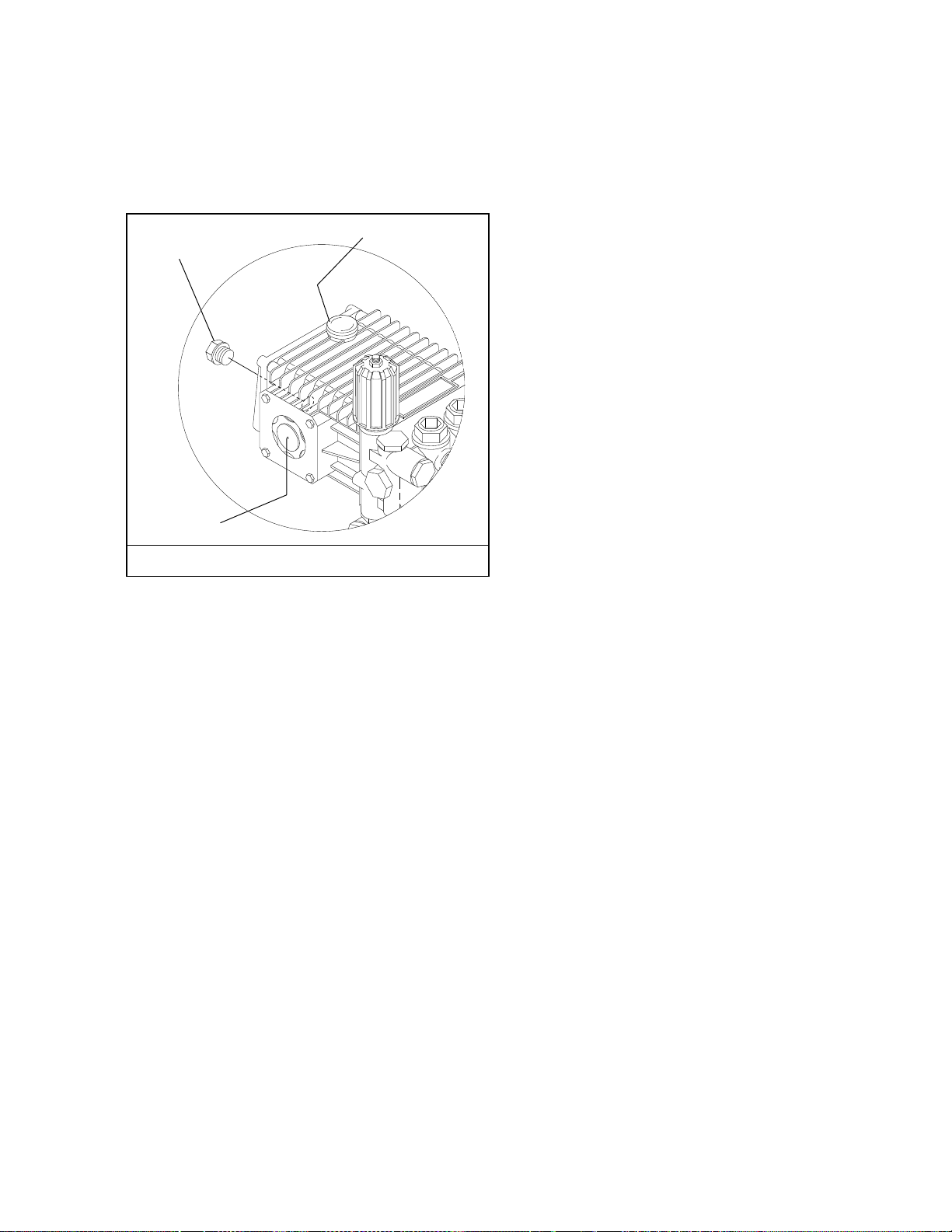
Figure 8 - Detergent Injector Valve
DETERGENT CONTROL KNOB
WATER ADJUSTMENT KNOB
DETERGENT
ON
DETERGENT
OFF
WATER
DECREASE WATER
INCREASE
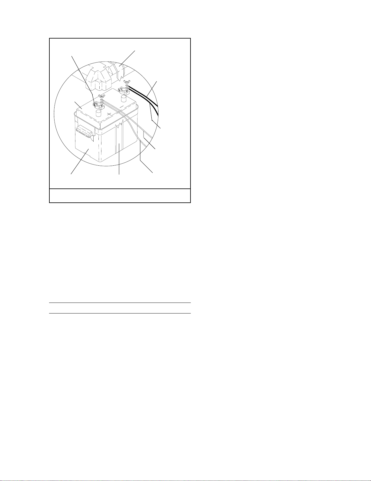
IMPORTANT:The trigger gun provided with this pres-
sure washer is equipped with a manual trigger lock
to prevent accidental operation of the trigger gun.
(Refer to Figure 7.)The manual trigger lock should be
used whenever the trigger gun is not in use.
To Start
DANGER:DO NOT point wand or trigger gun at your-
self or at any person. Bodily injury may result from
water under high pressure.
WARNING:Wear eye, ear, hand, foot and skin protec-
tion at all times while operating pressure washer.
IMPORTANT:The watermust beturned on beforestart-
ing. Running the pump dry will cause damage and
void warranty.
IMPORTANT: DO NOT allow the machine to run with
trigger of the trigger gun released for more than
10 minutes at any one time or damage to pump may
occur.
1. Turn ON water supply.
2. Hold wand firmly, release trigger of trigger gun.
3. Place engine ON/OFF switch in the ON position.
4. Open fuel shutoff valve (if so equipped).Move choke
lever to FULL CHOKE position, (choke may not be
neededonwarm engine).Move throttle levertoHALF
THROTTLE position.
5. Pulltheropestarter slowlyuntilresistance is felt,then
pull briskly.Do not allow the rope starter to snap back
against the engine. Return it gently to prevent dam-
age to the starter.
6. When the engine starts, move choke lever until
engine runs smoothly. When engine warms, move
choke lever to NO CHOKE position. Move throttle
lever to FULLTHROTTLE position.
IMPORTANT:To allow for proper battery charging,the
throttle control must be kept in the full throttle posi-
tion during operation.
NOTE:If engine fails to start, refer toTroubleshooting
Guide in this manual.
7. Squeeze trigger of trigger gun and allow air to purge
from system.
8. If HOT water is desired, adjust the thermostat to the
proper temperature and turn burner switch ON.The
burnerwilllightimmediatelywith asmallpuff ofsmoke.
You may need to initially adjust your burner for peak
performance.SeeOil Burner sectionunderInstalla-
tion.If smoke continues, contact Customer Service
at 1-303-792-5200. When the trigger of the trigger
gun is released or when the thermostat temperature
setting is reached, the burner will automatically turn
off.
To Clean
DANGER: DO NOT place hands or fingers in front of
high pressure spray. Bodily injury may result.
The detergent injector valve operates by reducing the
volumeofwater,thusavacuumis achievedand detergent
is drawn into the system.DO NOT reduce the water inlet
flow so the pump cavitates due to water starvation.
Operating a pump with insufficient water will damage
the pump seals.
1. Insert detergent inlet line into container of mixed
detergent.
2. Completely open detergent control knob located on
the side of the detergent injector valve. Refer to
Figure 8.
3. Start the detergent suction by rotating the water
adjustment knob of the detergent injector valve.
Referto Figure 8.Turning the knob counterclockwise
will pull detergent into the system. The flow may be
observed through the clear detergent line.Secure the
knob position with the knurled nut.
4. Thesidedetergentcontrol knob can nowbe adjusted
to meter the desired amount of detergent.
5. Wash from the bottom to the top, using side to side
motions.This washes away heavy dirt and allows the
detergent to soak as you work toward the top.
6. Do not wash at a 90oangle to the work (straight at it).
This will allow water to splash back at you and
reduces your cleaning power. Wash at a 30oto 60o
angle to the work.This will allow the water to splash
away from you and the water will wash the dirt away
faster and easier.
7. Use the width of the spray pattern to wash in a wide
path. Overlap spray paths for complete coverage
washing from side to side, using slow, steady
motions.

Page8 Hotsy 1065A/1065SS
ON
OFF
BURNER TEMPERATURE
FUNNEL
GARDEN HOSE CONNECTOR
8. The nozzle should be 12" to 24" from work, closer for
tough areas. Be careful on painted or delicate sur-
faces, the pressure may damage surface if nozzle is
too close.
9. Smallpartsshouldbe washed inabasketsothe pres-
sure does not push them away. Larger, lightweight
parts should be clamped down so the pressure does
not push them away.
10. Turn the side detergent control knob clockwise (CW)
for detergent decrease. Wait for detergent to clear.
Always rinse with cold water after using detergent.
Rinse from the top to the bottom to prevent detergent
from dripping onto a rinsed area.For the best results,
contact your Hotsy dealer to help you select the best
detergent for your application.
To Stop
1. Ifdetergentswereused, drawclear waterthrough the
detergent inlet line to purge detergent. Failure to do
so may clog detergent injector valve.
2. If burner was used, turn OFF burner switch and
allow pump to run cold water through coil for several
minutes.
3. Move throttle lever to idle position.
4. Turn engine ON/OFF switch to the OFF position.
5. Close fuel shutoff valve (if so equipped).
6. Turn water supply OFF.
7. Squeeze trigger of trigger gun to relieve system
pressure.
STORAGE
DANGER: DO NOT store flammable liquids (gasoline,
diesel fuel, solvents, etc.) near pressure washer, or
in non-ventilated areas.
Protect from freezing by storing in a heated area, or by
flushing the system with antifreeze (use an automotive
engine antifreeze or windshield washer solvent to
antifreeze). To flush the system with antifreeze, the
following steps are to be followed:
1. Connect the water supply hose to the garden
hose connector located on the pump. Turn on water
supply.
2. Place the detergent inlet line into a container of
antifreeze.
3. Hold wand firmly, release trigger of trigger gun.
4. Start engine. Place throttle lever in Full Throttle
position.
5. Squeeze trigger of trigger gun and allow water to
flow from the end of the wand.Watch for antifreeze to
be drawn through the detergent inlet line. Allow the
antifreeze to be drawn into the system for 5 to 10
seconds.
6. Release the trigger of the trigger gun and stop
engine.
7. Turn off water supply and disconnect water supply
hose from the pump.
8. Attach a short length of hose (approximately 3 feet
long) to the garden hose connector located on the
pump. Install a funnel in the other end of the hose as
shown in Figure 9.
Figure 9 - Winterizing
9. Hold wand firmly, release the trigger of the trigger
gun.
10. Start engine.Place throttle lever in the idle position.
11. Squeeze trigger on trigger gun.
12. Slowly pour antifreeze into the funnel. Continue to
add antifreeze until antifreeze flows from the end of
the wand.
13. Squeeze and release the trigger of the trigger gun
several times to antifreeze the unloader system.
14. Release the trigger of the trigger gun. Stop engine.
15. Squeeze the trigger of the trigger gun to relieve sys-
tem pressure.
For added protection, after antifreezing, disconnect the
pressurehose from themachineand removethecoil drain
plug(referto Figure 1 forlocation.)Aftercoilhas drained,
replace pressure hose and coil drain plug.If the pressure
washer is not to be used for an extended length of time, it
is recommended that the system be flushed with
antifreeze for rust protection. Refer to the Gasoline
Engine Manual for engine storage information.
MAINTENANCE
WARNING:Unauthorizedmachine modification oruse
of non-approved replacement parts may cause per-
sonal injury and/or property damage and will void the
manufacturer warranty.

Page9Hotsy 1065A/1065SS
OIL
OIL FILL/DIPSTICK
OIL DRAIN
PLUG
OIL GAUGE
Pump
Lubrication: To lubricate pump, use 30W non-detergent
oilfor pumpcrankcase.Crankcasemust be filledtocenter
of red dot on oil gauge found on the side of the pump,
referto Figure 10.Duringthe break-in-period,makesure
the oil is changed after the first 40 hours of operation.
After that, replace oil every 3 months or 500 hours of
operation, whichever comes first.
Proper Pump Care:
• DO NOT pump acids.
• DO NOT allow pump to run dry.
•Winterize if storing in freezing temperatures, refer
to Storage for details.
•Use a water softener on the water system if known
to be high in mineral content.
•Use only high quality detergents and follow manu-
facturer's mix recommendations.
•Flush the system with clear water immediately
after using detergent solutions.
•Clean filter screen on detergent inlet line
periodically.
•Flush the pressure washer system with antifreeze
if storing for an extended period of time, refer to
Storage for details.
Gasoline Engine
Refer to the provided Gasoline Engine Manual for
recommended maintenance.
Oil Burner
Blower Motor:Inspect the motor brushes for wear every
250 hours of operation and replace when 1/8" to 1/4"
brush material remains. DO NOT allow the brushes to
Figure 10 - Pump Lubrication
wear out completely or motor damage will occur.Refer to
Figure 13.The motorbearingsare permanentlylubricated
and will not require any additional lubrication.
Relief Valve
WARNING:The relief valve on this pressure washer
has been factory set and sealed and is a field nonad-
justable part.Tampering with the factory setting may
cause personal injury and/or property damage, and
will void the manufacturer warranty. For replacement
parts refer to Figure 18.
Unloader Valve
WARNING: The unloader valve on this pressure
washer has been factory set and sealed and is a field
nonadjustable part. Tampering with the factory set-
ting may cause personal injury and/or property dam-
age, and will void the manufacturer warranty. For
replacement refer to Figure 15.
Burner Fuel Filter
Drain any water which has accumulated in fuel filter
and clean or replace filter element as needed. Refer to
Figure 13.
Heating Coil
Coil Descaling:In hard water areas,scale buildupwithin
the heating coil will occur. Scale deposits will decrease
the water temperature rise and may eventually clog the
heating coil. Contact your local service center when
descaling is needed.
Coil Desooting: Poor grades of fuel oil or inadequate
combustion air will cause heavy soot buildup on the
outside surface of the heating coil. These deposits will
insulate the coil.This will restrict the air flow through the
coil, further aggravating the soot buildup. Contact your
local service center when desooting is needed.
Hour Meter
An optional hour meter (P/N 783865) is available for use
ontheModel 1065A/1065SS.This hour meter willmonitor
the total hours of operation of the pressure washer to
signal when routine maintenance is required.
Battery
Refer to battery manufacturer’s literature for recom-
mended maintenance.

Page10 Hotsy 1065A/1065SS
TROUBLESHOOTING GUIDE
SYMPTOM POSSIBLE CAUSES CORRECTIVE ACTION
Gas engine will not run. Out of gas. Replenish supply. Use only recom-
mended fuels. Refer to Before Start-
ing under Operation.
Fuel valve closed (if so equipped). Open valve.
Loose spark plug wire. Reconnect.
Choke or throttle set incorrectly. Refer to To Start under Operation.
Engine ON/OFF switch in OFF
position. Place engine ON/OFF switch in ON
position.
Low engine oil level. Replenish supply. Engine will not start
or run if oil is low (on engines equipped
with low oil protection).
Refer to provided gasoline engine manual for additional troubleshooting.
Pressure washer runs
but won't spray. Trigger of trigger gun released. Squeeze trigger.
Water supply not turned on. Open water supply valve.
Clogged pressure nozzle. Clean pressure nozzle opening.
Low spray pressure at
pressure nozzle. Inadequate water supply. Fully open faucet. Check for kinked or
damaged hose. Use 5/8 inch minimum
hose. Check for debris clogging inlet
screen.
Partially clogged or damaged
pressure nozzle. Clean or replace.
Air being drawn through detergent
inlet line. Refill detergent container. Ensure that
pick-up screen is fully immersed.
Detergent injector valve not set
correctly. Refer to To Clean for settings.
Uneven spray pattern. Partially clogged or damaged
pressure nozzle. Clean or replace.
Pressure washer will
not produce hot water. Burner switch in OFF position. Place switch in ON position.
Inadequate fuel supply. Refill fuel tank. Use only recommend-
ed fuels. Refer to Before Starting
under Operation.
Inadequate water supply. Fully open faucet. Check for kinked or
damaged hose. Use 5/8 inch minimum
hose. Check for debris clogging inlet
screen.
Trigger of trigger gun released. Squeeze trigger.Water must be spray-
ing for burner to light.

Page11Hotsy 1065A/1065SS
IMPORTANT
If the pressure washer demonstrates other symptoms or the corrective actions
listed do not correct the problem, contact the local authorized Hotsy Service
Center.The Hotsy Service Center can be identified by contacting:
Customer Service Department
The Hotsy Corporation
21 InvernessWay East •Englewood, Colorado 80112
(303) 792-5200
TROUBLESHOOTING GUIDE
SYMPTOM POSSIBLE CAUSES CORRECTIVE ACTION
Pressure washer will not
produce hot water.
...continued
Thermostat set too low. Adjust thermostat to desired temp-
erature.
Blown fuse. Replace. Fuse is located in Control
Box.
Engine is running too slow. Move throttle lever to full throttle
position.
Battery charge is low. Charge battery or replace if necessary.
Poor or no detergent
flow. Inadequate detergent supply. Refill detergent container. Ensure that
pick-up screen is fully immersed.Open
detergent valve.
Detergent screen or hose clogged. Clean. Always start with a clean deter-
gent container.
Detergent injector valve not set
correctly. Refer to To Clean for settings.
Clogged detergent injector check
valve. Clean check valve at detergent injector
inlet.
Poor cleaning. Improper detergent concentration or
mixing. Mix detergent per manufacturer's
instructions. Ensure that powdered
detergents are fully dissolved.
Wrong detergent for the application. Select appropriate detergent.
Rinsing with hot water. A final rinse with cold water will reduce
water spotting.

Page12 Hotsy 1065A/1065SS
FOR HELP OR ADDITIONAL INFORMATION, CONTACT:
Customer Service Department
The Hotsy Corporation
21 Inverness Way East
Englewood, CO 80112
(303) 792-5200
When ordering from your dealer, please provide the following:
Model Number: 1065A/1065SS
Machine Serial Number: ________________________________
Component Part Number: _______________________________
Description: __________________________________________

Page13Hotsy 1065A/1065SS
Ref. No. Part No. Description Qty.
1 961532 Tubing 3/8"
✽
2 823987 Hose Clamp 1
3 213044 Burner Exhaust Vent 1
4 268004 Insulation 1
5 860102 Retaining Ring 1
6
■
Flat Washer 5/16" 7
7
■
Locknut 5/16" - 18 4
8Fig. 19 Fuel Tank Assembly 1
9
■
Bolt 1/4" - 20 x 1/2" 2
10
■
Flat Washer 1/4" 6
11 646113 Decal Detergent Metering 1
12 834159 Decal Hotsy Detergents 1
13 826167 Strain Relief 2
14 703127 Strain Relief Nut 2
15
■
Locknut 1/4" - 20 4
16 375292 Mounting Plate 1
Ref. No. Part No. Description Qty.
17 220119 Battery Box 1
18 890904 Battery Terminal 2
19 834154 Decal Winterize 1
20 Fig. 13 Burner Assembly 1
21 799362 Crownlock Nut 5/16" - 18 3
22 Fig. 17 Coil Inlet Assembly 1
23 834415 Decal Warnings 1
24 Fig. 15 Pump Assembly 1
25
●■
Bolt 3/8" - 16 x 1" 4
26
■
Lock Washer 3/8" 4
27 Fig. 14 Control Box Assembly 1
28 Fig. 18 Coil Outlet Assembly 1
29 375445 Chassis 1
✽
Order amount needed in feet.
■
Standard hardware item available locally.
●
Use thread locking compound.
Figure 11 - Machine Assembly, Right Side /Front View
OIL
ON
OFF
BURNERTEMPERATURE
CAUTION: DRAIN OR
WINTERIZE DURING
FREEZING
TEMPERATURES,
COSULT MANUAL
345
29
6,7
8,9,10
11
12
13,14
10,15,16,17,18
19
20,6,21
24,25,26
22
23
27
28
1,2

Page14 Hotsy 1065A/1065SS
OPERATINGINSTRUCTIONS
IMPORTANT
TOALLOWFORPROPERBATTERY
CHARGINGTHETHROTTLECONTROL
MUSTBEKEPTINTHEFULL
THROTTLEPOSITIONDURINGOPERATION
HONDA
GX340
11.
O
GASOLINE
CAUTION
DONOTFILLGASOLINE
TANKWHILE ENGINEIS
RUNNINGORENGINEIS
HOT
DANGER
CAUTION:
HOT
SURFACE
Ref. No. Part No. Description Qty.
17 859815 Grommet (Nozzle Holder) 3
18 815329 Snap Bushing 1
19 860232 Voltage Regulator 1
20 218189 Regulator Harness 1
21
■
Washer Flat 1/4" 2
22
■
Locknut 1/4" - 20 2
23 983013 Wheel 4
24 817322 Hubcap 4
25 848616 Push Nut 4
26
■
Flat Washer 5/8" 8
27 815329 Snap Bushing 3
28 661282 Engine 1
29 890783 Tag Gasoline Engine 1
NS
■
Flange Nut 5/16" - 18
(Coil Tank)
4
NS
■
Fender Washer 5/16"
(Coil Tank)
4
NS = Not Shown
■
Standard hardware item available locally.
1234 56
19,20,21,2223,24,25,26
Ref. No. Part No. Description Qty.
1 232025 Decal Battery 1
2 444462 Decal Caution Gasoline 1
3 646115 Decal Hot Surface 1
4 646026 Decal Carbon Monoxide 1
5 834416 Decal Operating Instruction 1
6 240834 Coil 1
7 824115 Vent Clip 4
8 375443 Coil Tank (1065A) 1
375446 Coil Tank (1065SS) 1
9 926598 Rivet 8
10 Fig. 20 Trigger Gun/Wand Assembly 1
11 829979 Hotsy Logo Plate 2
12 646095 Decal Troubleshooting 1
13 867207 Pressure Hose 1
14 268013 Insulation 1
15 213191 Pancake Insulation 1
16 859806 Grommet 1
Figure 12 - Machine Assembly, Right Side View
7
8
11
12 13
14
15
16
17
18
27
28
29
10
9

Page15Hotsy 1065A/1065SS
Ref. No. Part No. Description Qty.
1 784353 Motor 1
2 661302 Electrode (Pair) 1
3 799089 Nozzle 1
4 890906 Ignitor 1
5 944422 Solenoid Valve 1
6 880806 Fuel Line 1
7 919791 Fuel Pump 1
8 644750 Street Elbow 1/4" 1
9 698200 Nipple 1/4" x 2-1/2" 1
10 615279 Reducer Bushing 3/8" x 1/4" 1
11
✪
851080 Fuel Filter 1
12 698023 Nipple 3/8" x 1/4" Hose 1
13 698020 Nipple 1/4" x 1/4" Hose 1
14 901230 Solenoid Metering Bolt 1
15 615851 Burner 1
16 753167 Brush Kit 2
Ref. No. Part No. Description Qty.
NS 825924 Coupling 1
NS 676865 Blower Fan 1
NS 875312 Relay 1
NS 895312 Timer 1
NS 890916 Terminal Block 1
NS 877667 Tune Up Repair Kit 1
NS 826167 Strain Relief 1
NS 703127 Strain Relief Nut 1
NS
■
Screw #6 - 32 x 1" 1
NS
■
Locknut #6 - 32 1
NS = Not Shown
■
Standard hardware item available locally.
Replacement Parts
✪
875490 Filter Element 1
Figure 13 - Burner Assembly
ELECTRODE SETTINGS
ELECTRODE NOZZLE
5/16" 3/16"
AIR CONE
1/4" 1/8"
123 4
5
6
7
8
9
10
11
12
13
14
15
16

Page16 Hotsy 1065A/1065SS
ON
OFF
BURNER TEMPERATURE
Ref. No. Part No. Description Qty.
1 875465 Burner Switch 1
2 645932 Decal Control Box 1
3 835150 Thermostat Dial 1
4 915390 Thermostat Mounting Plate 1
5 615413 Control Box Front 1
6 630649 Channel 2
7 615414 Control Box Back 1
8 860140 Isolation Relay 1
9
■
Screw 4 mm x 6 mm 2
10 645990 Bridge Rectifier 1
11 676638 Fuse 30A 1
12 707146 Fuse Holder 1
Ref. No. Part No. Description Qty.
13 955940 Thermostat 1
14
■
Locknut 1/4" - 20 4
15
■
Bolt 1/4" - 20 x 3/4" 4
16 826184 Strain Relief 4
17
✪
875651 Pressure Switch 1
18 847750 Wire Cover
✽
■
Standard hardware item available locally.
✽
Order amount needed in feet.
Replacement Parts
✪
753134 O-Ring Kit 1
✪
875653 Switch 1
Figure 14 - Control Box Assembly
17
18
16
15 14 13 11,12
10
9
8
7654321

Page17Hotsy 1065A/1065SS
OIL
WARNING
Ref. No. Part No. Description Qty.
1 829772 Pump Fig. 16 1
2 644802 Street Elbow 3/8" 1
3 844758 Street Elbow 1/2" 1
4 600071 Reducing Nipple 1/2" x 3/8" 1
5 873596 Detergent Injector Valve 1
6 875575 Garden Hose Connector Spring 1
7 801126 Garden Hose Connector 1
8 856035 Garden Hose Connector Gasket 1
9 823989 Hose Clamp 1
10 961534 Tubing 1/4"
✽
Ref. No. Part No. Description Qty.
11 935159 Filter Screen 1
12 921422 Thermal Relief Valve 1
13 644751 Elbow 3/8" 1
14
✪
921425 Unloader Valve 1
15 890769 Tag Unloader 1
16 707189 Hose 3/8" x 28" 1
✽
Order amount needed in feet.
Replacement Parts
✪
753073 Unloader Repair Kit 1
Figure 15 - Pump Assembly
12 11
10
9
8
7
6
5
4
3
2
1
16
15
14
13

Page18 Hotsy 1065A/1065SS
Ref. No. Part No. Description Qty/Pump
1 753084 Valve Plug Kit 6
2 753083 Check Valve Kit 6
Ref. No. Part No. Description Qty/Pump
3 753079 Oil Seal Kit 3
4 753085 Plunger Seal Kit 3
Figure 16 - Pump, Exploded View

Page19Hotsy 1065A/1065SS
Ref. No. Part No. Description Qty.
3 715755 Coil Drain Plug 1
Figure 17 - Coil Inlet Assembly
Ref. No. Part No. Description Qty.
1 698247 Hex Nipple 1/2" x 2" 1
2 754717 Tee 1/2" 1
1
23

Page20 Hotsy 1065A/1065SS
Ref. No. Part No. Description Qty.
1 698247 Hex Nipple 1/2" x 2" 1
2 875555 Relief Valve Seat 1
3 799501 Elbow 1/4" x 3/8" Hose 1
4 780565 Copper Washer 2
5 915630 Plug 3/8" 2
Ref. No. Part No. Description Qty.
6 783845 Relief Valve Manifold 1
7
■
Screw 4mm x 6 mm 1
8 644802 Street Elbow 3/8" 1
9 630720 Relief Valve Cartridge 1
■
Standard hardware item available locally.
Figure 18 - Coil Outlet Assembly
9
8
4,5
7
6
4,5
123
This manual suits for next models
1
Table of contents
Other Hotsy Pressure Washer manuals

Hotsy
Hotsy HC-232439 User manual

Hotsy
Hotsy 1800 Series User manual

Hotsy
Hotsy HSS-503089E User manual

Hotsy
Hotsy BD-405039E User manual

Hotsy
Hotsy EP-2010 User manual

Hotsy
Hotsy DB-2527 User manual

Hotsy
Hotsy 790SS Service manual

Hotsy
Hotsy BDE-505009B User manual

Hotsy
Hotsy HHD 5/30 G User manual

Hotsy
Hotsy BX-2527 User manual

Hotsy
Hotsy 781SS Service manual

Hotsy
Hotsy 555SS Service manual

Hotsy
Hotsy 555SS Service manual

Hotsy
Hotsy 555 HE User manual

Hotsy
Hotsy 1800 Series User manual

Hotsy
Hotsy 1260SS User manual

Hotsy
Hotsy ET-201006D User manual

Hotsy
Hotsy TRB Series User manual

Hotsy
Hotsy Xpert-HD 2.3/23 p User manual

Hotsy
Hotsy 1700 Series User manual