Hotsy 781SS Service manual

OPERATING INSTRUCTIONS
AND PARTS MANUAL
Thank you for purchasing a Hotsy PressureWasher.This manual covers the operation and mainte-
nance of your pressure washer. All information in this manual is based on the latest product informa-
tion available at the time of printing. Hotsy, Inc. reserves the right to make changes at any time without
incurring any obligation.
Read instructions carefully before attempting to assemble, install, operate or service this pressure
washer. Failure to comply with instructions could result in personal injury and/or property damage!
MODELS 781SS,
871SS, 921SS
SERIAL NUMBER:
DATE PURCHASED:
FOR SALES AND SERVICE, PLEASE CONTACT:
L
I
S
T
E
D
®


871SS SPECIFICATIONS
●Pump Volume At Pump Head: 2.71 GPM/162.6 GPH
●Pump Pressure At Pump Head: 2400 PSI
●Burner Type: Fuel Oil Fired, 248,500 BTU/Hr.
●Burner Fuel Pressure: 140 PSI
●Machine Voltage: 7 HP Robin Subaru, Manual Start
●Machine Weight: 291 Lbs.
●Shipping Weight: 330 Lbs.
●Exhaust Stack Size: 8"
●MachineDimensions:Length=48",Width=27",Height=42.5"
781SS SPECIFICATIONS
●Pump Volume At Pump Head: 2.5 GPM/150 GPH
●Pump Pressure At Pump Head: 2000 PSI
●Burner Type: Fuel Oil Fired, 248,500 BTU/Hr.
●Burner Fuel Pressure: 140 PSI
●Machine Voltage: 6 HP Robin Subaru, Manual Start
●Machine Weight: 287 Lbs.
●Shipping Weight: 326 Lbs.
●Exhaust Stack Size: 8"
●MachineDimensions:Length=48",Width=27", Height=42.5"
921SS SPECIFICATIONS
●Pump Volume At Pump Head: 3.0 GPM/180 GPH
●Pump Pressure At Pump Head: 3000 PSI
●Burner Type: Fuel Oil Fired, 248,500 BTU/Hr.
●Burner Fuel Pressure: 140 PSI
●Machine Voltage: 9 HP Robin Subaru, Manual Start
●Machine Weight: 385 Lbs.
●Shipping Weight: 415 Lbs.
●Exhaust Stack Size: 8"
●Machine Dimensions: Length=47", Width=31", Height=49"

Page4 Hotsy 781SS, 871SS, 921SS • 97-6642 • Rev.9/04
Figure 1 - Machine Component Layout (871SS Shown)
TRIGGER
GUN
CONTROL
BOX
HIGHPRESSURE
HOSE
WAND
BURNEREXHAUST
VENT
COILDRAIN
PLUG
HOUR
METER
ENGINEFUEL
TANK
BURNER
PUMP
DETERGENT
INJECTOR
ANTI-SIPHON
VALVE
DETERGENT
INLETLINE
BURNERFUEL
TANK
HIGHPRESSURE
NOZZLES
THERMOSTAT
BURNERSWITCH
ENGINE

Page5Hotsy 781SS, 871SS, 921SS • 97-6642 • Rev.9/04
INTRODUCTION
Thank you for purchasing a Hotsy Pressure Washer.
This manual covers the operation and maintenance of
the 781SS, 871SS and 921SS washers. All informa-
tion in this manual is based on the latest product infor-
mation available at the time of printing.
Hotsy, Inc.reserves the right to make changes at any
time without incurring any obligation.
Owner/User Responsibility:
Theowner and/orusermust have anunderstandingof
themanufacturer’soperatinginstructions andwarnings
before using this Hotsy pressure washer.Warning in-
formationshouldbeemphasizedandunderstood.Ifthe
operator is not fluent in English, the manufacturer’s in-
structionsand warnings shall be readtoand discussed
with the operator in the operator’s native language by
the purchaser/owner, making sure that the operator
comprehends its contents.
Owner and/or user must study and maintain for future
reference the manufacturers’instructions.
This manual should be considered a permanent
part of the machine and should remain with it if
machine is resold.
When ordering parts,please specify model and
serial number.
ASSEMBLY
Unpacking
Unpack carefully. Wear safety glasses or goggles while
unpacking, assembling, or operating pressure washer. If
there are missing components or hidden damage,
immediately contact carrier concerning discrepancies.
1. Cut strapping band from pressure washer and pallet.
2. Remove pressure washer from pallet.
Parts Included
•Pressure Washer
•Pressure Hose
•Wand
•Operating Instructions and Parts Manual
•Gasoline Engine Manual
•Parts Bag Containing:
■Pressure Nozzles (3 Ea.)
■Quick Disconnects (2 Ea.)
■Quick Disconnect Plug
■Trigger Gun
Tools Required
•8" Adjustable Wrench
•Teflon Tape
•Flat Blade Screwdriver
Pressure Hose,Trigger Gun andWand
1. When assembling, use teflon tape on all threaded
plumbing connections to prevent leakage.
2. Install the pressure hose on the pressure washer as
shown in Figure 2.
3. Assemble wand components as shown in Figure 3.
NOTE: The pressure nozzle is not to be installed at
this time.
4. Make sure all plumbing connections are tight.
Figure 2 - Pressure Hose Installation to Coil
PRESSUREHOSE
RELIEFVALVE
Figure 3 - Pressure Hose Installation toTrigger Gun
TRIGGERGUN
QUICKDISCONNECT
QUICK
DISCONNECT
WAND
QUICKDISCONNECTPLUG
PRESSUREHOSE

Page6 Hotsy 781SS, 871SS, 921SS • 97-6642 • Rev.9/04
WARNING
RISKOF
ASPHYXIATION.
USETHISPRODUCT
ONLYINAWELL
VENTILATEDAREA.
IMPORTANT SAFETY
INSTRUCTIONS
WARNING:When using this machine basic precau-
tions should always be followed, including the fol-
lowing: CAUTION:To reduce the risk of
injury, read operating instruc-
tions carefully before using.
1.Readtheowner'smanualthor-
oughly. Failure to follow in-
structions could cause mal-
function and result in death,
serious bodily injury and/or
propertydamage.
2. Knowhowtostopthe machineandbleedpressures
quickly. Be thoroughly familiar with the controls.
3. Stay alert - watch what you are doing.
4. Allinstallationsmust comply with local codes.Con-
tact your electrician, plumber, utility company or
the selling distributor for specific details.
WARNING: Flammable liquids
can create fumes which can ig-
nitecausing property damage or
severe injury.
5. Risk of explosion - do not
sprayflammableliquids or op-
erateinanexplosivelocation.
Operate only where open
flame or torch is permitted.
WARNING:Donotplacemachine
near flammable objects when
the engine is hot.
WARNING: Keep water spray
awayfromelectrical wiring or fa-
tal electric shock may result.
Read warning tag on electrical
cord.
WARNING: Spray gun kicks back. Hold with both
hands.
6. Grip cleaning wand securely with both hands be-
fore starting the cleaner. Failure to do this could
resultin injury from a whipping wand.
WARNING: Risk of fire. Do not
addfuelwhenthemachineisop-
erating.
7. Allowenginetocoolfor2min-
utes before refueling. If any
fuelisspilled,makesurearea
is dry before testing spark
plug or starting the engine.
(Fire and/or explosion may
occur if this is not done.)
Gasolineenginesonmobile or portableequipmentshall
berefueled:
a. Outdoors;
b. Withthe engine on the equipmentstopped;
c. With no source of ignition within 10 feet of the
dispensingpoint;
d. With an allowance made for expansion of the
fuelshouldtheequipmentbeexposedtoahigher
ambienttemperature.
Inanoverfillingsituation,additionalprecautionsare
necessarytoensure that the situationishandled in
asafemanner. WARNING:Riskofinjectionorse-
vere injury to persons - Keep
clear of nozzle — Do not touch
ordirectdischargestream atper-
sons.This machine is to be used
only by trained operators.
CAUTION: Hot discharge fluid.
Donottouchordirectdischarge
streamatpersons.
8. High pressure developed by these machines can
cause personal injury or equipment damage. Use
caution when operating. Do not direct discharge
streamatpeople,or severe injuryand/ordeathmay
result. WARNING: High pressure can
cause paint chips or other par-
ticlesto become airborne andfly
at high speeds.
9. Eye safety devices and foot
protectionmustbe wornwhen
usingthis equipment.
10. Never make adjustments on
machinewhilein operation.
WARNING: Use only in well ven-
tilated areas. Failure to observe
this warning could cause a loss
of consciousness or death.
11. Avoid installingin small areas
ornearexhaustfans. Exhaust
contains poisonous carbon
monoxidegas;exposuremay
cause loss of consciousness
andmay lead todeath. It also
containschemicals known,in certain quantities,to
cause cancer, birth defects or other reproductive
harm.
12. Do not operate with the spray gun in the off posi-
tionforextensiveperiodsof time as thismaycause
damageto the pump.
13. The best insurance against an accident is precau-
tionand knowledge of the machine.
WARNING
KEEP WATER SPRAY
AWAY FROM
ELECTRICAL WIRING.
WARNING
RISKOFEXPLOSION:
USECAUTIONWHEN
REFUELING.
READ OPERATOR’S
MANUALTHOROUGHLY
PRIOR TO USE.
CAUTION
WARNING
RISK OF EXPLOSION:
DO NOT SPRAY
FLAMMABLE LIQUIDS.
WARNING
HIGHPRESSURE
STREAMCANPIERCE
SKINANDTISSUES.
WARNING
USEPROTECTIVE
EYEWEARWHEN
OPERATING.

Page7Hotsy 781SS, 871SS, 921SS • 97-6642 • Rev.9/04
14. Hotsy will not be liable for any changes made to
ourstandardmachines,oranycomponentsnotpur-
chased from Hotsy.
15. Read engine safety instructions provided.
16.Neverrunpumpdryorleavetriggergunclosedlonger
than 5 minutes.
17. Inlet water must be from a cold, clean fresh city
watersupply. WARNING: Only use recom-
mended fuel. Using other fuels
mayresult inaserious explosion
causing personal injury, prop-
erty damage or loss of life.
18. Use No.1 or No.2 heating oil
(ASTM D306) only. NEVER
use gasoline in your fuel oil
tank. Gasoline is more com-
bustiblethanfueloilandcould
result in a serious explosion. NEVER use crank-
caseorwasteoil in yourburner assembly.Fuel unit
malfunctioncould result from contamination.
19. Do not confuse gasoline and fuel oil tanks. Keep
properfuel in propertank.
20. Protect machine from freezing.
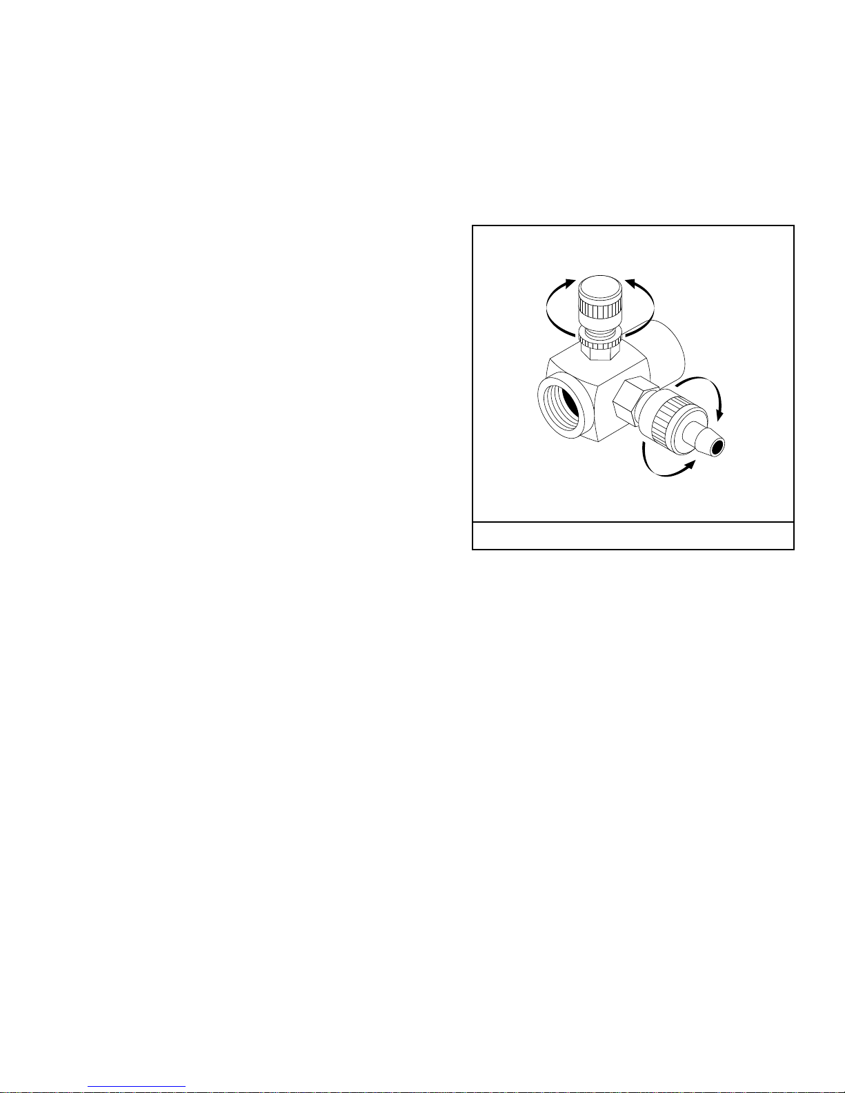
21. Be certain all quickcoupler fittings are securedbe-
fore usingpressure washer.
22. Do not allow acids, caustic or abrasive fluids to
passthrough the pump.
23. Toreducetherisk of injury,closesupervision is nec-
essarywhena productisusednearchildren.Donot
allow children to operate the pressure washer.This
machinemustbe attended during operation.
24. Donotoperatethisproduct when fatigued orunder
the influence of alcohol or drugs. Keep operating
area clear of all persons.
25. Protect highpressure hose fromvehicle traffic and
sharpobjects.
26. Beforedisconnectinghighpressurehosefromwater
outlet,turnburneroffandpullthetriggeronthespray
gun allowing water to cool to below 100° F before
stopping machine.Then open the trigger gun to re-
lievepressure.Failuretoproperlycooldownormain-
taintheheatingcoilmayresultina steamexplosion.
27. Donotoverreachorstandonunstablesupport.Keep
good footing and balance at all times.
28. This machine must be attendedduring operation.
INSTALLATION
Getting Started
IMPORTANT: Proper initial installation of equipment
will assure more satisfactory performance, longer
service life, and lower maintenance cost.
IMPORTANT: The use of a backflow preventer on
the water supply hose is recommended and may be
required by local code.
The pressure washer should be run on a level surface and
in a protected area where it is not readily influenced by
outsideforcessuchasstrong winds,freezingtemperatures,
rain,etc.Thepressure washershouldbelocated to assure
easy access for filling of fluids, adjustments and
maintenance.Normal precautions should be taken by the
operator to prevent moisture from reaching the pressure
washer.Itisrecommendedthatapartitionbemadebetween
the wash area and the pressure washer to prevent direct
spray from the wand from coming in contact with the
pressure washer. Moisture reaching the equipment will
reduce the pressure washer’s service life. All installations
mustcomplywiththelocalcodescoveringsuchinstallations.
Venting
DANGER: DO NOT run machine indoors or in an
enclosed area, as exhaust fumes may be hazardous
to your health.
DANGER: DO NOT operate machine in areas where
flammable vapors (gasoline, solvents, etc.) may be
present, as this machine may ignite the vapors.
CAUTION: All venting must be in accordance with
applicable federal and state laws, and local ordi-
nances. Consult local heating contractors.
If the pressure washer is to be used in an enclosed area, a
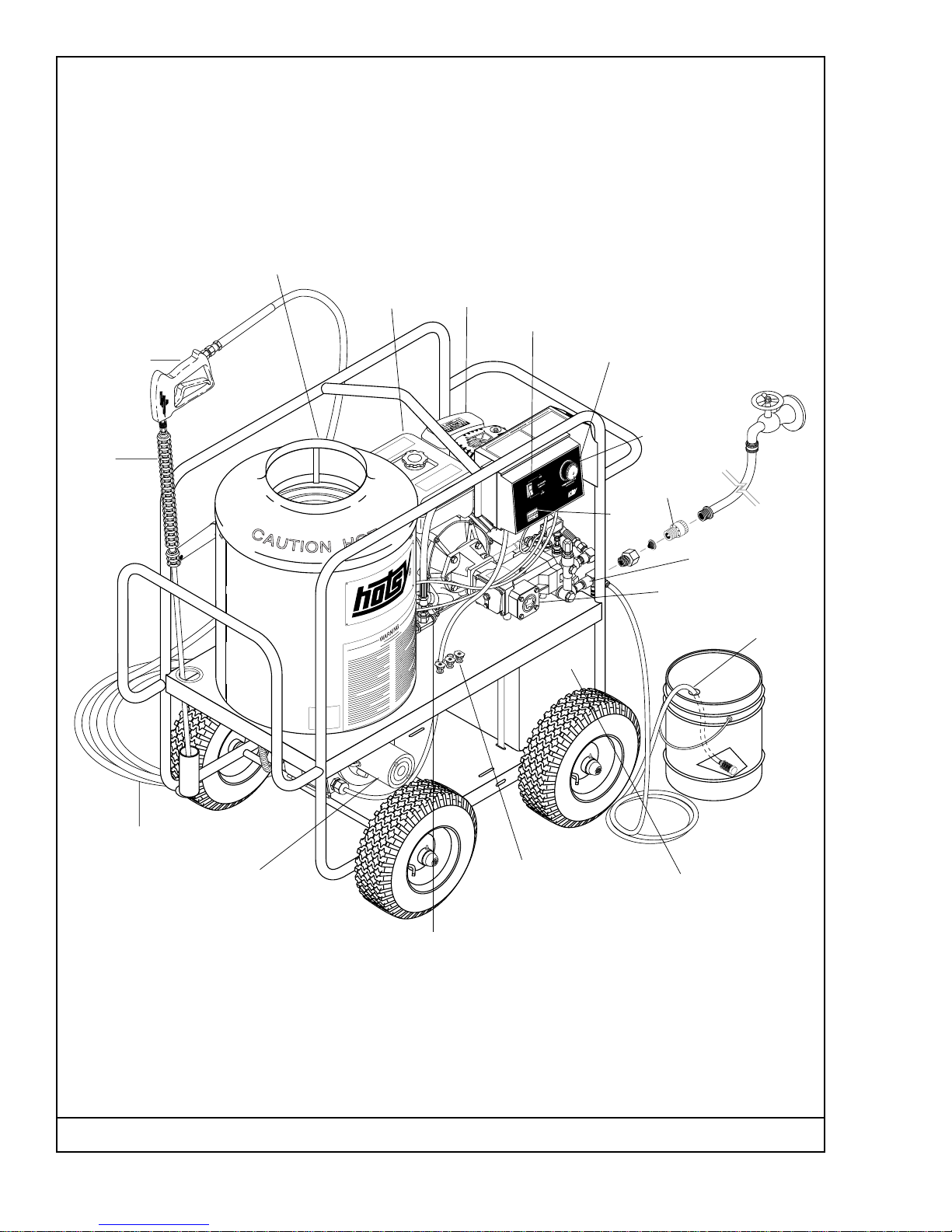
flue must be installed to vent burner and engine exhaust
to the outside atmosphere. Be sure the flue is the same
size as the burner exhaust vent on the pressure washer.
SeeFigure 1forlocation.Poordraftwillcausethepressure
washer to soot and not operate properly. When selecting
the location for installation, beware of poorly ventilated
locations or areas where exhaust fans may cause an
insufficient supply of oxygen. Proper combustion can only
be obtained when there is a sufficient supply of oxygen
available for the amount of fuel being burned. If it is
necessary to install the machine in a poorly ventilated
area, outside fresh air may have to be piped to the burner
and a fan installed to bring sufficient air into the machine.
Locate the pressure washer so that the flue will be as
straight as possible and protrude through the roof at a
proper height and location to provide adequate draft.This
oil fired pressure washer must have a draft regulator
installed in the flue (available from most heating
contractors). A draft regulator will permit proper upward
flow of exhaust flue gases.
In addition, the pressure washer should never be operated
inanenclosedareawherehighambienttemperaturesexist.
Highambienttemperatures(above100oF)cancauseengine
oil failure and will greatly reduce the engine’s performance.
Gasoline Engine
The gasoline engine is preset for operation at altitudes
below 3000 feet above sea level. If operated at higher
altitudes, it may be necessary to install a high altitude
main jet in the carburetor. Contact an authorized engine
sales and service center for details.
WARNING
RISK OF FIRE OR
EXPLOSION:USE
VAPORFUELONLY.

Page8 Hotsy 781SS, 871SS, 921SS • 97-6642 • Rev.9/04
OPERATION
Before Starting
1. Read all manualsprovidedwith this pressure washer.
Become familiar with location and function of all
operating and safety controls.
WARNING: Check hoses, fittings, wand, trigger gun
and fuel connections daily for signs of wear, cracks
and looseness, and replace as required.
2. Connect water supply hose to the garden hose con-
nector located on pump.The water faucet and supply
hose must be capable of providing a minimum of 3.5
gallons per minute (GPM).
3. Filloilburner fuel tank.Use kerosene,#1gradehome
heatingoil,#1or#2dieselfuel.DO NOT USE GASO-
LINE, CRANKCASE OIL DRAININGS, OR WASTE
OIL.
WARNING: DO NOT fill engine fuel tank while engine
is running or hot. Let engine cool before refueling
or spontaneous fire may result. Fuel spillage or va-
pors could ignite if engine is hot.
4. Fill the engine fuel tank. Do not overfill, fill to the
bottom of filler neck only. Use lead free gasoline
minimum 86 octane. DO NOT use gasoline contain-
ing more than 15% MTBE, 5% methanol or 10%
ethanol. Refer to the provided gasoline engine
manual for additional details.
5. Check pump and engine oil levels.
6. If detergents are to be used, only use detergents
intendedfor pressure washers.Followinstructions on
the detergent container.
IMPORTANT: Before installing pressure nozzle on
initial start-up, turn on the water supply and allow
water to run from the end of the wand until clear to
prevent the pressure nozzle from clogging.
IMPORTANT: If the pressure washer has not been
used for an extended period of time,remove the pres-
sure nozzle from the end of the wand and turn on
water supply. Allow water to run from the end of the
wand until clear.
7. Install the proper pressure nozzle for your cleaning
needs on the end of wand, refer to Figure 5.
Pre-Operation Check
❑Pump Oil (SAE 30W non-detergent oil)
❑Cold Water Supply (3.5 gpm • 5/8" • 20 psi)
❑Hose, wand, nozzles (nozzle size per serial plate)
❑Water filter (intact, nonrestrictive)
❑Engine fuel (unleaded 86 or higher)
❑Engine oil (SAE 10W40)
❑Burner fuel (No.1 or No.2 home heating fuel or diesel)
Oil Burner
Burner Air Adjustment: The oil burner on this machine
is preset for operation at altitudes below 3000 feet. If
operated at higher altitudes, it may be necessary to
adjust the air shutter and air band setting. Adjust the air
shutter for a #1 or #2 smoke spot on the Bacharach
scale.
To adjust, start machine and turn burner ON (refer to
Operation for details). Loosen two locking screws found
in the air shutter openings (refer to Figure 4) and close
air shutter until black smoke appears from burner
exhaust vent. Note air shutter position. Next, slowly
open the air shutter until white smoke just starts to
appear.Turn air shutter halfway back to the black smoke
position previously noted. Tighten locking screws.
Figure 4 - Burner Adjustment
&
$
"
AIRSHUTTERLOCKINGSCREW
AIRSHUTTER
AIRBAND
AIRBAND
LOCKINGSCREW
AIRSHUTTER
LOCKINGSCREW
Figure 5 - Nozzle Installation/Manual Trigger Lock
MANUALTRIGGERLOCK
PRESSURE
NOZZLE
If the desired position cannot be obtained using only
the air shutter, lock the air shutter in as close a position
as can be obtained, then repeat the above procedure
on the air band setting.
CAUTION: If white smoke appears from burner
exhaust vent during start-up or operation, discon-
tinue use and readjust air bands.
NOTE: If a flue is installed, have a professional ser-
viceman adjust your burner for a #1 or #2 smoke
spot on the Bacharach scale.

Page9Hotsy 781SS, 871SS, 921SS • 97-6642 • Rev.9/04
The detergent injector valve operates by reducing the
volume of water, thus a vacuum is achieved and
detergent is drawn into the system. DO NOT reduce the
water inlet flow so the pump cavitates due to water
starvation. Operating a pump with insufficient water will
damage the pump seals.
1. Insert detergent inlet line into container of mixed
detergent.
2. Completely open detergent control knob located on
the side of the detergent injector valve. Refer to
Figure 6.
3. Start the detergent suction by rotating the water
adjustment knob of the detergent injector valve.
Refer to Figure 6. Turning the knob counterclock-
wise will pull detergent into the system. The flow
may be observed through the clear detergent line.
Secure the knob position with the knurled nut.
4. The side detergent control knob can now be ad-
justed to meter the desired amount of detergent.
5. Wash from the bottom to the top, using side to side
motions. This washes away heavy dirt and allows
the detergent to soak as you work toward the top.
6. Do not wash at a 90oangle to the work (straight at
it). This will allow water to splash back at you and
reduces your cleaning power. Wash at a 30°to 60°
angle to the work.This will allow the water to splash
away from you and the water will wash the dirt away
faster and easier.
7. Use the width of the spray pattern to wash in a wide
path. Overlap spray paths for complete coverage
washing from side to side, using slow, steady
motions.
8. The nozzle should be 12" to 24" from work, closer
for tough areas. Be careful on painted or delicate
surfaces,thepressure may damage surface if nozzle
is too close.
9. Small parts should be washed in a basket so the
IMPORTANT:The trigger gun provided with this pres-
sure washer is equipped with a manual trigger lock
to prevent accidental operation of the trigger gun.
(Refer to Figure 5.)The manual trigger lock should be
used whenever the trigger gun is not in use.
To Start
DANGER: DO NOT point wand or trigger gun at your-
self or at any person. Bodily injury may result from
water under high pressure.
WARNING: Wear eye, ear, hand, foot and skin pro-
tection at all times while operating pressure washer.
IMPORTANT: The water must be turned on before
starting. Running the pump dry will cause damage
and void warranty.
IMPORTANT: DO NOT allow the machine to run with
trigger of the trigger gun released for more than
10 minutes at any one time or damage to pump may
occur.
1. Turn ON water supply.
2. Hold wand firmly, release trigger of trigger gun.
3. Place engine ON/OFF switch in the ON position.
4. Open fuel shutoff valve (if so equipped). Move choke
lever to FULL CHOKE position, (choke may not be
neededonwarmengine). Move throttle lever to HALF
THROTTLE position.
5. Pulltheropestarter slowlyuntil resistance is felt,then
pull briskly.Do not allow the rope starter to snap back
against the engine. Return it gently to prevent dam-
age to the starter.
6. When the engine starts, move choke lever until
engine runs smoothly. When engine warms, move
choke lever to NO CHOKE position. Move throttle
lever to FULLTHROTTLE position.
IMPORTANT:To allow for proper burner operation,the
throttle control must be kept in the full throttle posi-
tion during operation.
NOTE: If engine fails to start, refer to Troubleshoot-
ing Guide in this manual.
7. Squeeze trigger of trigger gun and allow air to purge
from system.
8. If HOT water is desired, adjust the thermostat to the
proper temperature and turn burner switch ON. The
burner will light immediately with a small puff of
smoke. You may need to initially adjust your burner
for peak performance. See Oil Burner section under
Installation. If smoke continues, contact Customer
Service at 1-303-792-5200. When the trigger of the
trigger gun is released or when the thermostat tem-
perature setting is reached, the burner will automati-
cally turn off.
To Clean
DANGER: DO NOT place hands or fingers in front of
high pressure spray. Bodily injury may result.
Figure 6 - Detergent Injector Valve
DETERGENTCONTROLKNOB
WATERADJUSTMENTKNOB
DETERGENT
ON
DETERGENT
OFF
WATER
DECREASE
WATER
INCREASE

Page10 Hotsy 781SS, 871SS, 921SS • 97-6642 • Rev.9/04
as shown in Figure 7.
9. Hold wand firmly, release the trigger of the trigger
gun.
10. Start engine. Place throttle lever in the idle posi-
tion.
11. Squeeze trigger on trigger gun.
12. Slowly pour antifreeze into the funnel. Continue to
add antifreeze until antifreeze flows from the end of
the wand.
13. Squeeze and release the trigger of the trigger gun
several times to antifreeze the unloader system.
14. Release the trigger of the trigger gun. Stop engine.
15. Squeeze the trigger of the trigger gun to relieve sys-
tem pressure.
For added protection, after antifreezing, disconnect the
pressure hose from the machine and remove the coil
drain plug (refer to Figure 1 for location.) After coil has
drained, replace pressure hose and coil drain plug. If
the pressure washer is not to be used for an extended
length of time, it is recommended that the system be
flushed with antifreeze for rust protection. Refer to the
Gasoline Engine Manual for engine storage
information.
pressure does not push them away. Larger, light-
weight parts should be clamped down so the pres-
sure does not push them away.
10. Turn the side detergent control knob clockwise (CW)
for detergent decrease. Wait for detergent to clear.
Always rinse with cold water after using detergent.
Rinse from the top to the bottom to prevent detergent
from dripping onto a rinsed area.For the best results,
contact your Hotsy dealer to help you select the best
detergent for your application.
To Stop
1. Ifdetergentswereused, drawclearwaterthrough the
detergent inlet line to purge detergent. Failure to do
so may clog detergent injector valve.
2. If burner was used, turn OFF burner switch and
allow pump to run cold water through coil for several
minutes.
3. Move throttle lever to idle position.
4. Turn engine ON/OFF switch to the OFF position.
5. Close fuel shutoff valve (if so equipped).
6. Turn water supply OFF.
7. Squeeze trigger of trigger gun to relieve system
pressure.
STORAGE
DANGER: DO NOT store flammable liquids (gaso-
line,diesel fuel, solvents,etc.) near pressure washer,
or in non-ventilated areas.
Protect from freezing by storing in a heated area, or by
flushing the system with antifreeze (use an automotive
engine antifreeze or windshield washer solvent to
antifreeze). To flush the system with antifreeze, the
following steps are to be followed:
1. Connect the water supply hose to the garden
hose connector located on the pump.Turn on water
supply.
2. Place the detergent inlet line into a container of
antifreeze.
3. Hold wand firmly, release trigger of trigger gun.
4. Start engine. Place throttle lever in Full Throttle
position.
5. Squeeze trigger of trigger gun and allow water to
flow from the end of the wand.Watch for antifreeze to
be drawn through the detergent inlet line. Allow the
antifreeze to be drawn into the system for 5 to 10
seconds.
6. Release the trigger of the trigger gun and stop
engine.
7. Turn off water supply and disconnect water supply
hose from the pump.
8. Attach a short length of hose (approximately 3 feet
long) to the garden hose connector located on the
pump. Install a funnel in the other end of the hose
FUNNEL
GARDEN
HOSE
CONNECTOR
Figure 7 - Winterizing

Page11Hotsy 781SS, 871SS, 921SS • 97-6642 • Rev.9/04
MAINTENANCE
WARNING: Unauthorized machine modification or
use of non-approved replacement parts may cause
personal injury and/or property damage and will
void the manufacturer warranty.
Pump
Lubrication:To lubricate pump, use 30W non-detergent
oil for pump crankcase. Crankcase must be filled to
center of red dot on oil gauge found on the side of the
pump,refertoFigure 8. During thebreak-in-period,make
sure the oil is changed after the first 40 hours of
operation. After that, replace oil every 3 months or 500
hours of operation, whichever comes first.
Proper Pump Care:
• DO NOT pump acids.
• DO NOT allow pump to run dry.
•Winterize if storing in freezing temperatures, re-
fer to Storage for details.
•Use a water softener on the water system if known
to be high in mineral content.
•Use only high quality detergents and follow manu-
facturer's mix recommendations.
•Flush the system with clear water immediately
after using detergent solutions.
•Clean filter screen on detergent inlet line
periodically.
•Flush the pressure washer system with antifreeze
if storing for an extended period of time, refer to
Storage for details.
Gasoline Engine
Refer to the provided Gasoline Engine Manual for
recommended maintenance.
ReliefValve
WARNING:The relief valve on this pressure washer
has been factory set and sealed and is a field non-
adjustable part. Tampering with the factory setting
may cause personal injury and/or property damage,
and will void the manufacturer warranty. For replace-
ment parts refer to Figure 18.
Unloader Valve
WARNING: The unloader valve on this pressure
washer has been factory set and sealed and is a field
nonadjustable part. Tampering with the factory set-
ting may cause personal injury and/or property dam-
age, and will void the manufacturer warranty. For
replacement refer to Figures 12-14.
Burner Fuel Filter
Drain any water which has accumulated in fuel filter
and clean or replace filter element as needed. Refer to
Figure 10.
Heating Coil
Coil Descaling: Inhard water areas, scale buildup within
the heating coil will occur. Scale deposits will decrease
the water temperature rise and may eventually clog the
heating coil. Contact your local service center when
descaling is needed.
Coil Desooting: Poor grades of fuel oil or inadequate
combustion air will cause heavy soot buildup on the
outside surface of the heating coil. These deposits will
insulate the coil.This will restrict the air flow through the
coil, further aggravating the soot buildup. Contact your
local service center when desooting is needed.
Hour Meter
This hour meter will monitor the total hours of operation
of the pressure washer to signal when routine
maintenance is required.
OILFILL/DIPSTICK
OILDRAIN
PLUG OILGAUGE
Figure 8 - Pump Lubrication

Page12 Hotsy 781SS, 871SS, 921SS • 97-6642 • Rev.9/04
TROUBLESHOOTING GUIDE
S
YMPTOM POSSIBLE CAUSES CORRECTIVE ACTION
G
as engine will not run. Out of gas. Replenish supply. Use only recom
-
mended fuels. Refer to Before Star
t-
ing under Operation.
Fuel valve closed (if so equipped). Open valve.
Loose spark plug wire. Reconnect.
Choke or throttle set incorrectly. Refer to To Start under Operation.
Engine ON/OFF switch in OFF
position. Place engine ON/OFF switch in O
N
position.
Low engine oil level. Replenish supply. Engine will not sta
rt
or run if oil is low (on engines equippe
d
with low oil protection).
Refer to provided gasoline engine manual for additional troubleshooting.
P
ressure washer runs
b
ut won't spray. Trigger of trigger gun released. Squeeze trigger.
Water supply not turned on. Open water supply valve.
Clogged pressure nozzle. Clean pressure nozzle opening.
L
ow spray pressure at
p
ressure nozzle. Inadequate water supply. Fully open faucet. Check for kinked o
r
damaged hose.Use 5/8 inch minimu
m
hose. Check for debris clogging inl
et
screen.
Partially clogged or damaged
pressure nozzle. Clean or replace.
Air being drawn through detergent
inlet line. Refill detergent container. Ensure th
at
pick-up screen is fully immersed.
Detergent injector valve not set
correctly. Refer to To Clean for settings.
U
neven spray pattern. Partially clogged or damaged
pressure nozzle. Clean or replace.
P
ressure washer will
n
ot produce hot water. Burner switch in OFF position. Place switch in ON position.
Inadequate fuel supply. Refill fuel tank. Use only recommend
-
ed fuels. Refer to Before Startin
g
under Operation.
Inadequate water supply. Fully open faucet. Check for kinked o
r
damaged hose.Use 5/8 inch minimu
m
hose. Check for debris clogging inl
et
screen.
Trigger of trigger gun released. Squeeze trigger.Water must be spra
y-
ing for burner to light.

Page13Hotsy 781SS, 871SS, 921SS • 97-6642 • Rev.9/04
When ordering from your dealer, please provide the following:
Model Number: 781SS, 871SS, 921SS
Machine Serial Number: ________________________________
Component Part Number: ______________________________
Description: __________________________________________
TROUBLESHOOTING GUIDE
S
YMPTOM POSSIBLE CAUSES CORRECTIVE ACTION
P
ressure washer will not
p
roduce hot water.
...continued
Thermostat set too low. Adjust thermostat to desired tem
p-
erature.
Blown fuse. Replace. Fuse is located in Contr
ol
Box.
Engine is running too slow. Move throttle lever to full thrott
le
position.
P
oor or no detergent
f
low. Inadequate detergent supply. Refill detergent container. Ensure th
at
pick-up screen is fully immersed.Ope
n
detergent valve.
Detergent screen or hose clogged. Clean. Always start with a clean dete
r-
gent container.
Detergent injector valve not set
correctly. Refer to To Clean for settings.
Clogged detergent injector check
valve. Clean check valve at detergent inject
or
inlet.
P
oor cleaning. Improper detergent concentration or
mixing. Mix detergent per manufacturer
's
instructions. Ensure that powdere
d
detergents are fully dissolved.
Wrong detergent for the application. Select appropriate detergent.
Rinsing with hot water. A final rinse with cold water will reduc
e
water spotting.
IMPORTANT
If the pressure washer demonstrates other symptoms or the corrective actions
listed do not correct the problem, contact the local authorized Hotsy Service
Center. The Hotsy Service Center can be identified by visiting www.hotsy.com
or by calling 1-800-525-1976.

Page14 Hotsy 781SS, 871SS, 921SS • 97-6642 • Rev.9/04
Figure 9 - ExplodedView Left Side
19
14, 55
15
16
18
17
13
12
24
23
53
FOR
DETAILSEE
CONTROL
BOX
ILLUS.
RECTIFIER
(REVERSED
VIEW)
11
27 7
8
9
26
25
6
5
2
1
FOR
DETAIL
SEECOIL
OUTLET
ILLUS.
FOR
DETAILSEE
BURNER
ILLUS.
6
510
22
21
20
44
6
5

Page15Hotsy 781SS, 871SS, 921SS • 97-6642 • Rev.9/04
43
33
31
46
45
6
50
49
47
48
41
51 52
54
30
32 33
31
29
28
36,37
35
34
39
32
38
40
FOR
DETAILSEE
PUMPASSY
ILLUS.
31
32
4
32
31
42
3

Page16 Hotsy 781SS, 871SS, 921SS • 97-6642 • Rev.9/04
Ref. No. Part No. Description Qty.
1 318226 Chassis, Welded Assy 1
375575 Chassis, Weldment (921SS) 1
2 780460 Washer, 5/16" x 1-1/4",
Fender, SAE 3
3 952724 Tank, Fuel, 6-Gallon 1
952733 Tank, Fuel, 8 Gal Hotsy (921SS) 1
4 707116 Hose, 1/4", Fuel Line, Green (22") i
5 703155 Nut, 5/16", SMAEC, NC 15
6 780452 Washer, 5/16", Flat, SAE 12
7 859815 Grommet, Rubber, Nozzle Holder 3
8 646113 Label, Detergent Metering 1
9 785096 Mount, Rubber Vibration, 40 Duro 2
10 784446 Mount, Rubber, Vibration, 30 Duro 2
11 834416 Label, Instructions 1
12 860273 Regulator, Voltage, 15 Volt 1
13 357054 TGB, RD 0.375 x .125W x 30 1
14 735323 Screw, 10/32" x 3/4" BH SOC CS 4
15 268006 Insulation, Cerfelt 16" x 50" 1
16 226222 Coil, 16" 1
17 698247 Nipple, 1/2" Hex, Steel 1
18 375449 Coil, Tank SS, Weldment 1
19 824115 Clip, Retaining, U-Type 4
20 213044 Top Hat, Weld Assy,
16" Hotsy Coil 1
21 268004 Insulation, Cerfelt, 16 OD x 8.3 ID 1
22 860102 Ring, Insulation Retainer,
16" Top Hat 1
23 829979 Label, Plate Aluminum 2
24 10-07993 Label, Warnings 1
25 859806 Grommet, 2-1/8" x 2-7/8" x 7/16"
Rubber 1
26 815329 Bushing, 1" Snap 1
27 616000 Bushing, Snap, 5/8" 1
28 698200 Nipple, 1/4" x 2" x 1/2", Brass 1
29 615279 Bushing, 3/8" x 1/4", Galv. 1
30 851080 Filter, Fuel Hotsy, 3/8" Female 1
31 698020 Hose Barb, 1/4" Barb x 1/4" ML Pipe 3
32 823988 Clamp, Hose, UNI .46-.54 ST 4
33 867368 Hose, 1/4", Push-On, Fuel Line i
34 780456 Washer, 5/8", Flat, SAE 8
35 983013 Wheel & Tire, 6.5"
Steel Rim, 12.5" Tire 4
Ref. No. PartNo. Description Qty.
36 817322 Cap, 5/8" Axle Hub, Black 4
37 848616 Nut, .61 ID, Push, Flat 4
38 817312 Cap, w/Fuel Gauge 1
39 661277 Standpipe 1
40 2-0027 Elbow, 3/8" 1
41 799490 Swivel, 1/4" JIC Fem, Push-On 1
42 815230 Bushing, Rubber, Nitrile 2
43 2-10491 Plug, 1/4"JIC 1
44 213191 Insulation 1
45 615433 Bolt, 5/16" - 24 x 3/4" NF HH 4
46 860282 Reducer, M14 to 1/4" F 1
47 646226 Label, Hot/Caliente
w/Arrows Warning 1
48 661278 Engine, 7 HP Robin (871SS) 1
661280 Engine, 6HP Robin (781SS) 1
5-0005 Engine, Robin 9HP (921SS) 1
49 615939 Screw, 5/16" x 1-1/2" Whiz 4
50 4-02037824Hose, 3/8" x 24", 2 Wire,
Pressure Loop 1
51 801102 Nipple, 3/8" Hex, Steel 1
52 715744 Plug, 3/8", Sq. Head, Galv. 1
53 926598 Rivet, 1/8" x 1/4", POP, AL 8
54 954812 Tee, 3/8" NPT, 2500 WP, Brass 1
55 799484 Nut, 10/32" Keps 4
▲444461 Label,Caution,Gasoline,White 1
▲646026 Label,Warning,CarbonMonoxide 1
▲834153 Label, Fuel Type 1
▲834154 Label, Caution Winterize 1
▲834159 Label, Use Hotsy Detergent 1
▲646095 Label,Troubleshooting 1
▲213191 Insulation Pancake, 18" 1
▲753187 Key, 3/16" x 3/16" x 2" SST 1
▲890874 Tag, Oil Burner 1
▲735321 Screw, 4 mm x 6 mm, Pan Head 1
▲11-3101 Tab, GasEngine 1
▲11-3100 Warning,Unloader 1
▲Not Shown
❉Order Amount Needed In Feet

Page17Hotsy 781SS, 871SS, 921SS • 97-6642 • Rev.9/04
Ref.No. Part No. Description Qty.
1 616027 Burner 1
2 698023 Nipple 3/8" x 1/4" Hose 1
3
✪
851080 Fuel Filter 1
4 615279 Reducer Bushing 3/8" x 1/4" 1
5 698200 Pipe Nipple 1/4" x 2-1/2" 1
6 661257 Street Elbow 1/4" 1
7 698019 Nipple 1/8" x 1/4" Hose 1
Ref.No. Part No. Description Qty.
8 900650 Nozzle, 1.50, 90° 1
9 661413 Electrodes 1
10 830492 Fuel Pump 1
11 723369 Solenoid 1
12 676894 Fuel Line 1
▲783813 Motor 1
▲630730 Coupling 1
▲676640 Blower Fan 1
■
Standard hardware item available locally.
▲Not Shown
ReplacementParts
✪
875490 FilterElement 1
Figure 10 - Burner Assembly
9
5/32"
AIRCONE
8
1-1/8"
5/32"
ELECTRODESETTINGS
1/4"
2
6
1
5
4
3
7
12
11
10

Page18 Hotsy 781SS, 871SS, 921SS • 97-6642 • Rev.9/04
Ref. No. Part No. Description Qty.
10 612937 Bolt, 1/4" x 3/4" 4
11 630649 Channel 2
12 703127 Locknut, 1/2" 3
13 615414 Box, Back 1
14 703185 Nut, 1/4" 4
15 6-051561 Strain Relief 3
▲676638 Fuse, ATC 30 Amp 1
▲707146 Holder, Fuse 1
▲829620 Plug 1
16 358026 Clamp 1
17 612945 Bolt, 1/4-20 x 1/2" 1
18 703106 Nut, 1/4" 1
19 2-011681 Cap, Capacitor, 1.37 x 1.50 x
.060 BLK, W/o Hole 1
20 860140 Relay 1
▲Not Shown
Figure 11 - Control Box Assembly
14
8
9, 16, 17, 18
10
11
12
13
15 2
76
5
4
3
1
19
Ref. No. Part No. Description Qty.
1 95-0710983516 Box, Front 1
2 11-0511 Label, Control Box 1
3 785118 Hour Meter, 12-28 V DC 1
4 875465 Switch, Rocker, 15A/12V 1
5 835150 Knob, Thermostat 1
6 735321 Screw, 4mm x 6mm, Pan Head 2
7 915390 Plate, Thermostat Cover 1
8 955930 Thermostat 1
9 707147 Capacitor 1
20

Page19Hotsy 781SS, 871SS, 921SS • 97-6642 • Rev.9/04
Ref. No. Part No. Description Qty.
7 801126 Swivel, 3/8" MP x 3/4" GHF
w/Strainer 1
8 873596 Injector, Adjustable, Inlet 1
9 661356 Elbow, 1/2" JIC x 3/8" Fem, 90° 1
10 829663 Plug, 3/8" Gas Tap 1
11 875651 Switch, Pressure, Black 1
12 ▲921421 Pump Protector 1
13 921395 Valve, Anti-Siphon 1
▲Not Shown
Figure 12 - Pump Assembly (871SS Shown)
11
5
6
7
8
9
10
1
4
2
3
13
Ref.No. Part No. Description Qty.
1 830148 Pump, Hawk, HHS335BR, Bulk Pkg 1
2 921464 Unloader, HM SS Unset 1
3 898141 Nipple, 3/8" x 2"L, Brass 1
4 961534 Hose, 1/4" x 1/2", Braided Vinyl 4 ft.
5 935159 Strainer, Chemical,
with 1/4" Brass Barb 1
6 823989 Clamp, Hose, UNI .40-.48 ST 1

Page20 Hotsy 781SS, 871SS, 921SS • 97-6642 • Rev.9/04
Figure 13 - Pump, ExplodedView (781SS Shown)
11
2
10
12
34
9
8
7
5
6
1
14
13
15
Ref.No. Part No. Description Qty/Pump
1 830160 Pump, Comet, 2527G 1
2 661356 Elbow, 1/2" JIC x 3/8", 90° 1
3 801126 Swivel, GHF 1
4 661361 Elbow, 3/8", 45° Street 1
5 873596 Injector Adjustable 1
6 600071 Nipple, 3/8" Hex 1
7 875651 Switch, Pressure 1
8 722787 Elbow, 1/8" MNPT x 1/4" FNPT 1
9 921421 Pump Protector 1
10 823988 Clamp, Hose, UNI .46 - .54 1
11 961534 Hose, 1/4" x 1/2" Braided 4 ft.
12 935159 Strainer 1
13 715736 Plug, 1/8 Sq. 1
14 600260 Adapter 3/8 NPT x 1/4 NPT 1
15 921395 Valve, Anti-Siphon 1
Other manuals for 781SS
1
This manual suits for next models
2
Table of contents
Other Hotsy Pressure Washer manuals

Hotsy
Hotsy 1260SS User manual

Hotsy
Hotsy 555 HE Service manual

Hotsy
Hotsy 1075BE Series User manual

Hotsy
Hotsy 790SS Service manual

Hotsy
Hotsy TRB Series User manual

Hotsy
Hotsy DB-2527 User manual

Hotsy
Hotsy 5645 User manual

Hotsy
Hotsy 1075BE CAL User manual

Hotsy
Hotsy 1065A Service manual

Hotsy
Hotsy 965B Series User manual

Hotsy
Hotsy 1710 Service manual

Hotsy
Hotsy 1800 Series User manual

Hotsy
Hotsy 1700 Series User manual

Hotsy
Hotsy 965SS Service manual

Hotsy
Hotsy 558 User manual

Hotsy
Hotsy HHD 5/30 G User manual

Hotsy
Hotsy 555 HE Service manual

Hotsy
Hotsy PCA3-27324 User manual

Hotsy
Hotsy 771 User manual

Hotsy
Hotsy HSS-503089E User manual