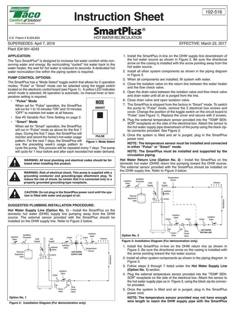
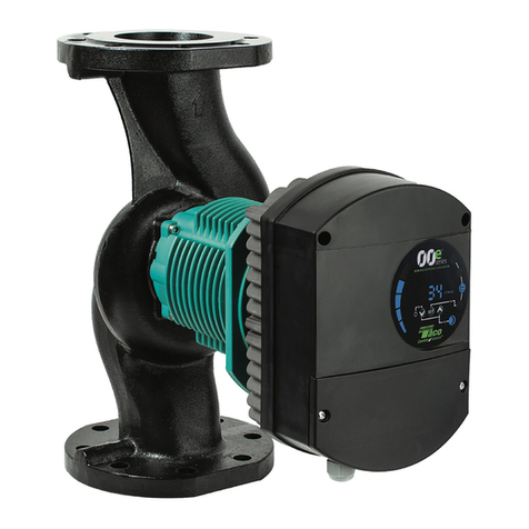
Taco 00-VS User manual

1
Instruction Sheet
Variable Speed - Setpoint (00-VS)
“00” and Load Match®Cartridge Circulators
102-143
SUPERSEDES: May 1, 2010 EFFECTIVE: October 1, 2010
Plant ID# 001-3811
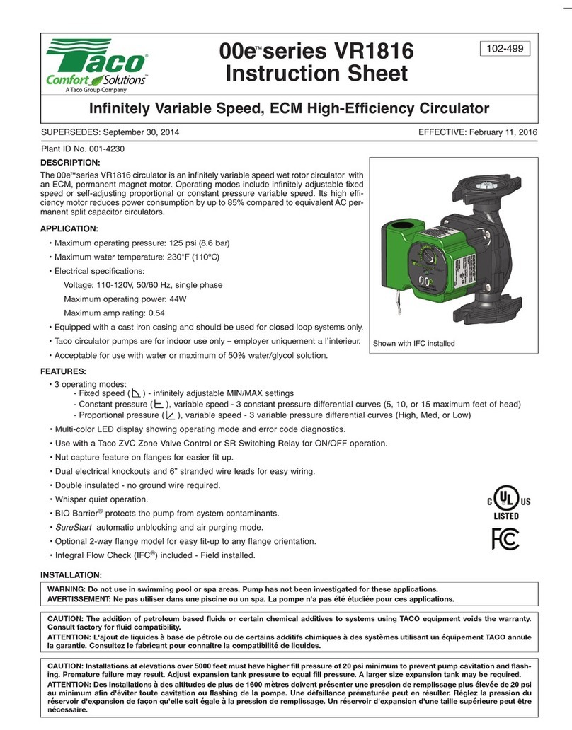
The Variable Speed - Setpoint “00” Cartridge Circulator (00-VS) is a microprocessor-based pump designed to regulate the tempera-
ture to a system through variable speed injection mixing. The 00-VS regulates the temperature to provide a fixed setpoint or a fixed
temperature difference (∆T) for heating or cooling applications. For fixed setpoint operation, a boiler return sensor can be connected
to protect the boiler against flue gas condensation.
In order to properly accomplish this mixing method, the following piping details should be considered.
Applications
The following are typical applications the 00-VS supports. The 00-VS includes a five DIP package with DIP siwtches 1, 3 and 5 used
to configure the control for a given application. These DIP switch configurations are indicated to the right of the application drawing.
DIP switch 2 is used to select the appropriate temperature range for the desired setpoint target. DIP switch 4 is used to select the
controls variable speed output response. It is recommended that a normal response (DIP 4 = Off) is used. This will aid in reducing
potential thermal expansion issues in a system. If it is desired for the control to achieve the setpoint or ∆T target quicker, a more
aggressive variable speed output response can be selected by setting DIP switch 4 to On.
The 00-VS adjusts the variable speed output to the fancoil pump P1 to maintain a setpoint discharge air temperature at the duct
sensor whenever a heat demand is present. While the control is operating to maintain the setpoint temperature, the variable speed
output is adjusted to ensure the boiler inlet temperature is above the boiler inlet minimum setpoint.
The 00-VS adjusts the variable speed output to the P1 pump to maintain a setpoint temperature at the supply sensor whenever
a heat demand is present. While the control is operating to maintain the setpoint temperature, the variable speed output is also
adjusted to ensure the boiler inlet temperature is above the boiler inlet minimum setpoint.
The 00-VS adjusts the variable speed output to the P1 pump to maintain at least a setpoint temperature at the boiler sensor (S3)
whenever a heat demand is present. The control adjusts the variable speed output towards zero speed as long as the temperature
is above the setpoint.
The 00-VS adjusts the variable speed output to the P1 pump to maintain at least a setpoint temperature at the boiler sensor
(S3) whenever a heat demand is present. The control adjusts the variable speed output towards full speed as long as the
temperature is above the setpoint. Note: This application illustrates variable flow conditions through the boiler. This con-
trol configuration should only be used with a heat source which is not flow sensitive, such as a high mass cast iron boiler.
Supply
Sensor
(S1 or S2)
Boiler
Sensor (S3)
P1
“00-VS” DIP 5 = Off (Linear Output Characteristic)
DIP 3 = Off (Direct Acting)
DIP 1 = Off (Setpoint Target)
OffOn
1 2 3 4 5
Boiler
Sensor (S3)
Duct
Sensor
(S1 or S2) P1
“00-VS” DIP 5 = On
(Equal Percentage Output Characteristic)
DIP 3 = Off (Direct Acting)
DIP 1 = Off (Setpoint Target)
OffOn
1 2 3 4 5
Boiler
Sensor (S3)
High Mass
Boiler
P1
“00-VS” DIP 5 = Off (Linear Output Characteristic)
DIP 3 = Off (Direct Acting)
DIP 1 = Off (Setpoint Target)
OffOn
1 2 3 4 5
Boiler
Sensor (S3)
P1
“00-VS”
DIP 5 = Off (Linear Output Characteristic)
DIP 3 = On (Reverse Acting)
DIP 1 = Off (Setpoint Target)
OffOn
1 2 3 4 5
00-VS-1
00-VS-3
00-VS-2
00-VS-4
A Taco resource – saving product

2
Supply
Sensor (S2)
Return
Sensor (S1)
P1
DIP 5 = Off (Linear Output Characteristic)
DIP 3 = Off (Direct Acting)
DIP 1 = On (∆T Target)
OffOn
1 2 3 4 5
“00-VS”
The 00-VS adjusts the variable speed output to the P1 pump to maintain a setpoint temperature difference (∆T) between the supply
sensor and the return sensor whenever a heat demand is present.
Supply
Sensor (S2)
Return
Sensor (S1)
Condensing
Boiler
P1
DIP 5 = Off (Linear Output Characteristic)
DIP 3 = On (Reverse Acting)
DIP 1 = On (∆T Target)
OffOn
1 2 3 4 5
“00-VS”
The 00-VS adjusts the variable speed output to the P1 pump to maintain a setpoint temperature difference (∆T) between the supply
sensor and the return sensor whenever a heat demand is present. This control configuration incorporates a minimum variable speed
output percentage during operation. Refer to Minimum Variable Speed Output under the ∆T Target section for selecting the available
minimum variable speed output percentages.
Supply
Sensor
(S1 or S2)
Cooling
Storage
Tank
P1
DIP 5 = Off (Linear Output Characteristic)
DIP 3 = On (Reverse Acting)
DIP 1 = Off (Setpoint Target)
OffOn
1 2 3 4 5
“00-VS”
The 00-VS adjusts the variable speed output to the P1 pump to maintain a setpoint temperature at the supply sensor whenever a
heat demand is present. This application is typical of radiant cooling system. It is important to note that the 00-VS does not consider
condensation control. Condensation prevention on surfaces must be controlled externally from the 00-VS control.
(Ts)
∆Ts
(Tb)
Tb = Boiler supply temperature
convectors and 10
°
F for radiant floor heating)
Ts = System supply temperature
∆Ts = System supply temperature (Typically 20
°
F for
Note 1
Fig. 1
Note 1
Note 2
Note 2
Note 3
Balancing
Valve
Note 3
00-VS
Injection Pump
When the injection pump is turned off, there must be no heat
transfer from the boiler loop to the system loop. In order to avoid
this unwanted heat transfer, primary/secondary piping tech-
niques are used as shown in figure 1.
This piping arrangement requires that the injection piping be at
least one pipe diameter smaller than the piping of the boiler and
system loops. There must be no more than 4 pipe diameters
between the tees in the boiler and system loops (Note 1), in
order to prevent ghost flow when the injection pump is off and
the system or boiler pump is on. Also, there must be at least 6
pipe diameters of straight pipe on either side of the tees (Note 2),
in order to prevent the momentum of water from the boiler and
system loops from pushing flow through the injection loop.
Finally, there should be a minimum of 1 foot drop in the injection
loop in order to create a thermal trap (Note 3) in order to prevent
convective heat transfer through the injection loop.
Variable Speed Injection Mixing
Variable Speed Injection Mixing uses a pump as a mixing device instead of a 2-way, 3-way or 4-way valve. The 00-VS injects hot water
from the boiler loop into the cooler system loop. The speed of the pump is modulated in order to inject different rates of hot water into
the cooler system return water. This allows for virtually any water temperature to be supplied to the heating system. Most boilers cannot
operate at low temperatures, therefore the 00-VS injection pump can be modulated back in order to prevent the boiler from operating at
cold temperatures.
Design Procedure
In order to properly size the pump, follow the design procedure below:
1) Determine the design operating temperatures of the system loop and boiler. (Ts and Tb from figure 1.)
2) Determine the flow rate and design temperature drop (∆T: Delta T) in the system loop. If one of these variables is unknown, use
Equation 1 or 2 to determine the other variable.
3) Compute Tb - Ts. Look up the flow rates on figure 2.
4) The design injection flow rate for direct injection is calculated in Equation 3. If the injection flow rate is greater than 40 US GPM, a
3-way or 4-way valve may be required.
00-VS-6
00-VS-5
00-VS-7

3
3
On Of
f
1
2
38
4
56
7
9
10
RANGE
Design Injection Flow Rate (US GPM) = System Flow Rate (US GPM) x Flow RatioEq. 3:
Eq. 1: System Flow Rate (US GPM) =
500 x ∆Ts (°F)
Design Heating Load (BTU/hr)
Eq. 2: ∆Ts (°F) =
500 x System Flow Rate (US GPM)
Design Heating Load (BTU/hr)
Tb - Ts (
°
F)
∆Ts (
°
F)
0.40
0.00
0.20
1.00
0.80
0.60
10 30 50
70
90
Fig. 2
10
15
20
25
Flow Ratio
20 40 60 80
0.10
0.30
0.50
0.70
Fig. 3
Nominal Pipe
Diameter (inches)
TACO
Pump
This table assumes there are 5 feet of pipe, 4 elbows, and 4 branch tees of the listed diameter.
Balancing valve is assumed to be a ball valve. The approximate Cv value is provided in order
to allow for proper balancing device. Valve characteristics may vary for the same size and type
of ball valve from manufacturer to manufacturer.
Balancing
Valve Cv
Balancing Valve
Position (% open)
Design Injection
Flow Rate (US GPM)
20
30
25
40 40 20012
0012
0010
0010
0010
0010
007
007
007
007
006
2
1
1
1
1.5
1
0.75
0.75
0.5
1.25
34.2
18.2
28.8
19.8
10.8
10.8
10.4
6.9
15
5.76
36
30
50
50
100
50
40
40
40
100
30
16
14
12
9
7
8
4
003
0.5
2.4
30
1.5
2003
0.5
4.5
40
3006
0.5
4.5
40
0.90
5) Decide whether or not to include a balancing valve in the injection piping. A balancing valve allows adjustment when the injection
pump is larger than needed. A balancing valve also provides the possibility of manual operation of the system by turning the injec-
tion pump fully on and adjusting the balancing valve to obtain the desired supply water temperature.
6) The injection pump size and model of Taco 00 pump to install can be looked up in figure 3. Do not oversize the injection system. If
the injection system is not able to provide enough heat, the boiler’s aquastat may be increased.
Sequence of Operation
Power up and Heat Request
Whenever the 00-VS is powered up, the green PWR LED turns on. The 00-VS starts operating once a heat request signal is present
at the Heat Request (Ht Req) terminals. A heat request signal may be provided by external end switches from zone valves or ZVC/SR
series zone controls, applying a dry contact closure or a powered 24 V (ac) signal across the Ht Req terminals. If end switches or
switching relays are not available, a jumper must be installed to provide a heat request. Once a heat request signal is present, the
green HEAT REQ LED turns on.
Mixing Operation
Once a heat request is present, the 00-VS operates to maintain a target temperature based on either a fixed
setpoint or a fixed temperature difference (∆T). The percent output (% OUT) LED flashes at different rates based
on the speed of the pump. The target temperature is set using the RANGE dial, where the numbers on the dial
correspond to the temperature ranges available in the applicable mode. Refer to the Setpoint and ∆T sections
for a listing of the temperature ranges available.
The operation of the 00-VS is based on either direct acting or reverse acting operation.
Direct Acting (DIP switch 3 = Off)
In direct acting operation, the 00-VS increases speed on a temperature decrease and decreases speed on a
temperature increase. Direct acting operation is typically used in heating applications.
Reverse Acting (DIP switch 3 = On)
In reverse acting operation, the 00-VS increases speed on a temperature increase and decreases speed on a
temperature decrease. Reverse acting operation is typically used in cooling applications.
3
On Of
f
Fast
Response
4
On Off
Normal
Response
4
On Of
f
Variable Speed Output Response
The 00-VS allows for adjustment to the response rate. The response rate is the speed at which
the 00-VS operates to achieve target temperature. The response adjustment is made through DIP
switch 4.
The normal response is typically used in applications where the temperature at the sensor being
controlled changes gradually during operation.
The fast response is typically used in applications where the temperature at the sensor being con-
trolled changes rapidly during operation.

4
Sensor installed DIP switch 2 = Off DIP switch 2 = On
Setpoint Range
S1 (A)
(C) (D)
(B)30 - 75ºF
120 - 165ºF 165 - 210ºF
75 - 120ºF
S2
30ºF
35
40 65
45
50 55
60
70
75ºF
SETPOINT (A)
SETPOINT (C)
SETPOINT (B)
SETPOINT (D)
120ºF
125
130 155
135
140 145
150
160
165ºF 165ºF
170
175 200
180
185 190
195
205
210ºF
75ºF
80
85 110
90
95 100
105
115
120ºF
Sensor installed DIP switch 2 = Off DIP switch 2 = On
Setpoint Range
S3 (B) (C)75 - 120ºF 120 - 165ºF 120ºF
125
130 155
135
140 145
150
160
165ºF
75ºF
80
85 110
90
95 100
105
115
120ºF
SETPOINT
(
B
)
SETPOINT
(
C
)
1
On Of
f
5°F
10
15 40
20
25 30
35
45
50°F
∆T
Output Characteristic
The 00-VS bases its output on a linear characteristic or an equal percentage characteristic. The
output characteristic adjustment is made through DIP switch 5.
1
On Of
f
0% 100%
100%
% of Flow
Equal Percentage
Heat Output
Terminal Unit Output
Desired
Output
Equal Percentage
Output
0% 100%
100%
% of Flow
Linear
Heat Output
Equal
Percentage
5
On Off
Linear
5
On Of
f
Linear Output (DIP switch 5 = Off)
The linear output characteristic assumes there is a linear rela-
tionship between percent of full flow of the pump and heat output
of the terminal unit. The linear output characteristic is typical of
applications in which the pump is injecting into a constant circu-
lating loop which includes the terminal unit.
Equal Percentage Output (DIP switch 5 = On)
The equal percentage output characteristic assumes there is non-
linear relationship between percent of full flow of the pump and
heat output of the terminal unit. In order to achieve the desired
linear output, the 00-VS provides an equal percentage output.
The equal percentage output characteristic is typical of applica-
tions in which the pump injects directly into the terminal unit.
Setpoint Target (DIP switch 1 = Off)
Once a heat request is present, the 00-VS operates to provide a fixed setpoint target at either the system sensor (S1)
or system sensor (S2) location. In this mode, the 00-VS uses the two sensors and DIP switch 2 in order to select dif-
ferent temperature ranges. Select from the four available temperature ranges listed in the table below, the tempera-
ture range in which the desired setpoint falls within. Then set the desired setpoint using the RANGE dial, where the
first and last temperatures from the selected temperature range corresponds to 1 and 10 respectively on the RANGE
dial, with the temperature increasing in 5ºF increments.
Note: Only one of the sensors (S1 or S2) can be connected in this mode of operation.
Boiler Protection
When either system sensor (S1) or system sensor (S2) is installed for setpoint operation, and the boiler return sensor (S3) is installed
on the return side of the boiler, the 00-VS can protect the boiler against flue gas condensation. When this sensor is installed, the 00-
VS monitors the boiler return temperature. If the boiler return temperature is less than 135ºF, the 00-VS turns on the reduced output
(RED OUT) LED and decreases the speed of the pump.
Note: Boiler protection is not available when configured for Setpoint Target operation and Reverse Acting mode.
Setpoint Operation as a Limit (Boiler Protection with only sensor S3 connected)
Once a heat request is present and only sensor S3 is installed for setpoint operation, the 00-VS operates to provide a limiting setpoint.
The 00-VS operates the variable speed output based on the mixing mode of operation. When configured for direct acting, the 00-VS
adjusts the variable speed output towards full speed as long as the temperature measured at sensor S3 is above the limiting setpoint.
When configured for reverse acting, the 00-VS adjusts the variable speed output towards zero speed as long as the temperature mea-
sured at sensor S3 is above the limiting setpoint.
DIP switch 2 is used to select the different temperature ranges. Select from the two available temperature ranges listed in the table
below, the temperature range in which the desired setpoint falls within. Then set the desired setpoint using the RANGE dial, where
the first and last temperatures from the selected temperature range corresponds to 1 and 10 respectively on the RANGE dial, with the
temperature increasing in 5ºF increments.
∆T Target (DIP switch 1 = On)
Once a heat request is present, the 00-VS operates to provide a fixed ∆T target between the
system sensor (S1) and the system sensor (S2). The S1 sensor is the system return sensor and
S2 is the system supply sensor. The fixed ∆T is set using the RANGE dial, where 5ºF and 50ºF
corresponds to 1 and 10 respectively on the RANGE dial, with the temperature increasing in
5ºF increments.
Note: The S3 sensor is not functional in this mode of operation.

5
WARNING: Wiring connections must be made in accordance with all applicable electrical codes.
CAUTION: To prevent electrical shock, disconnect electric power to system at main fuse or circuit breaker box until
installation is complete. When a service switch is installed, more than one disconnect switch may be
required to deenergize this device for servicing.
DIP switch 2 = Off DIP switch 2 = On
Minimum Variable Speed Output
DIP switch 5 = On 62%
18%
42%
8%
DIP switch 5 = Off
Minimum Variable Speed Output
When the 00-VS is configured for ∆T Target operation and
reverse acting mode, a minimum variable speed output is incor-
porated during operation. In this case the variable speed output
is adjusted between the selected minimum variable speed
output percentage and full output. Select from the four different
minimum variable speed output percentages in the table to the
side. The 00-VS also provides full output for 30 seconds when
the Heat Request appears, then resumes normal operation.
Note: Minimum variable speed output is not available when
configured for ∆T Target operation and Direct Acting Mode.
Exercising
During long periods of no operation, the 00-VS is designed to exercise for 10 seconds every 3 days of no operation in order to prevent
precipitate build-up in the pump. The % OUT LED turns on during the exercising function.
Powering the control
Insert the line voltage wires through the knockout of the enclosure and connect the live wire to the H terminal and the neutral wire to
the N terminal on the PC Board. Ensure that no power is present during this process.
Heat Request
The heat request signal may be provided by jumpering the heat request (HT Req) terminals or by applying 24 V (ac) to the HT Req ter-
minals. This signal may come from zone valve end switches, Taco ZVC/SR series zone controls, or thermostats. When a thermostat is
connected directly to the heat request terminals, use dry contact style. (i.e. mechanical, digital hard wired or digital battery operated)
Sensors
Do not apply power to these terminals as this will damage the PC Board. The wiring terminals for the sensors may be removed for
ease of installation.
Do not run the wires parallel to telephone or power cables. If the sensor wires are located in an area with strong sources of electro-
magnetic inter ference (EMI), shielded cable or twisted pair should be used or the wires can be run in a grounded metal conduit. If using
shielded cable, the shield wire should be connected to the Com terminal on the PC Board and not to earth ground.
System and Boiler Return Sensors
The sensors can be strapped directly to the pipe using a cable tie. Insulation should be placed around the sensor to reduce the effect
of air currents on the sensor measurement. The sensors should be placed downstream of a pump or after an elbow or similar fitting.
This is especially important if large diameter pipes are used because the thermal stratification within the pipe can result in erroneous
sensor readings. Proper sensor location requires that the fluid is thoroughly mixed within the pipe before it reaches the sensor.
If the system sensor is used to measure duct (air) temperature, the sensor should be mounted in such a manner that it measures the
average duct outlet temperature.
System Sensor (S1)
Connect the two wires from the system sensor (S1) directly into the Com and
Wiring and Sensor Installation
S2 terminals on the PC Board.
System Sensor (S2)
Connect the two wires from the system sensor (S2) directly into the Com
and S2 terminals on the PC Board.
Boiler Return Sensor (S3)
Connect the two wires from the boiler return sensor directly into the Com
and S3 terminals on the PC Board.

6
Temperature Resistance Temperature Resistance Temperature Resistance Temperature Resistance
°F °C °F °C °F °C °F °C
-30
-20
-10
0
10
20
30
40
50
60
70
80
90
100
110
120
130
140
150
160
170
180
190
200
-34
-29
-23
-18
-12
-7
-1
4
10
16
21
27
32
38
43
49
54
60
66
71
77
82
88
93
234,196
165,180
118,018
85,362
62,465
46,218
34,558
26,099
19,900
15,311
11,883
9,299
7,334
5,828
4,665
3,760
3,050
2,490
2,045
1,689
1,403
1,172
983
829
WARNING: Do not use in swimming pool or spa areas; pump has not been investigated for this application.
WARNING: In the event the retaining screws have been pulled out of the housing, DO NOT replace them.
Use of any other screw may short out the stator windings, creating a risk of electrical shock.
CAUTION: When installing electrical connections, do not apply mechanical loads to the capacitor box;
otherwise, retaining screws may be pulled out of the housing, making circulator unusable.
Troubleshooting
As in any troubleshooting procedure, it is important to isolate a problem as much as possible before proceeding. The error messages
greatly simplify troubleshooting of the 00-VS. When the 00-VS flashes an error message, identify the fault and follow standard testing
procedures to confirm the problem. If you suspect a wiring fault, return to the wiring section on this brochure and carefully check all
external wiring and wiring connections.
For your safety and protection of permanent damage to the microprocessor, the 00-VS includes a 2.5 A 250 V (ac) field replacable fuse.
Testing The Sensors
A good quality test meter capable of measuring up to 5,000 kΩ(1 kΩ= 1000 Ω) is required to measure the sensor resistance. In addi-
tion to this, the actual temperature must be measured with a good quality digital thermometer.
First measure the temperature using the thermometer and then measure the resistance of the sensor at the 00-VS. The wires from the
sensor must not be connected to the PC Board while this test is performed. The wiring terminals are easily removed by pulling them
from the PC Board. Using the chart below, estimate the temperature measured by the sensor. The sensor and thermometer readings
should be close. If the test meter reads a very high resistance, there may be a broken wire, a poor wiring connection or a defective
sensor. If the resistance is very low, the wiring may be shorted, there may be moisture in the sensor or the sensor may be defective.
To test for a defective sensor, measure the resistance directly at the sensor location.
LED LED Status 00-VS Status
PWR Solid Power On
HEAT REQ Solid Heat Request
% OUT Flash (Solid) Variable Speed Output (100% Speed)
RED OUT Solid Reduced Output (boiler protection activated)
HEAT REQ Flash System Sensor S1 Fault.
00-VS does not operate
RED OUT Flash System Sensor S2 Fault.
00-VS does not operate
HEAT REQ and RED OUT Flash Boiler Sensor S3 Fault.
00-VS does not provide boiler protection.
PWR, HEAT REQ and RED OUT Flash No sensors connected, or incompatible mode and sensor combination.
00-VS does not provide boiler protection.
Multi-Status LEDs
Application
1. Maximum operating pressure: 125 psi (862 kPa) on all “00” Series Circulators, 200 psi (1379 kPa) on all Load Match®
Circulators.
2. Maximum water temperature not to exceed nameplate rating.
3. Cast iron circulators are to be used for closed loop systems. Bronze circulators are to be used for open loop, fresh water, or potable
water systems.
4. Taco Cartridge circulator pumps are for indoor use only – employer uniquement a l´interieur.

7
Installation
1. Mounting position – Circulator must be mounted with the motor in a horizon-
tal position. It may be mounted vertically with the motor up, provided that the
system pressure is at least 20 psi (138 kPa).
2. Rotating body – Body has an arrow on the front that indicates direction of flow.
To rotate body, remove the four body bolts, rotate body and replace bolts.
Make sure that the junction box is NOT located underneath the circulator.
(The junction box must NOT be located in the 6 o’clock position, as viewed
from the motor end.)
3. Electrical connections – Observe all applicable codes when connecting to power supply. The motor is impedance protected, and
does not require overload protection.
The pump cannot run backwards.
4. Fill system with tap water – The system must be filled before operating the circulator. The bearings are water lubricated and should
not be allowed to operate dry. Filling the system will result in immediate lubrication of the bearings. It is always good practice to
flush a new system of foreign matter before starting the circulator.
5. Circulator operation – Operate the circulator for 5 minutes immediately after filling system to purge remaining air from the bearing
chamber. This is especially important when installing the circulator during the off-season.
Replacing Cartridge Assembly
1. Disconnect the electrical supply.
2. Reduce system pressure to 0 psi and allow system to return to room temperature. Isolate the circulator by closing the service valves
or draining the system.
3. Remove the body bolts and swing motor assembly away from the body.
4. Pull cartridge out of the motor housing.
5. Install replacement cartridge, making sure that the cover plate is between the cartridge flange and motor.
6. Make sure the replacement cartridge corresponds to the full circulator product number. A complete parts list is available from your
local plumbing supply wholesaler.
7. Reassemble the circulator using the new gasket and bolts supplied.
8. Follow the “Installation” procedure to start up the circulator.
Replacing Integral Flow Check (IFC) Assembly (if applicable)
1. Disconnect the electrical supply.
2. Reduce system pressure to 0 psi and allow system to return to room temperature. Isolate the circulator by closing the service valves
or draining the system.
3. Remove the body bolts and swing motor assembly away from the body.
4. Remove IFC, using needle nose pliers.
5. Install replacement IFC by pressing valve into casing until it is firmly seated.
6. Reassemble the circulator using the new gasket and bolts supplied.
7. Follow the “Installation” procedure to start up the circulator.
Replacing Circuit Board
1. Disconnect the electrical supply and all field wiring to the circuit board.
2. Unplug the 3-pin plastic connector that connects the motor to the circuit board.
3. Bend the lip of the capacitor base to ease the removal of the circuit board. Pull the circuit board up and out.
4. Reverse directions to install the new circuit board.
CAUTION: 1. The addition of petroleum based fluids or certain chemical additives to systems utilizing
TACO equipment voids the warranty.
2. Use supply wires suitable for 90°C.
CAUTION: Installations at higher elevations over 5000 feet must have higher fill pressure of 20 psi minimum to
prevent pump cavitation and flashing. Premature failure may result. Adjust expansion tank pressure to
equal fill pressure. A larger size expansion tank may be required.
ATTENTION: Employer des fils d´alimentation adequats pour 90°C.
WARNING: To avoid electrical shock, disconnect the power supply to the circulator and the main electrical unit.

8
LIMITED WARRANTY STATEMENT
Taco, Inc. will repair or replace without charge
(at the company’s option) any Taco 00 Series
circulator or circulator part which is proven
defective under normal use within three (3) years
from the date of manufacture.
In order to obtain service under this warranty, it
is the responsibility of the purchaser to promptly
notify the local Taco stocking distributor or Taco
in writing and promptly deliver the subject product
or part, delivery prepaid, to the stocking distrib-
utor. For assistance on warranty returns, the
purchaser may either contact the local Taco
stocking distributor or Taco. If the subject prod-
uct or part contains no defect as covered in this
warranty, the purchaser will be billed for parts
and labor charges in effect at time of factory
examination and repair.
Any Taco product or part not installed or operated
in conformity with Taco instructions or which
has been subject to misuse, misapplication, the
addition of petroleum-based fluids or certain
chemical additives to the systems, or other
abuse, will not be covered by this warranty.
If in doubt as to whether a particular substance
is suitable for use with a Taco product or part, or
for any application restrictions, consult the
applicable Taco instruction sheets or contact
Taco at (401-942-8000).
Taco reserves the right to provide replacement
products and parts which are substantially similar
in design and functionally equivalent to the
defective product or part. Taco reserves the right
to make changes in details of design, construc-
tion, or arrangement of materials of its products
without notification.
TACO OFFERS THIS WARRANTY IN LIEU OF
ALL OTHER EXPRESS WARRANTIES. ANY
WARRANTY IMPLIED BY LAW INCLUDING
WARRANTIES OF MERCHANTABILITY OR
FITNESS IS IN EFFECT ONLY FOR THE DURA-
TION OF THE EXPRESS WARRANTY SET
FORTH IN THE FIRST PARAGRAPH ABOVE.
THE ABOVE WARRANTIES ARE IN LIEU OF
ALL OTHER WARRANTIES, EXPRESS OR
STATUTORY, OR ANY OTHER WARRANTY
OBLIGATION ON THE PART OF TACO.
TACO WILL NOT BE LIABLE FOR ANY SPE-
CIAL, INCIDENTAL, INDIRECT OR CONSE-
QUENTIAL DAMAGES RESULTING FROM THE
USE OF ITS PRODUCTS OR ANY INCIDENTAL
COSTS OF REMOVING OR REPLACING
DEFECTIVE PRODUCTS.
This warranty gives the purchaser specific
rights, and the purchaser may have other rights
which vary from state to state. Some states do
not allow limitations on how long an implied
warranty lasts or on the exclusion of incidental
or consequential damages, so these limitations
or exclusions may not apply to you.
COMFORT MADE EASY®
TACO, INC., 1160 Cranston Street, Cranston, RI 02920 Telephone: (401) 942-8000 FAX: (401) 942-2360.
TACO (Canada), Ltd., 8450 Lawson Road, Unit #3, Milton, Ontario L9T 0J8. Telephone: 905/564-9422. FAX: 905/564-9436.
Visit our web site at: http://www.taco-hvac.com
Copyright 2010 TACO, Inc.
Portions Copyright 2003
tekmar Control Systems Ltd.
tekmar Control Systems Inc.
Printed in USA
Table of contents
Other Taco Water System manuals

Taco
Taco Viridian Delta-T User manual

Taco
Taco 1400 Series User manual

Taco
Taco 1400 Series User manual

Taco
Taco 1900e Series User manual

Taco
Taco SmartPlus User manual

Taco
Taco 007e-2 Series User manual

Taco
Taco 2400 Series User manual

Taco
Taco Hot-LinkPlus User manual

Taco
Taco 0026e User manual

Taco
Taco Comfort Solutions 1900e Series User manual
Popular Water System manuals by other brands

dosatron
dosatron D 25 F owner's manual

Katadyn
Katadyn Spectra Watermakers Catalina 340R Installation and operating manual

DAB
DAB S4 instruction manual

Oase
Oase Water Quintet Creative operating instructions

BIO-MICROBICS
BIO-MICROBICS MicroFAST 4.5 installation manual

Crystal Quest
Crystal Quest Water Cooler Installation and maintenance information