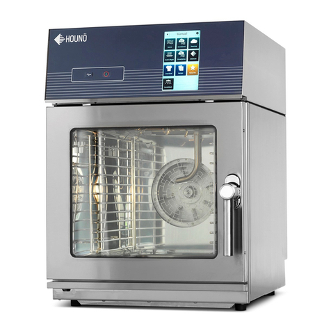
HOUNO B User manual

HOUNÖ
INSTALLATION MANUAL - English - ETL/1605
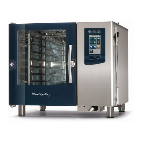
B, C, K, BPE, CPE & KPE Visual Cooking & CombiSlim Models
(Gas & Electric)
Software Version 1_3_4 11/2016
CAUTION: Read these instructions before installing the oven

2 INSTALLATION MANUAL
INTRODUCTION 5
LOCATING THE OVEN SERIAL
NUMBER
6
Type Plate of Electric Oven
6
Type Plate of Gas Oven
9
Type plate of CombiSlim Oven 6
Type Plate Information
7
IMPORTANT SAFETY
INFORMATION
8
UNPACKING AND INSTALATION
9
Unpacking and Installing the Oven
9
Weight and Dimensions 10
Installing the Oven
12
Clearance around the Oven
13
CONNECTION 16
Connection to Water Supply
16
Water Meter Setup 20
Connection to the Drain
25
Electrical Connections
28
Rinse Aid & Detergent Connection 34
Chemical Monitor Setup 35
Exhaust 38
GAS OVEN SAFETY PRECAUTIONS 40
Gas Leak Safety Measures
40
Safety Measurements for Gas Oven Installation
and Maintenance 41
Gas Hose Restraint 42
TOOLS FOR GAS ADJUSTMENT 44
GAS BURNER SETTINGS 46
TABLE OF CONTENTS

INSTALLATION MANUAL 3
FLUE GAS ANALYSIS 48
SmartTouch: Flue Gas Analysis Guid:e
48
Standard: Flue Gas Analysis Guide 50
HOUNÖ INSTALLATION CHECKLIST 52
HOUNÖ HANDOVER CHECKLIST 55
APPENDIX A 56
CombiWash – Water Usage
56
Maximum food load in kilograms (kg)
56
Noice level
56
IPX class 56
SERVICE AND REPAIR 57
Support
57
SAFETY 57
WARRANTY TERMS 58
TABLE OF CONTENTS
All installation must be carried out in compliance with local rules and
regulations.

4 INSTALLATION MANUAL
IMPORTANT
WARNING: Improper instal-
lation, adjustment, alterna-
tion, service or maintenance
can cause property damage,
injury or death. Read the
instllation, operation and
maintenance instructions
thoroughly before installing
or servicing this equipment.
INSTRUCTIONS TO BE FOL-
LOWED IN THE EVENT THE
USER SMELLS GAS MUST BE
POSTED IN A PROMINENT
LOCATION. This information
may be obtained by con-
tacting your local gas sup-
plier.
FOR YOUR SAFETY
Do not store or use gasoline
or other flammable vapors
or liquids in the vicinity of
this or any other appliance.
The information contained
in this manual is important
for the proper installation,
use, and maintenance of this
oven. Adherence to these
procedures and instructions
will result in satisfactory
baking results and long,
trouble free service. Please
read this manual carefully
and retain it for future refer-
ence.
ERRORS: Descriptive, typo-
graphic or pictorial errors
are subject to correction.
Specifications are subject
to change without notice.

INSTALLATION MANUAL 5
INTRODUCTION
Dear customer,
Thank you for choosing a HOUNÖ oven.
This manual contains the information required to install, connect and prepare the oven
properly for usage. Please comply with the guidelines in this manual. If these guidelines are
not complied with, HOUNÖ cannot be held responsible for any damage that occurs after
the oven has left the premises of HOUNÖ A/S. Please make the manual available to all
users of the product and retain it for future reference. The latest version of the manual can
be downloaded from www.houno.com.
Note that this document is subject to change without notice.
This manual is a step-by-step guide to installing the oven. At the top of each page is an
illustration marking how far along you are in the installation process.
For example, the first step out of 18 is marked at the top of this page. Therefore, this is the
start of the installation process. To ensure proper installation, we encourage you to read
the manual in its entirety and make sure you complete all the steps.

6 INSTALLATION MANUAL
LOCATING THE OVEN SERIAL NUMBER
When you order spare parts, additional equipment or request service for a Visual Cooking &
CombiSlim oven, you need the oven’s serial number,
You can find the serial number and type information on the right-hand corner post of the
oven and behind the front panel as shown in the following illustrations.
Type Plate of Electric Oven
Type Plate of Gas Oven
Type Plate of CombiSlim Oven of Electric Oven
113
6
32
4
5

INSTALLATION MANUAL 7
TYPE PLATE INFORMATION
Number Description
1 Year of production:
For example 12 = 2012
2 Month of production:
For example 05 = May
3 Identity number:
For example 4XXXX, 5XXXX, 6XXXX
4 Oven type and size:
For example C-Gas: Oven type C, Gas version
For example 1.06: 1/1 GN 6 shelves
5 Voltage:
For example 400V
6 Electrical diagram:
There is a copy located inside oven user panel (remove front panel),
and on Hounö’s home page: www.houno.com
7 Phase and frequency:
For example 1N: (1 phase with neutral), 3 (3 phase without neutral)
For example 50/60 Hz.: Hounö ovens can operate on both frequencies
8 Electrical consumption:
For example 9 kW (shows how much electricity the oven is using)
9 Gas types:
For example G20, G25, LPG 3BP/3P (G30/G31)
(dierent gas types available around the world)
10 Gas consumption:
For example 21kW (shows how much gas the oven is using)
11 Consumption:
For example 1,2 m3/h
12 Gas pressure:
For example 18-25mBar (shows optimal gas inlet pressure)
13 Water inlet pressure

8 INSTALLATION MANUAL
Utility Connections - Standards and Codes
THE INSTALLATION INSTRUCTIONS CONTAINED HEREIN ARE FOR THE USE OF QUALIFIED
INSTALLATION AND SERVICE PERSONNEL ONLY. INSTALLATION OR SERVICE BY OTHER
THAN QUALIFIED PERSONNEL MAY RESULT IN DAMAGE TO THE OVEN AND/OR INJURY TO
THE OPERATOR.
Qualified installation personnel are individuals, a firm, a corporation, or a company which
either in person or through a representative are engaged in, and responsible for:
• the installation or replacement of gas piping and the connection, installation, repair or
servicing of equipment.
• the installation of electrical wiring from the electric meter, main control box or service
outlet to the electric appliance.
Qualified installation personnel must be experienced in such work, familiar with all precau-
tions required, and have complied with all requirements of state or local authorities having
jurisdiction.
IMPORTANT SAFETY INFORMATION
The following icons are used throughout this manual to draw special attention to safety
related information.
The service personnel should observe and/or act according to the
information in order to obtain the best possible function of the
oven.
The service personnel must observe and/or act according to the
information in order to avoid any personal injury or damage to the
oven.
The service personnel must observe and/or act according to the
information in order to avoid any fatal injury. The symbol indicates
a hazard arising from dangerous voltage.

INSTALLATION MANUAL 9
UNPACKING AND INSTALATION
Before you begin the installation, check the oven for any transport damages. If there are
signs of damage, inform your supplier and freight company immediately.
UNPACKING AND INSTALLING THE OVEN
We recommend using a pallet trolley for lifting the oven. Some oven types must only be
lifted with a pallet trolley. If this is not possible, the right liftin tools are mandatory.
To Unpack and Move the Oven
1. Leave the oven packaging while moving the oven. Use a pallet trolley to move the
oven to the place in desired installation position.
2. Insert the forks under the lower cross tube of the stand and place wooden blocks
between the cross tube and the pallet trolley. You achieve the best possible
balance by introducing the forks from the front of the oven or from the motor side.
Ensure sucient clearance under the oven when you moving it from the pallet.
3. When you have placed the oven in position, you can remove the oven packaging.
However, leave the foil that covers the surfaces until you have installed the oven.
The foil protects the surfaces from sharp objects.
4. Remove the packaging from the racks inside the oven.
Disposal of Packaging Material
The packaging material must be destroyed in compliance with local rules and regulations.
You can request detailed information about the composition of the packaging material
from the HOUNÖ customer center.
Do not lift the oven from the left side.

10 INSTALLATION MANUAL
WEIGHT AND DIMENSIONS
Visual Cooking II Smart Edition oven weight
Oven Type VCIISE Weight (transportable without pallet)
1.06 155 kg – 341.7 lbs.
1.10 195 kg - 249.9 lbs
2.06 195 kg – 249.9 lbs
2.10 235 kg - 518.1 lbs
Oven Type VCIISE Weight (transportable only with pallet)
1.16 Roll-In 270 kg – 595.2 lbs.
1.20 Roll-In 305 kg – 672.4 lbs.
2.20 Roll-In 405 kg – 892.9 lbs.
CombiSlim II oven weight
Oven Type CSII Weight
23.06 57 kg - 125.6 lbs
1.06 67 kg - 147.7 lbs
1.10 81 kg - 178.5 lbs
Oven weight CombiPlus
Oven Type VCIISE Weight
1.06/1.06 300 kg – 662 lbs.
1.06/1.10 340 kg – 750 lbs.

INSTALLATION MANUAL 11
Visual Cooking II Smart Edition dimensions
Oven Type
VCIISE
Height with stand x width x depth*
millimeters
Height with stand x width x
depth*
inches
1.06 / 1.10 1492 x 899 x 831 mm 58.75 x 35.40 x 32.75 in
1.16 1592 x 899 x 831 mm 62.70 x 35.40 x 32.75 in
1.20 Roll-In 1852 x 899 x 831 mm 72.95 x 35.40 x 32.75 in
2.06 / 2.10 1492 x 1122 x 951 mm 58.75 x 44.20 x 37.45 in
2.20 Roll-In 1852 x 1122 x 951 mm 72.95 x 44.20 x 37.45 in
Oven Type
VCIISE
Height with stand x width x depth*
millimeters
Height with stand x width x
depth*
Inches
1.06/1.06 1800 x 900 x 970 mm 70.67 x 35.43 x 38.19 in
1.06/1.10 2030 x 970 x 900 mm 79.92 x 35.43 x 38.19 in
CombiSlim Oven Dimensions
Oven Type
CSII
Height with stand x width x depth*
millimeters
Height with stand x width x
depth*
inches
23.06 1565 x 513 x 631 mm 61.6x 20.1 x 24.8 in
1.06 1565 x 513 x 811 mm 61.6 x 20.1x 31.9 in
1.10 1765 x 513 x 811 mm 61.6 x 20.1 x 31.9 in
*Heights may vary depending on stand configuration
DEPTH
WIDTH
DEPTH
WIDTH
HEIGHT

12 INSTALLATION MANUAL
INSTALLING THE OVEN
The oven must be installed upright and levelled. These measuements must be read from
inside the oven cabinet, front and left side. You can adjust the position by using the
adjustment screws on the stand or on the legs of table models. You can also adjust the
installation height of the oven by using the same adjustment screws. This enables you to
adjust the installation height to fit the rack trolley.
Use a spirit level as illustrated to ensure that the oven is level.
Correct levelling
Incorrect levelling

INSTALLATION MANUAL 13
You level the stand by turning the adjustable feet.
Securing the oven
The oven sizes 1.16, 1.20 and 2.20 including roll-in versions of these sizes must be fixed to
the floor or wall by means of a mounting bracket.
CLEARANCE AROUND THE OVEN
Visual Cooking II Smart Edition
LOW Temperature Environment
At least 50 mm / 2 inches clearance from the rear and left side is
required. 70mm / 2.8 inches clearance to right side is required.

14 INSTALLATION MANUAL
HIGH Temperature Environment
At least 50 mm / 2 inches clearance from the rear and left side is
required. 400mm / 16 inches clearance to right side is required.
Do not place excessive heat sources such as hot plates, frying
pans, fryers and other sources of strong heat near the oven. The
minimum distance to such appliances must 400 mm.
Failure to comply may invalidate the oven warranty.
If the temperature on the right side of the oven is too high, a safety
shut down can occur.
If the oven is installed in a high temperature environment, It is highly
recommended that a heat shield is fitted to the right side of the oven to
prevent overheating.

INSTALLATION MANUAL 15
Heat shield
CombiSlim II
LOW + HIGH Temperature Environment
At least 50 mm / 2 inches clearance from the rear, left and right
sides is required.
100mm /4 inches clearance above the oven is required.
Do not place excessive heat sources such as hot plates, frying
pans, fryers and other sources of strong heat near the oven. The
minimum distance to such appliances must be 400 mm.
Failure to comply may invalidate the oven warranty.
If the temperature on the right side of the oven is too high, a safety
shut down can occur.
Number Equipment Oven Type
30200086 Heat shield 1.06
30200088 Heat shield 1.10
30200090 Heat shield 1.16
30200091 Heat shield 1.20
30200092 Heat shield 2.10
30200094 Heat shield 2.20

16 INSTALLATION MANUAL
CONNECTING
CONNECTING TO WATER SUPPLY
The Visual Cooking oven comes with two water connections by default. A special adapter is
provided so the oven can operate with a single water input. See below description.
Use an local legislation approved flexible connection hose to connect to the water supply.
Permanent water supply connections must be fitted with a stop tap.
Flush the tubes thoroughly before you connect the oven to the
water supply.
SUPPLY WATER SPECIFICATIONS
• Hardness of the water: max. 3 dH.
• Conductivity: min. 75 microsiemens.
• Minimum inlet water pressure: . 250 kPa (2.5 bar, 36 PSI) dynamic pressure when
using CombiWash.
• Maximum inlet water pressure: 600 kPa (6 bar, 87 PSI) dynamic pressure when
using CombiWash.
• Water flow: min 12 l/m.
• Water temperature: max 20°C (68°F).
• Chloride concentration mas. 100 mg/liter.
• Sulphate: max. 150 mg/liter.
• Chlorine: 0 parts per million.
• pH Factor: 7,0-8,0.
• If the water feeder is connected to the water supply with a flexible connection hose,
the hose should comply with local rules and regulations.
NOTE: Oven damage due to absence of a necessary HOUNÖ
PROTECT HydroShield water filter may render the warranty void.
NOTE: Oven damage due to lack of regular cleaning with HOUNÖ
PROTECT Detergent Intense and Rinse Aid may render the warranty
void.

INSTALLATION MANUAL 17
If the water temperature exceeds 20°C / 68°F, you may experience issues with
ClimaOptima calibration and cooling.
The warranty does not cover clogged up water filers or dirt in the solenoid valves.
To ensure that the water quality matches the requirements, we recommend that you
install a HOUNÖ PROTECT Hydro Shield water filter in the water supply line.
The water supply conection must be carried out by an authorized plumber in compliance
with local rules and regulations
Water that does not meet the specified requirements can damage the oven in form of
corrosion. Ovens damaged/corroded by water that does not meet the specification are
not covered by warranty.
HOUNÖ PROTECT Hydro Shield is available in three dierent filter sizes. The water filters can be
purchased directly at www.hounoshop.com.
WATER HARDNESS
HOUNÖ provides two dierent tools to meassure the hardness of the water.
TEST STRIPS:
Test procedure:
• Take a raw water sample, contain it in a sample cup or a similar sized container.
• Put the test strip in the raw water sample for approx. one second (make sure that all four
test zones are beneath the water surface).
• Shake o excess liquid from the strip.
• After one min the 0 to 4 of the test zones, will changes colour from green to red, indicading
the hardness of the supply water.
For external water meter use the matrix on page 25 to determine the filter size.
DROPLET TEST
Test procedure:
• Flush the vial and fill it with 10ml raw water.
• Add the test fluid one drop at the time.
• Count the drops until the colour changes from red to green.
• One drop = 1 DH.
For external water meter use the matrix on page 26 to determine the filter size.

18 INSTALLATION MANUAL
WATER SUPPLY LINES AND FILTERS
Oven located in areas where raw water have specifications do not require filtration. No
filter and only one supply line is needed.
For this non-filter option a manifold (1) is fitted to the two water inlet ports of the valves and
from the manifold directly to the water outlet of the kitchen.
Combislim oven have one water valve/inlet (1). This is for all water functions; wash, steam
and drain cooling. The hand shower is connected directly to the water supply with a T-fitting.
COMBISLIM II.
No filter
VISUAL COOKING II SE.
No filter.
VISUAL COOKING II SE COMBIPLUS.
No filter.
w
w
w
w
1
1

INSTALLATION MANUAL 19
COMBISLIM II
With Filter
Combislim oven have only one water inlet port for all functions.
When connecting a CombiPlus oven to the water supply, ensure that
you have separate water connections for the top and bottom oven.
Back side
INSTALLATION WITH WATER TREATMENT
Connections for oven installation in areas where the conditions of the raw water demands
a water filter; there is one connection for the steam generator and the jets in the oven
chamber. This connection must comply with local rules and regulations for water supplied
to household appliances. Water temperature must never be more than 20°C / 68°F. The
connection is located next the front of the oven (2). There is one connection for the hand
shower and drain cooling. The conections is the one closest to the back of the oven (1).
VISUAL COOKING II SE
With filter
VISUAL COOKING II SE COMBIPLUS
With filter
1
1
1
2
2
2
2
w

20 INSTALLATION MANUAL
WATER METER SETUP
VISUAL COOKING + COMBI SLIM
WATER METER SETUP FOR SMARTTOUCH OVENS
HOUNÖ ovens with SmartTouch display have a water meter build in the software.
The innovative software in HOUNÖ SmartTouch ovens works together with the HOUNÖ
PROTECT products to give you the best protection and lowest running cost. The oven mo-
nitors the consumption and tells you when to change detergent, rinse aid and water filter.
For this function to work as intented, the CPU need to be set up with the right water hard-
ness and filter size. Follow the below step-by-step description.
WATER METER SETUP
1. Switch on the oven by presing the on/o button.
2. In the main menu press the gearwheel in the upper righthand corner.
3. Select: Super user menu.
This manual suits for next models
5
Table of contents
Other HOUNO Oven manuals