Hoval MRHX-02N User manual

1
Manual OJ Electronics Stepper motor system
MRHX-2/-4/-8Nm & DRHX-1055, -1220
HO*-DRHX-1055/1220-MAD5
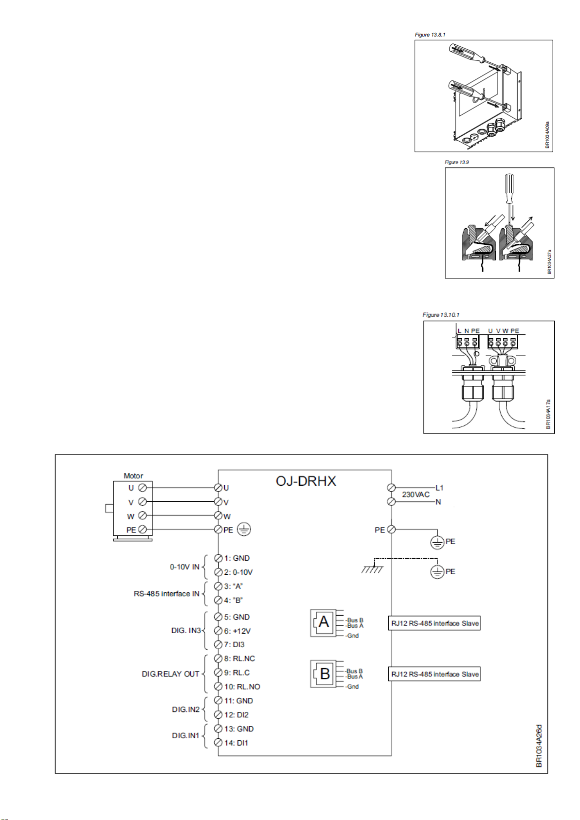
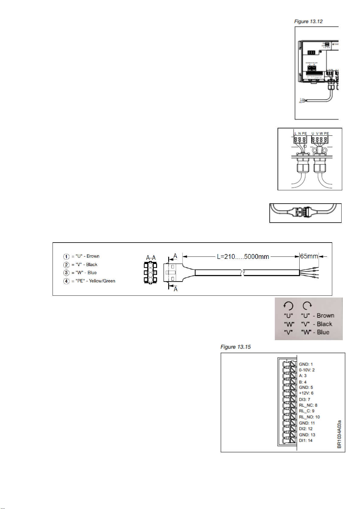
Hoval factory setting is for analogue use (0-10V)
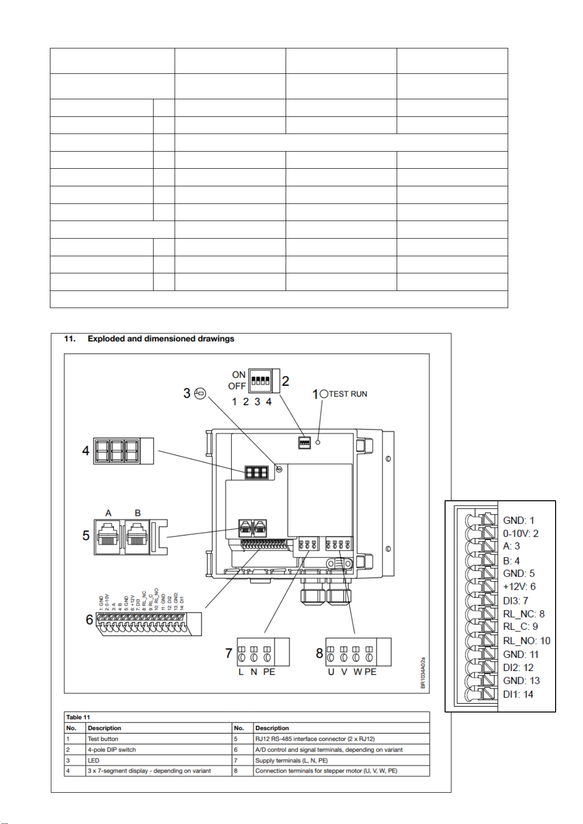
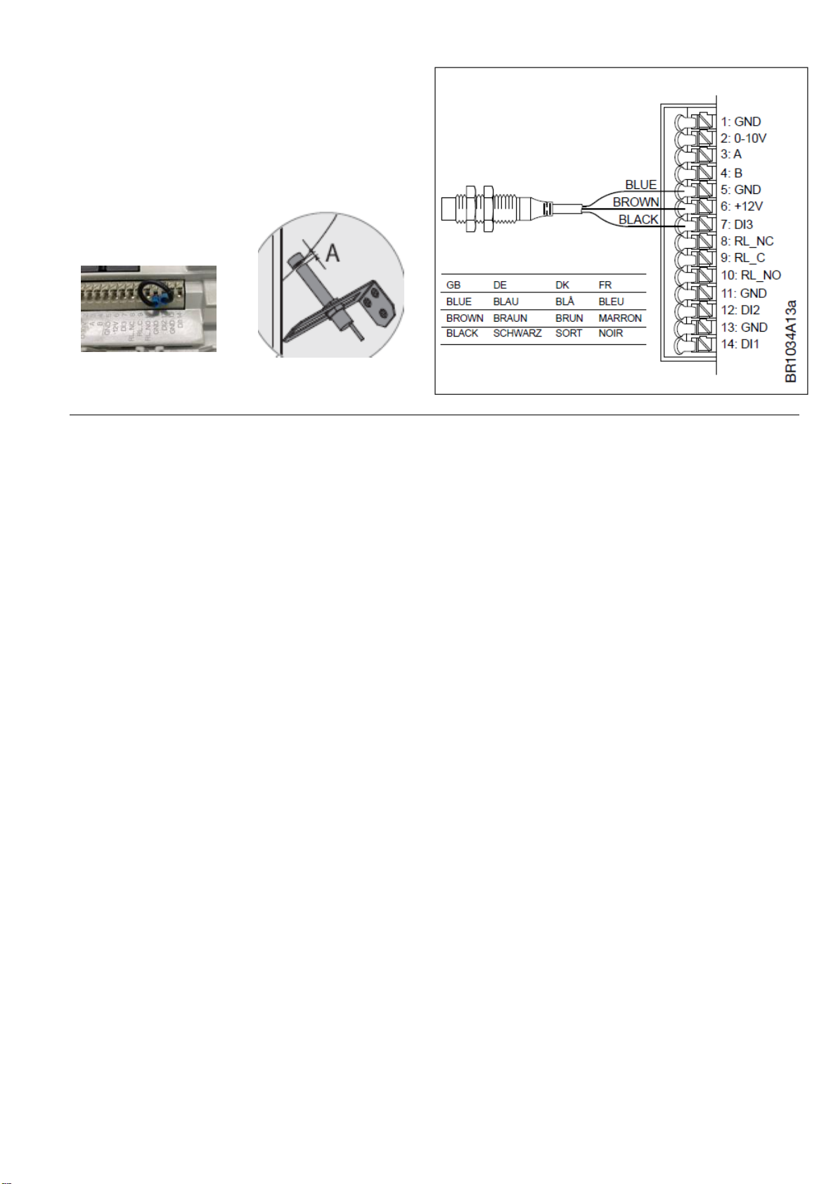
DI1: Rotor rotation
DI2: Enable external rotor guard
DI3: Signal from external rotor guard
MHRX = motor DRHX = control unit
*The DHRX control unit is programed with a Hoval custom made UDF file
This manual is specific for the setup of the Hoval drive system in RHE
For complete instructions, information, warnings (caution/ protection) see OJ's original manual.
Also valid for Modbus or OJ's DRHX PC –Tool (link and QR-code:
https://ojelectronics.com/hvac/products/oj-drhx-drives/
Introduction
MRHX/DRHX cannot be repaired on site. Never attempt to repair defective DRHX control unit or MHRX motor.
Contact Hoval for support.
Ensuring safety before installation
Product MRHX/ DRHX must only be installed by qualified personnel or people who have received appropriate
training and have thus become qualified to install the product.
Controller DRHX contains dangerous high voltage when connected to the mains. Mains voltage must always be dis-
connected before any installation, service or maintenance tasks are performed on the product.
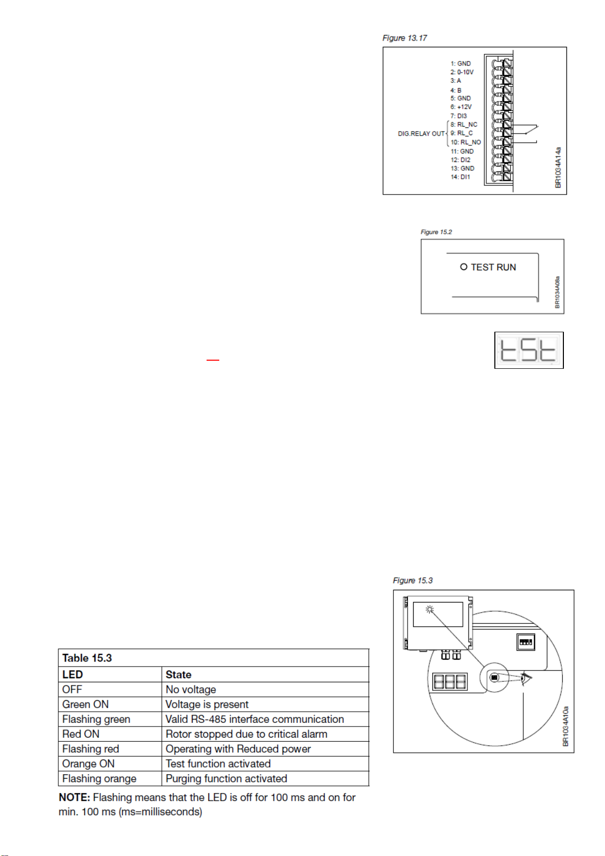
The test button can be operated while mains voltage is connected. The stepper motor/ rotor can be started up using
the test button, the 0–10 V input signal or via the RS-485 interface (Modbus).
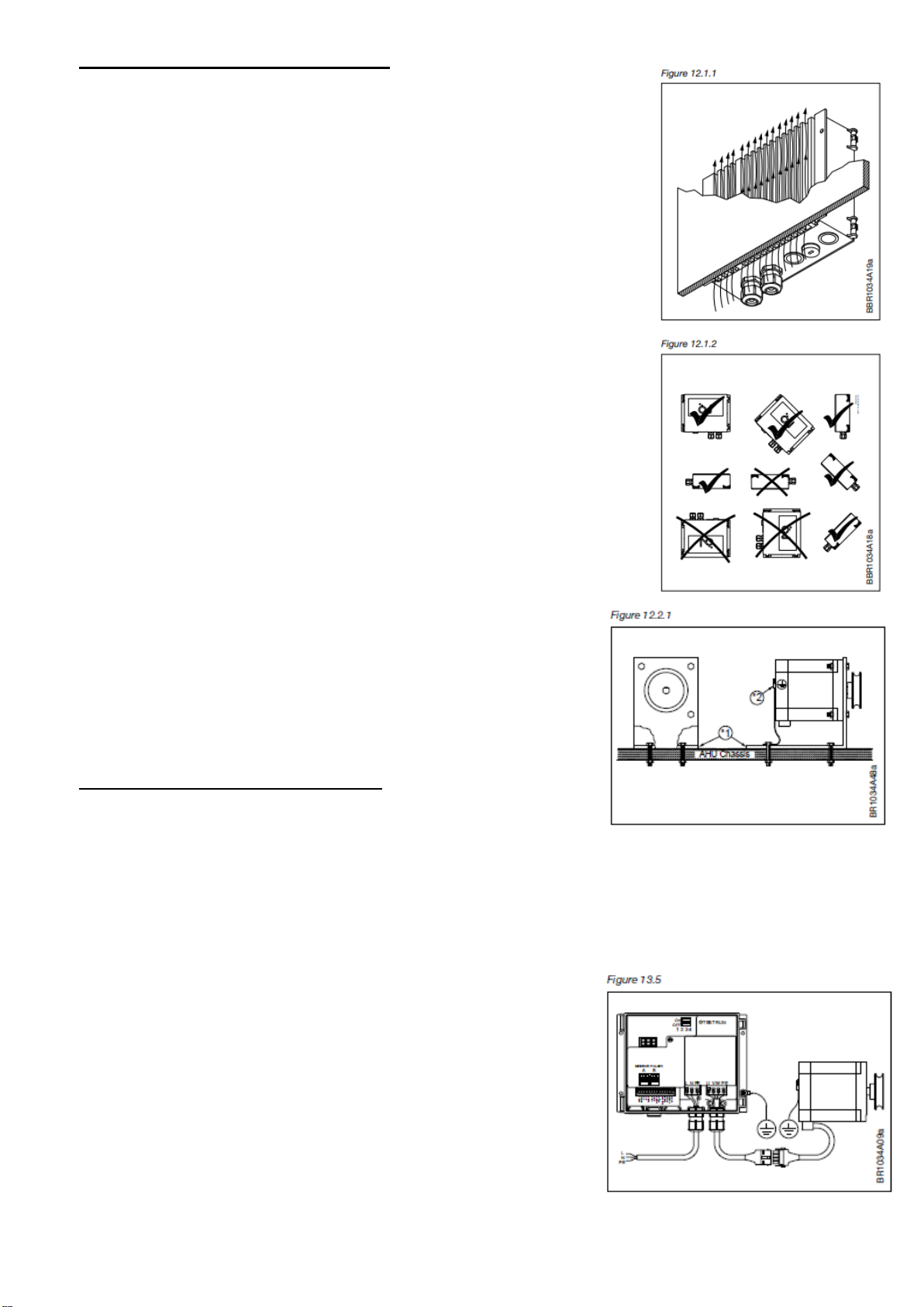
Before connecting mains voltage to the DRHX controller
- all components, i.e. stepper motor, belt, pulley and rotor, must be installed correctly.
- all openings, covers and cable glands must be properly fitted and closed.
To maintain the specified enclosure rating, unused cable glands should be replaced with blank glands/ plug.
Controller DRHX contains capacitors which become charged during operation. These capacitors can remain
charged even after the power supply has been cut off. There is a risk of severe personal injury if the
connection terminals or wire ends are touched before these capacitors have been completely discharged.
The discharge time is about 3 minutes under normal conditions.
Product use
DRHX controller is used to regulate the speed of a rotary heat exchanger in air handling units. Controller DRHX can
only be used to control MRHX stepper motor, supplied by OJ Electronics A/S. Never try to connect or control other
types of stepper motor.
Technical specifications
The controller and stepper motor is controlled by signals or commands from an external control unit in the AHU.
DRHX controller has built-in stepper motor protection and has a built-in EMC filter.
The product carries a manufacturer's warranty if installed in accordance with these instructions and applicable
installation regulations. If the product has been damaged (e.g. during transportation), it must be checked and (if
necessary) repaired by OJ Electronics A/S before the product is installed, connected to mains voltage and
energized.
No 4220637 Ver 3 2020-12-17/ SESTCH
Contact

2
Technical data
Motor MRHX-3P0xN-03C5
MRHX-02N
MRHX-04N
MRHX-08N*
Control unit
DRHX-1055 MAD5
DRHX-1220 MAD5
DRHX-1220 MAD5
Max Torque
Nm
2
4
8*
Input Signal
V
0-10
0-10
0-10
Output Rpm 50Hz
150 / 170 / 200 / 400* rpm
Voltage Input 50/60Hz
V
1x230
1x230
1x230
Motor voltage
V
3x0-200 V AC
3x0-200 V AC
3x0-200 V AC
Motor power
kW
0,055
0,110
0,220
Rated current
A
0,6
2,4
2,4
Class of protection
IP54
IP54
IP54
Weight motor
kg
2,4
3,5
5
Weight controller
kg
0,9
0,9
0,9
Shaft Ø (motor)
mm
12
12
12
*8 Nm torque at max. 250 motor rpm –but only max. 5 Nm torque at max. 400 motor rpm
6.

3
MECHANICAL INSTALLATION
Control unit
•To achieve correct cooling of the DRHX, it must always be positioned
so that there is free airflow around the cooling fins of the DRHX
(see fig. 12.1.1).
•To achieve the specified enclosure rating, the cable glands must not
point upwards (see fig. 12.1.2).
•To prevent water from entering the DRHX via cables and cable glands,
ensure that connection is performed in such a way that water is
prevented from accumulating around the cable in the gland.
•For optimal cooling of the DRHX, it must be installed vertical and on a
slope, with a max. gradient of 45° (see fig. 12.1.1).
The cooling fins on the reverse of the product should thus always be
able to be cooled by the natural thermic up flow past the cooling fins.
•DRHX must be installed on a flat solid surface.
•The product should be attached using at least 3 of the screw holes in
the aluminum cooler profile.
•The control unit should not be installed in direct sunlight.
Motor
•To ensure integrated rotor guard in the DRHX, and to avoid false
alarms and errors, it is important to install it proper. The stepper motor
comes with four holes for attachment to a solid mounting plate.
•The mounting plate must be firmly attached to the chassis of the
rotary heat exchanger or AHU (see figure 12.2.1, marked 1)
Do not use vibration dampers or springs!
Must be mounted on a fixed motor bracket.
ELECTRICAL INSTALLATION
Potential equalization
There is a risk of electrical interference if the ground potential between the DRHX and the air handling unit differ
from each other.
It's important to fix the control unit and the motor with metallic screws into the casing
If delivered mounted and fixed inside casing by Hoval above is fulfilled.
If not, following need to be insured of:
•Lugs should be used, and the equalization conductor should be
attached to the DRHX alu-profile via one of the screws used to
mechanically install the DRHX (see fig.13.5).
•Recommended cable cross section: 10 mm2.
•To prevent potential differences between system components, an
equalization conductor must always be fitted.
•A potential equalization connection must always be installed
between the stepper motor and the chassis of the air handling
unit (see section 12.2).

4
Opening the control unit
•Check that the voltage supply to the DRHX has been disconnected
before opening the cover.
•Wait approx. 3 minutes after disconnecting mains voltage before
removing the cover, warning see page 1.
•The controller can be opened using a screwdriver or similar (see
fig.13.8.1)
Spring terminals
•The connection terminals are spring-loaded and the stripped wire can
be easily inserted into the terminal by carefully pushing the wire into the
terminal without using tools.
Alternatively, the terminal spring can be loosened by pressing it
lightly with a screwdriver or similar implement. See fig. 13.9.
•Stripped wire ends or end sleeves must be between 8 and 10 mm.
•Wires can be removed by carefully loosening the terminal spring by pressing
lightly with a screwdriver or similar implement. See fig. 13.9.
Cable entries –cable glands
•The factory-fitted PG9 cable glands should be used when inserting power and
stepper motor cables into DRHX (see fig. 13.10.1).
•Remember to re-tighten the cable glands to ensure ingress protection.
Terminal and connector overview

5
Mains voltage connection
•The power supply is 230 V AC; +/-10%.
•The power cable is connected to the DRHX on the terminals marked ”L”, ”N” and ”PE”.
See fig. 13.12, or table 11 on page 2.
•It is recommended that the PE wire is 20 mm longer than the other wires in the cable.
If the cable is accidentally pulled out of the DRHX while there is voltage on the cable
and terminals, the PE wire will then be the last to be disconnected.
DRHX is thus prevented from causing electric shock.
•When the stripped wire is properly inserted into the terminal the terminal automatically
tensions.
•Remember to re-tighten the cable glands to ensure the ingress protection level
of the DRHX and to provide cable strain relief.
Cable
•Because the stepper motor cable from factory is directly connected into the motor
windings, it is not allowed to be replaced nor shortened.
•The motor cable is correctly assembled when the locking pawl on both sides of
the connector is locked in place with the connector from the cable from the DRHX
(extension cable).
•The connector can be separated again by releasing the locking pawl on both
sides of the connector on the motor cable and pulling the 2 connectors apart.
•The extension cable should be connected to the terminals marked:
U –Brown, V - Black, W –Blue, PE - Yellow/Green
•If rotation of rotor is wrong:
switch the "V" (black) and "W" (blue) cable to change motor direction.
Analogue/digital signal connections
•Connect A/D control signals to the terminal strip,
see fig. 13.15. 0-10V = terminal 1 + 2
•Max. wire dimension is 0.75 mm2 for control terminals.
•For further information on using the spring terminals,
see fig. 13.10.1
0-10 V control Which terminals!
•DRHX is factory-configured for 0-10 V control (this can
be changed Modbus operation*)
•The motor starts when there is a control signal over 1.1 V
(threshold value)
•The motor stops when control signal is less than 0.6 V
•The motor runs at maximum speed when there is a control signal over 9.5 V
*RS-485 interface control: DRHX can be controlled via Modbus or BACnet MSTP commands according to
the Modbus / BACnet MSTP protocols (see separate documentation on OJ Electronic homepage)

6
FUNCTIONS(power off when changing DIP switch setting)
DIP switch –settings and functions (are pre-set if delivered with a rotary heat exchanger from Hoval)
The DRHX series is equipped with 4 DIP switches for setting e.g. the stepper motor size and maximum motor speed
DIP 1-2: motor size / DIP 3-4: motor rpm (see table 15.1.1 and 15.1.2).
Required motor rpm is calculated by Hoval. Depends on rotor Ø, pulley Ø, rotor and motor torque, and given rotor
rpm. See table 15.1.3.
Table 15.1.3

7
Digital relay output
•DRHX is equipped with a digital relay output, which can for
example be used for alarm signals (see fig. 13.17).
•The relay output is a potential-free relay with changeover
switch.
•The factory-configured function is an alarm relay.
•Max. load is 2A/30 V DC/24 V AC.
•Terminals to use:
oAlarm signal: RL_C (9) and RL_NC (8)
oStart or Running signal: RL_C (9) and RL_NO (10)
(need to be changed via PC-Tool)
Test functions
DRHX series is provided with a test function in the form of a built-in test push-
button. The test button is located inside the controller in the upper right corner
and must be operated with the controller open (see figure 15.2).
The test button has different functions, depending on how long the button is
pressed in:
•Running Test for RHE
Belt should be mounted on rotor and pulley.
Start the test by pressing and continuously holding the test button. The controller will enter test mode.
Visible in display and LED will be orange. The test will remain active until the test button is released.
During this test run the motor will rotate with a maximum speed of 100 rpm.
Stop the test by releasing the test button. The DRHX will return to normal operation procedure and the
LED will turn green.
•Pulley calibration test see page 10
If drive equipment is wired by us from factory and mounted in a RHE this test have been done before
delivery.
Instructions on page 10. The pulley calibration test is made without the belt, rotor should not run.
LED indicator
DRHX series is fitted with an LED indicator, see fig. 15.3.
LED can be viewed both with open and closed cover.
For LED indicator codes see table 15.3:

8
Display
Display is visible with open and closed cover. The display shows current status for controller, stepper motor and if
rotor runs. See table 15.4. For alarm codes see table 19, page 11.
Rotation monitoring
Due to the stepper motor and rotor are mechanically connected through a belt, it is necessary to monitor whether
the rotor is rotating.
•If the motor is no longer turning the rotor due to a lack of tension or a broken/ damage belt, the DRHX
controller will trigger a “rotor guard” alarm (E01).
•The DRHX has two possibilities of rotor monitoring systems: internal and external.
•The factory setting is “Internal rotor guard”, external is an option (Hoval option RG3).
Internal rotor guard
The internal rotor guard monitors the rotation of the rotor by measuring the electronical signal returning from the
motor, will take place every 10 seconds.
•After five consecutive failed detections within 1 hour the alarm E01 is given (see page 11).
•The internal rotor monitor works automatically with a motor speed above 25 rpm.
External rotor guard
If external rotor guard is wired, “Internal rotor guard” will be automatically deactivated.
An external sensor (3 wired) can be connected to the digital input ports (Hoval product code/ option RG3).
See instructions on next page.

9
Mounting instruction for rotation guard, 3 wire (mtrl no 2045980):
•Connect the sensor to
5 (GND), 6 (+12V) and 7 (DI3)
•Connect a jumper between 11 and 12
to activate external sensor, is there to stay.
•Distance between magnet and senor:
A= 3-5 mm
Boost function
•The DRHX series has a built-in “Start function” which automatically allows higher current for the motor
during start-up (set to 10 seconds at 150% of rated current).
Purging function, cleaning
•When DRHX is controlled via 0-10 V signal (analogue), the purging/ cleaning function starts automatically
when the stepper motor has been stopped for 10 minutes.
•The stepper motor shaft will rotate 10 times at a low speed, after which the stepper motor will stop again.
Holding torque
•To prevent the rotor from rotating due to air flow going throw or start rotating by itself (can happen larger
rotor diameters, but it is very rare) the DRHX has a brake function which retains the rotor in a fixed position.
•This brake function is automatically activated when the motor has no operating signal.
Built-in protection
•If the temperature inside DRHX overstep 95°C, DRHX will attempt to reduce its internal heat generation by
reducing the amount of current that is sent to the stepper motor.
•DRHX has built-in current limitation for the protection of stepper motor and cables and can therefore not
supply more current than it is rated to (see technical data page 2).
•DRHX is short-circuit protected against phase-phase short-circuits on the DRHX connector terminals for the
stepper motor (U, V, W).
•DRHX control inputs are protected against short-circuits.
Display of actual speed
•During normal operation, the controller display will show the speed of the stepper motor.
Rotor blocked, do not run/ turn
If the load of the rotor is higher than the rated maximum torque of the DRHX system, the controller will trigger a
motor blocked alarm (E06)
•This detection depends on the tension of the belt and friction between belt and pulley (E01)
•Depending on the motor speed and the friction between belt and pulley, the DRHX controller will detect this
malfunction by observing the speed ripple of the motor and the vibrations of the system (E06).
oHigher ripple and vibrations will typically be detected at higher motor speeds, rpm.

10
Calibration test for pulley/ internal rotation guard STP in the display no 5??
- For example needed if received an E01 error/ alarm
If drive equipment is wired by us from factory and mounted in a RHE this test have been done before delivery
Before opening DRHX, the mains voltage must be disconnected for at least 3 minutes to ensure that there
Is no risk of dangerous residual currents in electronic circuits or capacitors.
The test button you find to the right of the DIP switches, see figure 15.2 on page 7.
1. Turn off the DRHX controller and remove the belt from the pulley.
2. Power up the DRHX controller and briefly press the test button, < 1 second, to start test mode
The LED will shine orange. Display will show "tSt" for test mode.
3. Wait for the stepper motor to reach maximum speed. It's limited to 100 rpm in this test.
4. After the stepper motor has reached the maximum speed, the system will start performing the internal rotor
guard function. The stepper motor will accelerate at short intervals every 10 seconds (that should be
possible to hear) for a minute.
5. If the stepper motor stops and restarts after one minute the internal rotor guard is correctly calibrated.
6. Press the test button for 2 seconds to end test mode. LED turn green. See point 8.
7. If the stepper motor continues to run for more than one minute, a recalibration needs to be done:
Recalibration:
Press and keep pressing the test button until LED flashes orange ( can take 10–50 sec).
Remove your finger from the button and the LED will turn green, the pulley/ internal rotor guard has been
calibrated.
8. After, turn off the DRHX controller and mount the belt. Start normal operation procedure.
Alarms and fault codes see table 19, page 10 and 19.1 page 11
DRHX has a built-in alarm monitor, which monitors optimal fault-free operation and triggers an alarm if operating
or performance problems are observed. Alarm codes can be read on the display. Alarms are either ”Critical” or ”Non-
critical” alarms: ”Critical” alarms stop the stepper motor. ”Non-critical” alarms reduce stepper motor performance.
•The built-in alarm monitor stops the DRHX.
•If the alarm situation passes, the alarm is automatically reset and DRHX will be restarted.
•If the maximum number of restarts (5 times/ 1 h) is overstepped, the alarm must be reset
•Alarm reset: The alarm is automatically reset if the power is disconnected for longer than 60 seconds.
or faul codes and alarm overview etc see table 19 and 19.1 in page 11
Remarks:
"C" = Critical alarm, stop the motor. / "NC" = Non-critical , reduce the motor performance.
”RP” = Reducing performance.
”SA5 ”= Stepper motor stops after 5 restarts caused by same fault within 60 min.
”S” = Stepper motor stops immediately

11
Before opening DRHX, the mains voltage must be disconnected for at least 3 minutes to ensure that there is no
risk of dangerous residual currents in electronic circuits or capacitors. If DRHX has no operating signal, but natural
drafts through the air handling unit cause the rotor and thus the stepper motor to rotate, there is a risk that the
stepper motor will induce voltage on the DRHX stepper motor terminals, making them dangerous to touch.
When servicing or troubleshooting the stepper motor: The stepper motor can become very hot >60°C.
Trouble shooting alarm codes
- also see page 10 and 12
Table 19.1
Alarm
Reason to alarm
Solution
E01
Belt is slipping (around the pulley) or broken
Tension/ replace the belt.
External rotation guard has been activated even though it
is not use (is a jumper placed between Digital input 2 +
GND, ground?). No rotation guard is wired to the DRHX.
Deactivate external rotor guard by
removing the jumper.
If external rotation guard is used: check if magnet/ sensor/
holder is loose or missing. Check so that sensor is in front
of the magnet and with correct distance (see page 9).
Fix magnet/ sensor/ holder to its position
Distance between sensor and magnet
should be 3-5 mm (see page 9)
Accidental calibration of the rotor and pulley by "double"
clicked when running the test function (page 7) or
forgetting to take the belt off before calibration test (page
10).
Make the test/ calibration again, see page
10.
If the motor is too powerful for the rotors load (large motor
to a very small load). The rotor torque is lower than the
internal rotor guards minimal torque limit for chosen type of
DRHX/ MRHX system (i.e spare part for old RHE).
Exchange type of MRHX motor and if
needed DRHX controller so its fits the
rotor type.
Contact Hoval for support.
E06
Wobbling belt. Could be caused by incorrect mounting,
damaged or out of shape rotor.
Correct and tension the belt.
Check installation for damage.
If needed, contact Hoval for support.
If springs or dampers are used with the motor bracket, the
vibrations can stop the MRHX motor, internal sensor will
be giving error (e.g. if use new spare part to old RHE).
Change to a fixed motor bracket (without
spring, dampers).
If the motor is under dimensioned (small motor to a large
rotor load), the motor will not be able to turn the rotor (i.e
new spare part for an old RHE)
Check if the correct size/ type of drive
equipment is mounted. If correct,
maintenance is needed, i.e adjust the
brush sealing (see manual for RHE).
If wrong drive equipment: exchange to
correct type/ size.
Check the pressure drop, air volumes (also difference
between the channels) and velocity.
See maximum values in Hoval handbook.
E09
Internal error between MOC (motor) and AOC (application):
Can be an update issue when installing new software
Try to re-install firmware again.
Contact Hoval for support.
If the error occurs by after the system has been running for
a period of time
Exchange the controller DRHX.
Contact Hoval for support.

12
Before opening DRHX, the mains voltage must be disconnected for at least 3 minutes to ensure that there is no risk of
dangerous residual currents in electronic circuits or capacitors. If DRHX has no operating signal, but natural drafts through the air
handling unit cause the rotor and thus the stepper motor to rotate, there is a risk that the stepper motor will induce voltage on the
DRHX stepper motor terminals, making them dangerous to touch.
When servicing or troubleshooting the stepper motor: The stepper motor can become very hot >60°C.
Troubleshooting - also see page 10/11, table 19 and 19.1 Fault and alarm codes
Troubleshooting when DRHX is controlled via A/D signals (0-10 V):
Symptom
Cause
Action
Stepper motor is not
running
Lacking supply voltage
Check the voltage supply (230 V AC) to DRHX terminals
”L” and ”N” (Nominal supply voltage is stated on the rating
plate). LED displays constant green light; see table 15.3 page 7
Check whether short-circuit protection has been activated,
external controller in the AHU.
Poor electrical connections
Check electrical connections. Make sure there are no loose
threads when connecting to the terminals, use cable shoes
(multi core).
Wrong stepper motor for DRHX
setup
Check that the DIP switch is correctly set for the selected
stepper motor size and speed.
Check that motor and controller fit: MRHX-2 = DRHX-1055,
MRHX-4, -8 = DRHX-1220
Lacking operating signal
A/D control: DRHX can be configured via the RS-485 interface register
to receive a start signal via an optional digital input. If this function is selected,
check that the DRHX has a signal connected to the "Start/Stop” input - digital
input Din 1, 2 or 3, depending on the configuration.
Lacking 0-10 V DC control signal
Check that DRHX receives an operating signal >1.1 V
on ”0-10 V In”.
Active alarm
Read active alarms via the display and remove what is causing
the alarm see page 11.
(can also be read by using DRHX-PC-Tool or via Modbus).
The stepper motor has been
stopped 5 times by the built-in
stepper motor protector because of
overloading or other alarm
Reset the alarm by disconnecting the power supply to DRHX
and reconnecting it after approx. 60 seconds.
Defective/ broken DRHX controller
Replace DRHX.
Never attempt to repair a defective DRHX controller.
Contact Hoval for support/ replacement/ repair.
Stepper motor is defective/ broken
Replace stepper motor.
Never repair a defective MRHX motor.
Contact Hoval for support/ replacement/ repair.
Stepper motor/ rotor
is running in wrong
direction
Wrong phase sequence in stepper
motor cable
Swap two phase wires in the controller DRHX. Switch the "V"
(black) and "W" (blue) cable to change motor direction (see
page 4)
DRHX cuts out due to
an alarm
Active alarm
Read active alarms via the display and remove what is causing
the alarm see page 11
(can also be read by using DRHX-PC-Tool or via Modbus).
The alarm is re-activated after reset
Repair the cause of repeated alarm activation, see page 11
The rotor stops
unintentionally
(Also see Fault code
E01 on page 11)
Internal rotor guard detects a loose
or defective belt
Tighten or replace belt
The internal rotor guard is
incorrectly calibrated
Make a re-calibration; see " Calibration test for pulley/
internal rotor guard" on page 10
External rotation guard.
/ External rotation guard is
activated even if it's not in use
See Fault code E01, page 11
This manual suits for next models
4
Table of contents
Popular Engine manuals by other brands

SIMONINI Racing
SIMONINI Racing VICTOR 1 manual

Evinrude
Evinrude E-TEC E115DPLSCR Service manual

Jacobsen
Jacobsen Ransomes MP493 Dealer's manual

Baumuller
Baumuller DSM1 Commissioning and Maintenance Instructions

Assun
Assun AM-CL2845MAN Series product manual

Generac Power Systems
Generac Power Systems GTV-990 manual