Howard Photofact Columbia 560 User manual

UI
ct
d,<
o
Hg
E'
==
o
TJ
PHoToFACT* Fold.t
REEL SIZE
5" (600 ft. )
?" (1200 ft. )
COTUMBIA RECORDS
,VIODEL 560, A
? |', sPEED
I hour
I 'houro
General lnformation
Columbia Models 560 and 560A are mechanically alike. The major difference between the
two models is in the head used. Model 560 uses a single unit record-erase head while model
560A uses a two unit record-erase head.
Models 560 and 560A are designed to record and play two tracks of material on standard
width recording tape. This doubles the recording and playing time without loss of quality or
frequency response. Recordings can be made from a phonograph, radio or television receiver,
in addition to those made directly from the microphone.
These recorders have two speeds, 3 3/ 4n and ? l/ 2', per second. Using both tracks, the
recording times are as follows:
fl
3P
FF
.s3
>g
UI
3 31 4" SPEED
I hour
2 hours
Models 560 and 560A are designed to operate on 60 cycle, ll0-120 volts, AC supply only"
Before connecting to a supply line, be absolutely certain. that it agrees with the above specifi-
cations.
Supplied by:
Columbia Records
799 Seventh Avenue
New York, N. Y.
ffris moferiol compiled ond published by
rw. sAts & co,, lNC., INDIANAPOlIS, INDIANA
Copyriglrt 1957 . Ail Rightt Rcocrvcd
$t'I 363
HOWATD
FOTDTR O

Figure I
Specifications
Fast Forward And Fast Re$/ind Speed :
5" Reel, (600 ft. ) l5 seconds (Approx. )
7" Reel,. (1200 ft. ) 105 seconds (Approx. )
Frequency Response:
3 3/ 4" speed - 65 to 6000 cycles per second
7 L/ 2" speed - 65 to 8500 cycles per second
Bias and Erase Frequency: bZ. b KC
Bias Voltage:
Shure Head, l0 volts bias
Michicgan Mag. Head, 20 volts bias
Power Output:
2 Watts undistorted
3 Watts maximum
Inputs:
Microphone, I meg. impedance
Radio-Phone, .5 meg. impedance
Outputs:
Two internal 5" speakers
External 3.2 ohm speaker
External-low impedance across 3.2 ohm voice
coil for external speaker.
External high impedance for external amplifier
or monitor in Record or Playback position.
Maximum Reel Size:
?" (1200 ft. )
Page 2
Operati ng I nstructions
Speed Control
The operating speed setting is accomplished by
placing the speed control button (I) in either the ilUpil
or 'Down" position. "IJp" for 3 3/ 4" per second and
'Down" for 7 l/ 2" pet second.
CAUTION: NEVER operate this control unless
the ON-OFF switch (12) is in the ON position.
Threading Tape
l. Place a reel of tape on the right reel plate
(9), and an empty reel on the left reel plate (9) making
certain the reel slots engage thepins on the reel plates.
2. Turn the H.ay-Record control knob (b) in the
center of the machine to the fully counterclock-wise
position.
3. Unwind about I0" of tape from the reel" Hold
a section of the tape straight with both hands and insert
the tape in the tape slot making certain that the dull
coated side faces the rear of the recorder"
4. Insertthe end ofthe tape intooneof thethree
radial slots in hub of the tape-up reel. Turn the reel
several turns, clockwise, until the tape is secured to
the reel and all slack is taken up between the reels.
To Record From Microphone
nby rotating the "Tone,,
control to the right. Allow about 30 seconds for the
tubes to warm up.
2. Insert the microphone plug into the "Mike"
iack" 3. Adjusi the speed control knob (1) for the de-
sired speed - 3 3/ 4" or 7 l/ 2" per second.
4. Push down on the Play-Record control knob

1
(5) as faras it willgo. Hold knobdownand turnclock-
wise until it locks"
5. Hold the microphone away from your mouth
about 6 tb 12 inches and speat in a normal voice. DO
NOT SHOUT. Adjust the volume control until the re-
cord level indicator flashes on the loudest sounds.
Note: Correctvolumelevelonrecording isvery
important. Too weak a signal, which does not cause
flashing on the recording level indicator, will result
in weak playback and high background noise. Too strong
a signal, which causes continuous flashingof the level
indicator, will result in distortion during playback.
To Record From Radio:
Recordings from a radio may be made by one of
these methods.
1. Through the microphone by pickup from the radio
speaker:
Place the microphone about 6" to 12" in front of
the radio speaker. Turn the radio volume control to
a normal level. Setting it too high will cause distortion.
Turn the radio tone control to treble or high. Set the
recording level andrecord as under "ToRecord From
Microphone".
2. Though a direct connection to the Radio speaker;
Make up a shielded cable with a two conductor
phone plug on one end and two alligator clips on the
other end. Connect the alligator clips across the voice
coil terminals of the radio speaker and insert the plug
into the "Radio-Phono" jack. Set the radio volume
and tone controls as described above. Set the recording
level and proceed as described under I'To Record From
Microphone".
3. Through a direct connection to the volume control
of the radio:
Make up a shielded cable with a two conductor
phone plug on one end. Connect the other end across
the radio volume control. Insert the phoneplug in the
"Radio-Phono" jack. Set the recording level andpro-
ceed as described under "To Record from Microphonetl
The radio volume and tone controls do not alfect this
set up, consequently they may be set any place.
To Regorl From Record Player
1" If the Record Player being used has a phone
type plug on the pick-up Leads, insert it into the I'Radio-
Phono" Jack. Set the recording level and proceed as
listed under "To Record From Microphone'r.
2. If the Record Player has astandard pin type
plug, which is mor'e common, an adapter is needed.
Insert the pin plug into the adapter and plug the adapter
into the "Radio-Phono" jack.
To Record From Television Receiver
Use one of the three methods described under
"To Record From Radio".
Dual Track Recording
This recorderis designed to record and play on
one-half the width of the tape at a time; thereby re-
sulting in twotrack recording. Torecord on theother
half of the tape remove the full reel from the takeup
(left) side, turn reeloverandplace iton thefeed(right)
side. In playing or recording you may stop any place
and reverse the reels to use the other track.
Fast Forward And Fast Rewind
High speed forward or rewind operation may be
obtained by pressing the degired knob (13) toward the
head cover. This wiU wind the tape on the desired
reel at a high speed aslong as the knob is held in this
position.
NOTE: Do not attempt fast forward or rewind
operation with the Play-Record control on any setting
except neutral position, as damage to the unit or tearing
of t}te tape will result.
Braling
This recorder contains an automatic brake mech-
anism giving moreaccurate tape control. To stop the
tape at any time, when operating on fast forward or
fast rewind, simply release the forward or rewind
control. The tape will automatically come to a stop.
1o Play A Recording
1. Thread the tape as described under rThread-
ing Tape".
2. Turn play-recordcontrol (5) clockwisewith-
out depressing until it locks"
3. Adjust the "Volurne" and'ofonet'controls (12)
to desired listening level.
To Use An External Speaker
Plug external speaker through a three conductor
plug into the "Output Jack". Connect the three con-
ductor plug as shown in sketch.
Tip - No Conuection
Caution: Donot insert plug into recorder with-
out external speaker attached.
To Use An External Amplifier
Plug the external amplifier into the [Output Jackfl
through a two conductor plug connected as shown in
sketch
To Edit And Splice Tape
NOTE: Since it is impossible toedit and splice
one trackwithout affecting the other, recordings to be
edited should be limited to one track only.
1. Tape may be edited by cutting out unwanted
portions, or by joining selections into another se-
quence. Announcements can be inserted between selec-
tions, etc. Unused tape can be spliced for re-use.
2. For best results cut tape at a slight diagonal,
joining ends togetherwith a butt joint and fastening on
the glossy side with splicing tape. Trim off any ex-
cessive width.
In the record position any recording on the tape
is automatically erased before the new recording is
put on the tape. Should it be desired to erase a re-
cording without recording new material, follow the
normal recording procedure, except set the volume
control to the full counter-clockwise position.
..l
=P
9;
F>-
tt
q*
.-fl o
>-
E'
l,l
Conn. one end
Connect one lead to ring To 3.2 ohm
Connect to
Page 3

Adjustments
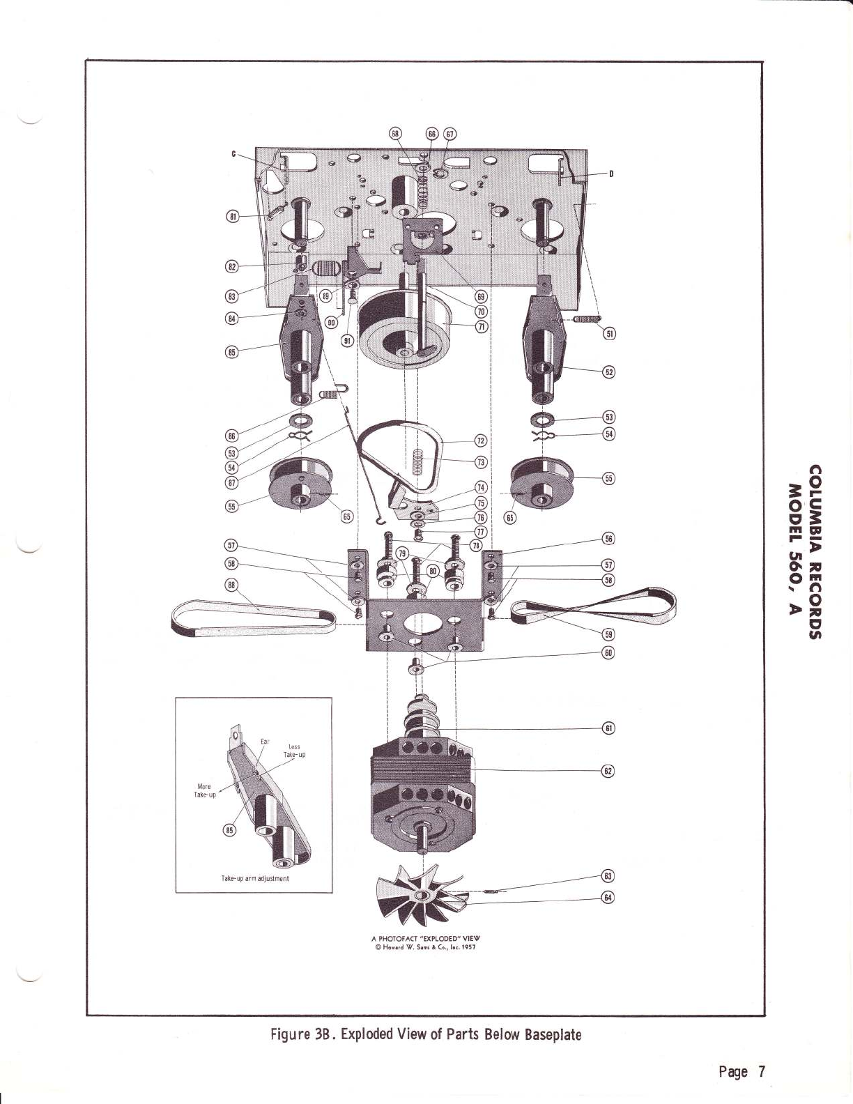
Spindle (19 and 48) End Play Adjustment
The spindles should have from l/ 32,, to l/16'rof
up and down movement. To adjust loosen set screw
(65) on spindle to be adjusted andmove the pulley (bb)
up or down as required until the correct end play is
obtained.
Take-Up Lever Adjustment
Spring (83) on take-up lever (90) controls the
timingof the left take-up reelholder (9). Withthe con-
trol knob (5) in the play back position, thetake-up reel
shouldstart revolvingat the sametime ora littleafter
the Pressure Roller (43) starts pulling the tape past
the head (39).
Check adjustment by placing a fully loaded ?',
reel on the take-up spindle. Rewind for about 10 se-
conds. Move the control knob (5) to the playback
position and observe the action described above.
If adjustment is required, bend ear on take-up
arm (85) iu the position and direction indicated in
sketch on exposed view. Caremustbeexercised when
making this adjustment and repeated trials between
bends should be made.
Take-Up And Feed Reel Drag
When the control knob (5) is placed in the INeu_
tral" position the reels should stop prompuy with a
minimum of overrun. Thereshould benoloopingof the
tape. With control knob (5) in the neutral position and
without reels on theholders, they mayrevolve slightly,
butonce the reels are put in place they should not re-
volve.
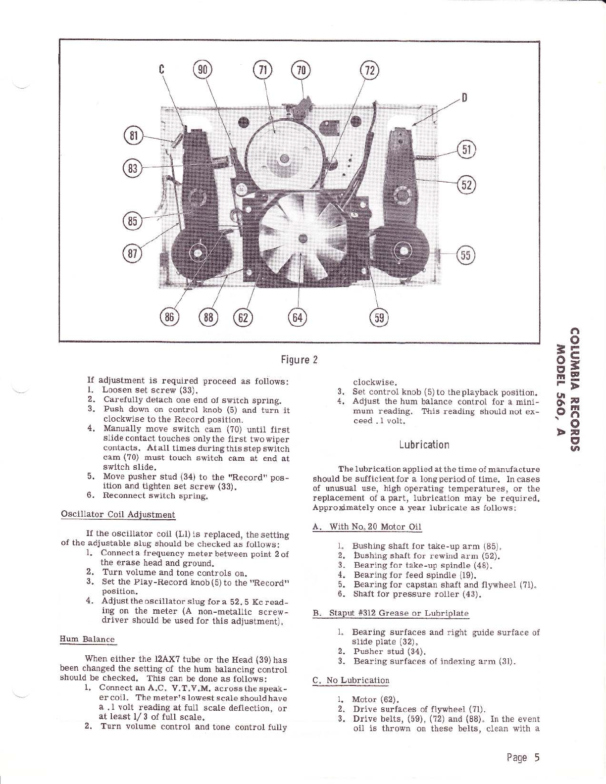
Stops, labeled "C" and 'T)" on figure 2, located
on base plate (22) controls the above action. Theyre-
gulate the amount of return that take-up arm (85) or
rewind arm (52) makes after controls have been re-
leasedl not sufficient return would cause continued
Fast Rewind or Fast Forward operation, while too
much return would not allow drive belts (88) or (59) to
put a drag on the respective pulleys. Bend these stops
carefully so as to obtain operation described above.
Stop "C"controls the take-up sidewhile stop tDrtcon-
trols the rewind side.
Head Alignment Adjustment
It is extremely important that the Head (39) be
lined up perfectly with the tape. If not the result will
probably be low output, track overlap, or loss of high
frequencies.
l. Model 560 (SHURE Head)
If the SHURE Head requires replacement the
complete assembly composed of the head and head
holder should be replaced" The head holder is adjusted
individuallvto thehead and sealedatthefactory. When
installing head ( 39A) observe the following precautions:
HEAD HEIGITT: Place a .l?9" gauge (between
11/64" and 3/16") near the mounting bracket and between
base plate (22) and bottom of head holder. Push down
on head (39A) and tighten set screw (23). Remove
gauge.
An alternate method ofadjusting the head height
when a gauge is not available follows:
Page 4
Remove the pressure shoe assembly (36)
from the pressure bracket so the head can
be observed through theopeningin thepres-
sure bracket"
Align head (39A) so the bottom of the head
opening is at the same level (or slightly high-
er) as the correspondingbottom of the open-
ing of the pressure bracket.
With the unit pulling tape, the tape should
approach the take-up reel nearly centered
between the flanges of the reel. If the tape
runs against the bottom flange it is an in-
dication that the head is too low.
Make "Output Response" adjustment as de-
scribed in Section 3 below.
2" Model 56OA /Michionn Mrqnctin F{cad\
On units using the Michigan Magnetic Head a
simpl.e alignment procedure is as follows:
a). Place a full reel of tape on the right hand
spindle(19) andthread tape. See "Threading
TaPe".
b). Pull tape tightagainst Heads (26) and(28) by
rotating one reel while holding the other reel.
c). Both heads should then be positioned so the
top edge of the tape is exactly even with the
bottom edge of the ground down 'tlat" section
on the face of the heads.
d). When in thisposition both heads shouldalso
be perpendicular to the bracket vertically
and horizontally.
e). The faces of the heads should be j.n line with
each other soas to present a flatsurface to
the tape, i. e. one head should not protrude
further forward than the other"
3. Output Besponse
To make this adjustment a tape on which a 3000
cycle note has been recorded by a unit known to be in
good operating condition will be required.
Connect an output meter, or AC voltmeter,
aeross the spealer voice coil of theunittobe adjusted.
While playingback the 3000cyclenote tape, pivot head
(39) back and forth on mounting screw (23) until maxi-
mum amplitude on output meter is achieved. Make
certain that head height has not been changed.
If a 3000 cycle tape cannot be make, use a re-
cording with hlgh note content to make the adjustment
described above.
4. Track Overlap
This should be checked by first making a re-
cording on a blank tape with the unit being checked.
Do notrewind thetape, merelyreverse thereels
and play back the other track.
There should be no sound but, if what is heard
isbackwards, there is trackoverlap. Tocorrect this,
it will be necessary to adjust the tape guide on the side
of the head holder by bending it upwards. This should
move the tracks further apart.
Switch Cam Adjustment
The Play-Record Switchin the amplifier chassis
is normally held inthe playpositionby aspringlocated
on the switch arm. Whencam onthe endof thecontrol
shaft (70) actuates switch, it should move the switch
far enough to allow all circuits to be switched from
Playback to Record.
a).
b).
c).
d).

Figure 2
fi
o
2r-
a--
aL
HE
np
.gn
.o
DN
I
gl
If adjustment is required proceed as follows:
1. Loosen set screw (33).
2. Carefully detach one end of switch spring.
3. Push down on control knob (b) and turn it
clockwise to the Record position.
4. Manually move switch cam (?0) until first
slide contact touches only the first two wiper
contacts. At all times during this step switch
cam (?0) must touch switch cam at end at
switch slide.
5. Move pusher stud (34) to the "Record" pos-
ition and tighten set screw (33).
6. Reconnect switch spring.
Oscillator Coil Adjustment
If the oscillator coil (Ll) is replaced, the setting
of the adjustable slug should be checked as follows:
l. Connect a frequency meter between point 2 of
the erase head and ground.
2. Turn volume and tone controls on.
3. Set the Play-Record knob(b)to the "Recordil
position.
4. Adjust the oscillator slug for a 52. b Kc read-
ing on the meter (A non-metallic screw-
driver should be used for this adjustment).
Hum Balance
When either the 12AX? tube or the Head (39) has
been changed the setting of the hum balancing control
should be checked. This can be done as follows:
I. Connect an A.C" V.T.V.M. acrossthespeak-
er coil. The meter's lowest scale should have
a .1 volt reading at full scale deflection, or
at least L/ 3 ot full scale.
2. Turn volume control and tone control fulty
clockwise.
3. Set control knob (5) to theplayback position.
4. Adjust the hum balance control for a mini-
mum reading. This reading should not ex-
ceed . I volt.
Lubrication
The lubrication applied at the time of manufacture
should be sufficientfor a longperiodof time. Incases
of unusual use, high operating temperatures, or the
replacement of a part, lubrication may be required.
Approximately once a year lubricate as follows:
A. With No.20 Motor Oil
1" Bushing shaft for take-up arm (85).
2. Bushing shaft for rewind arm (52).
3. Bearing for take-up spindle (48).
4. Bearing for feed spindle (19).
5. Bearing for capstan shaft and flywheel (?1).
6. Shaft for pressure roller (43).
B. Staput #312 Grease or Lubriplate
1" Bearing surfaces and right guide surface of
slide plate (32)"
2. Pusher stud (34).
3. Bearing surfaces of indexing arm (31).
C" No Lubrication
Motor (62).
Drive surfaces of flywheel (?1).
Drive belts, (59), (72) and (88). In the event
oil is thrown on these belts, clean with a
1.
2.
3.
Page 5

Frtd
O
Q.
ffi
Figu re 3A. Exploded view of Parts Above Baseplate
t-
Page 6

Take-up arm adjustmenl
A PHOTOFACT "EXPLODED" VIEV
@ Howcrd V. Srms & Co., lnc. 1957
Figu re 38 . Exploded View of Parts Below Baseplate
fi
o
F
C
=
g
7
rn
fi
o
7
C'
la
=
o
E
lr|
F
gt
o\
o
\
Page 7

petroleum solvent.
Do Not Use Carbon-Tetrachloide.
TROUBLES
Improper Tape Tal<e-up
1. Spindle (48) binding.
a). Lubricate and check end play. See ad-
justment section "Spindle End play""
2" Improper take-up spring (83) action.
a). See "Take-up Lever Adjustment".
3" Drive belt slipping.
a). Clean pulleys.
4. Broken drive belt.
a). Replace belts. Check adjustments
"Takeup Lever Adjustment" and 'rTak+
up and Feed Reel Dragr'.
Fails to Fast Forward properly
l. See above except for step 2.
(a) See eorresponding remedies above.
Fails to Fast Rewind Properly
l. See above except for step 2.
(a) See corresponding remedies above.
CAUTION: When replacing drive belt
(59) be sure to give it a half-twist.
Stalling or Binding
1. Speed control (1) setting changed while unit
not turned on. This should be done only while
motor (62) is rotating.
a). With motor (62) turned on try moving
Speed Control (l) up and down several
times.
b). Should the above fail, try holding Fast
Forward Control to the leftas far as it
will go, and with the other hand manually
rotate Take-up Reel Spindle (48).
c). If bindingcontinues it will benecessary
to remove unit from cabinet and free
any binding aetion.
Speed Does Not Agree With Speed Setting.
l. Bent Speed Control Bracket (?4).
a). Straightenbracket (?4) sothat upper and
lower fingers are equidistant from drive
belt when belt is in normal operating
position.
2" Broken "ears" on Drive pully (61).
a). Replace entire motor (62).
Tape Creeps Out Of Tape SIot
l. Head (93) improperly adjusted.
a). See "Head Alignment Adjustmentr'.
Plays Back But Does Not Record
l. Bad component.
a). Check voltage andresistance readings"
2. Switch slide not contacting proper terminal"
a). See "Switch Cam Adjustmentr'.
Does Not Completely Erase previous Recordine
l. Bad 6V6GT tube.
a). Replace tube. This tube may function
properly as a power amplifier but not
as an oscillator which is needed for
erasing.
2. Bad Head.
a). Replace head following r,Head Alignment
Adjustment',.
Fails To Pull Tape Across Head
1. Slippage.
a). Clean drive pulley (61), Capstan shaft
(?1) and pressure Roller (43) surface
with a petroleum solvent.
Do Not Use Carbon-Tetrachloride.
(?2)
if they appear to be oil sooked.
Speed Variation Or Wow
l. Too much feed reel drag.
a). See "Take-up and Feed Reel Drag"Ad-
justment.
2. Tight Feed and Take-up Spindles.
a). See "Improper Tape Take-upr'.
Weak Recording Or Weak Playback Or No Sound
l. Dirt on surface of Head (89).
a). Cleansurfacewith a cleanlintfree cloth
which has beenmoistened with apetro_
leum solvent. Do Not Use Carbon_
Tetrachloride.
2. weak oT-ffriTffi13E).
a). Replace following'Tlead AlignmentAd-
justment".
3. Weak or dead tube.
a). Check and replace \peak tube.
4. Open "MIKE" input jack and "trladio-phonorr
input jack.
a). Check continuity.
Sound From One Track is Heard While playggBac!.
1. Track Overlap.
a). See "Head Alignment Adjustment"
Page 8

fi
=P
iF
iE
E'
UI
It'
F
lrJ
-
vF
O.i
F_
5;
z4
o.
qE
x;
i>
F'u
.,';
F}
l,o
<-
L^
oa)
F
o
I
CI
z.
o.
-q
=>
unL
OO
6- qo
,2.
<o-
J
o-=
:O
z,E
-r
oo
ur
&E
==
fitr
==
b
Es,d
F 'EA- e
A G c-o !a
> 6.-.-
€ qE E E E
.=
5, H ESE EX
=6'l 5= E o:
9 > - o; E !2-
;EEE:6FA
-f:. *P^. c.- J qz
E E:--!E F F
=€ !e;E; P
r= E H= E F g
P=E FE 3H'-
b - EEE 3= =
E g
= HEE i:E
E E€g E F$.:
FgEig=:E
EEg;: =E E
S?"HEEE I=
tf)
(9
z.
!
u
(J
z
F
a/7
a
U
U
@
E
E
(>
=
Cs
o
+
E rll''
=l
F lE=
6 leE
ii-!r
@@
@
teR
1')
X-
€t
(9(
u
z
o
F
z
OF
.2.
=o
('r) (-)
z.
O
F
Z.O
Bo-
o^
a=
3e
'e.
3z
u7-
(.)
LrJ
E
{
--{r'
x
6
z. ,:=
'-'-/*<- E 5
*-Vt^, ? =
"l'' ; H
@
:z
a
@g
^i
llt
=
:)
o
-_.->
@
O
z.
O
=
o-
I
O
e.
@
fl
o
c!
N\
FE
E
Rv@
O
N
N
* aAzv-.]lr
E ,€\
c f Hl
5\er/5
B
@
N
ril
@
@
@
@
@E
@
o
+}.
o,
+x
O
=@
@
c')
\Z
N
.qf
@
o
O
E
@
i nr=
N
cf,
o
ra,
I
I
fof JoE
\E/ rEE
tr)
\
I
ro
o
e
E
.E
o
:Z
6
N
N
:Z
O
F
<
a
= En
=3?
=€)
c',
(D
E
@
g3
<
k
i9=
{ ,a.
s(9
e'
\Z
o
!$
o._
=
+
r!
e.
o-
(-)
=
/E'\
\9
E
,E
-o
N
i<f
@
/=
E
E
o
N
I
-lF
A
g/
ro
-(tc\
roo
o\
V.
<>
/6\
\E/
_l E
=l H
e i+-r'
8l H
1H
il
I
I
Tn
t
t
t--
Page 9

-t
ffiil.
ffi
$
..-.ffi
,..' ' :
'"'@.'# '.
M,
ffi
.,..
:,sj
ffi,',
ww
#
w
*
&
12AX7 t2AU7 A
=
ltt
-
A
o
l-
I
la
-
I,l
u
I
I
I
Eg
FT
ri
dA"
HJ *
aeo
63
3a
,\ o
.-@ 'a
o'i
Ed
frE
o>
5o
ho
X6
6-(,t
-hJ
EE O
€R 4
.=i;L-
:: 2
es o
irU
gE
a4
iE
EH
;E
tsb
9E
E.e
ii -: o ..:
h.E b.E
'd- d
oo99
F€.HE
64rhd
; .g d.9
o.c ot
2.*2.a
b
lLsi
8!
oo
*e
-io
;L'
- E.c
c, ,c- E
ao9
H;E
9 ET
<.?;
a8o
{ o.Y
e€=
OL
o:€
ur -E -:
X;T
ItcEo-
>.:
'6 -o
oc
go
E!a
>5
i.E
'80
oo.
o,g
o9
IJ
rn
c,
o
E
()
G
I
(,
F
J
o
e
F
I
tll
-t
tlt
ln
ze
o2
E:
Er^
fr, d
NE
oE
our
e*
bZ
h6
-lv
lan
Fo
4P
r
at,
U
F
o
z
z
o
F
3
ts
tn
z
!)
o
t
c)
k
F
I
o
o
d,
gR
lcE
ooc
'Eo
oz
35
J, d,
& &s
@€@r I
$ol.oc:
DZCzj:
o
uz
dF
q
qg$g-
AEAEE
F
<d
!t, L
Or
4e
da
NN
lr
MX
PPN
6o6oa
raroF{
{91s4
6
<C;
<z
e!
2i
u4
(J
dcf
oo
oCoC-
9i?:o
ozozu
o
!.
t{O
sg
.o.l.
ltE
r<
Ed
r)
6l@
@6t|.
ooo
ooo
!r$$
FTF
o
z
F
d.
F
;ila iN N
-&
nt)
tz
g<
E
V-UJOA
EgEqrb
O dlo d'aO
o.do3 to
@ul6utdlN
frt 5n$no-
ddd
F
o
z
<N
oo
l!
oo
zz
:
6
z
q:
oz
SE
c<
aaFaauEaEFFHE*??
**sHH*6*idFFd=FF
h@6666666@==@:j==
'do
oz
=F
NN
6!6!r .!r6!ori!Ns ==
9T;_-9sq5;??$RFry
>>'ldsE'lEfTEES"iE>
lrl t{ O Q U trl U t'l () O l.t l{ O O H H
oopaa()Dgp>C,()Fpoo
o
-z
EP
d
R o 3 o o ao
;NNri=NrN6r Fci
I oo$o=o$or$ $o
frrrrrrrrttrl
(Jaaaooooooa oo
Fr H l{ t{ fri H fq Fl H li lil rn r'l
gnn;xFNHng3FHHEEg
o
z
F
e
d
o ao
NOoi-^rod6O-NN-NOO
+oorx-oro6rooFo--l
*TTYi-TYT\1TTYT44
oQQoQAaaaaaooooci ii
E{aAAaOAOAAaAAAci O-
5s
>4
9p
u<
<a
O ENNL
r S _ S EtBS_aa
qBS8683tg 8L)'eAi,),
eAoAAdAAAeAEBAJSS
Ef;Hf;f;f;Hf;f;;HREf;gHE
dgSEEESEEEEE:=E Eg
oooooooooooooo oci
rrrrrFrrrrrFFr FF
TFTTTFTFTTTFTF FF
oo oo
oo oo
OO 66
66 H^5 6 oo o99
RtEPF=8P8.P83P8FE
-NN+==NltrNr$NN$o==
EqD$o@soo9=1IfE9=99
oooooouoooooooooo
F
o
5-d
0a
*i
UIA
F8
itr
i{
Ftr
9s
<L
Or
3f
o6
tlN
6N
o<{ o
ott
iE
oh k
aci
=z
<F
ed
r{
@
6N
r6
tr r)
>o
Fr F{
Et
i3 6
8X
FF
icc
ajvz
AaE
8e3
6
N
^9 ;
65 6!
$$ 6
od tr
lqla ro
5i
8i
<A
o
l6
NN
o5
Jh
qi;
l1 &
@
Ee
o7
60
'iG
E*
54
o
o
€m
€o
oo
oo
rr
rF
F
J
oooo
ooo@
oooN
o
6ooo
<.<1$@
a t <N
Ss
FZ. ;4qo*
oo
0
u
F
o
z
u
4
F
ETF
(,c
64
>x
@€
U
v,
f
I
o
o
a
d
Tb
?E
d+
5@
od
Ee
u
F
o
z
u
A
FFF
DX
NN
u
at,
o
d
q)
h
A
v
o
rd
.o
rd
A;
oi, g
"i
,g_
Et rN
Page l0

il
=
ut
E
E
o
h
t-
o
6
I
g
tn
ln
I
I
tJ
o
=F
Ftf
AS
FF
.aH
o
I
tt
3
o
lrl
z
J
J
tl|
(J
g
:
&
tlt
}l
ut
o-
(n
F
3
o.
F
:)
o
I
o
f
S
c,
IJ
=
d,
o
t!
ut
z
4
l-
^
c,
ut
=
o
&
\t
&,
ut
=
u
o
lJ-
.n
z
e,
F
.n
tll
o
z
o
z
tlt
=
tlt
I
J
A.
tlt
c,
o
vz
rF
4
sr
HE+H$THFT+$q
FFFFFF**ilF*$
ntqqatracaFancataA
a
€
hd
^62
.;i o)
€e
=<
5o-
o
t)
3il5eE93il'ra53
oooooooo=ooaa
oooooooooooo
c0 (0 (0 c0 (o (o c0 ro (o co c0 (o
E- E- t- t- t- t- t- E- t- t.- r- F
IF
Il-
t<
o l)
zl
3 l3
l"
sl
HxnsHF;FCgHg
E: :ssRXSRSKRFR
fitr€ddddddddoc
at,
tlt
o
z
q)
o
z
o
z
r!
=
uJ
u
J
o-
ltt
d,
d
uz
qF
4,
FMoXMMoMv^Mv
ER$$$R$FEERgH
tllttttttttil
v)aarnaa(ncDamaaa
F{ F{ F t-{ F{ F{ h Er F{ E{ Er F E-{
FqtammtrrqcqeFatqrQnn
o
rd
hc;
aOZ-
:l o)
""trtr
=<
=Ao
J
-r (g r- tr- L- (O p tD a oa (O a F-
O c,.J -d c') (? 6A i oa )i O cn X nr
ooooooooooooo
ooooooooooooo
(o (o co c0 ro (o (o (o (o (o (o ro (o
F r- E- t- E- r- r- t- t- t- t- t- t-
()
z
e,
F
>
u,
=
ogHgHHHEXgHHgx
fri $u"(oE-.oo)9=I9J99
fififidtrdfifififitrdd
a
'g
o
3
tr
o3
ttr
o
I
vE
rae
z=
O_e
ro
F
f,pe
E/,\=
E H;
9!3_€
gDnb
lu &,;
cIEnt
an
zg
F-=
tn
n
J
UI
F
M,
\.-/ 4
r/t
J
-
o
L'
i
o
u)
.F{
q
o)
f{
M
o
t-
N
d
o
ro
h
d
a
o
a
f{
OJ
o)
o
rt
.j
o)
+)
o
z
u,
trl
t-
o
z
/
0)
q)
k
c)
(l)v!
gE
r6
5
>r >a
cd cd niOtl
d =+t'd
A A X 4-I
r r .;3F o)
€ €.:. H o)
k fr Ei +r'd
=o oocl5,
gi o (.) | or1
lElo otrt<9
Zfr fiOt'{'!i
U)
i-9
o1
.e Sp
€*<
lla
a
o
U
*NP-c\r!-ltr-cC
33EgqiiF3
NN60====={
t-E-t-OO6A6a=$
ul
z
&,
o-
6
EE * *
If; E g*
t oH4 r. g I
o U) E I o-o-o 5.=
o d o;=in o o o,o
f;fi€f;58sfi8
E* -r 6l eo'ql'l u?
EEE>E
tn
ur
o
zca
@
.64
ocQ
E?
o.f
H
dcd
do,
da)
ocd
'i t<
hg
A<
o@
o
z
uI
=
ll.l
u
J
a-
uJ
u,
o
2z
{'-
'aX
o.
Og
t- t-
oo
r() rr)
€
F{
Rct
gV
*+
trd,
J
ao-
)
Oor
eo
<{ <r
OO
ca c?
oo
l!
q-
o.
=
U
t<r$
tl
60 6a
o
BJ
IL AA
uJ
N
V)
irg <N
AA
a
UI
o
z
bo
t
o
H
F
o
q)
c
o
=q;
tiO
o-d
o
F
o
z
IIJ
2
IJ.J
(.)
J
o-
l!
&.
ct
rc7
oL
F<
o-
?2
o.
:J d.
6<
JO-
uO
8z
LL
oe.
,tf;
e
rI?
6l
@
c/)
I
ct
,= z-
OF
=t
o-
Ei
fp
Ef
UI
k6
i.
Ed
2&,
H<
50-
o
)
E-
o
o
o
F-
llt
U
z
o
uJ
o-
=
U
llt
o^ G)^
<{ o. co
rd
Crt I -{
u,
o-
o
o
IJ:
Et 6\t
F"i
o
€
t{
o
oo
@7
E.F
(Ed
E<
Eo-
)
o
o
z
llr
=
UJ
t)
-l
A
llt
e
oo
rZ-
o
TF
tE
9<
+o-
e.
OO
qZ
LL
o
:E
=<
Eo-
Fr
o
A(O
5s
U<
<E.
> c'o
=@
q
IIJ
F
o
zt-
U
v)
c)
€
a
c)
c
o
z
u.t
=
uJ
(J
o-
uJ
e,
fr2
=?
6-
d
tsz
e,
IIJ F
=to-
d.;
LLI V
7Z
a.
.tE
=f
o
d
f.t
oo
9Z
'i dr-
4e
H
to.
o
U
o
@
o
o
o
E-
tlr
.n
f
e)
ra
o
a
6d
m
fr: Fl
Page It

MECHANICAL PARTS LIST
$er.
No.
rarl
No. Description HEI.
No.
Part
No. Description
39A
I
2
3
4
5
6
7
8
I
l0
ll
t2
l3
l4
l5
16
I7
l8
l9
20
a
22
23
24
25
26
27
28
2S
30
3l
32
33
34
35
36
36A
37
38
39
40
4t
42
43
44
0u693
42015i
320054
420L52
3r0477
100920-066
450235
460165
0123 72-6
600242
r00920-066
310475
3104?6
590021
3r0158
580132-l
420lll
580037
0u319
460228
580lrll
012383
60013 ?
580056
12004r
?20r51
590052
720152
600243
200288
0i2328
0L'2327
600247
012330
420104
0r2907
0li3l6
420177
100880
013392
0u3u
580230
460lll
580143
01r236
420174
Speed Control, Includes knob
& shaft
Spring, Two speed control
(Upper)
Washer, rubber
Retainer, Speed Control ShaJt
Knob, Play-Record Control
Ilead Cover, Has knurled tape
guides
Cover
Retainer for Reel Hoider (2)
Reel Holder (2)
Screw, Top Plate Mounting (2)
Top Plate
Knob, Volude, and On-of{-
Tone (2)
I(nob, Fast Forward and Fast
Rewind (2)
Eex Nut, #3/8-32 (2)
Jewel
Washer, Fiber (3)
Jewel Retaining Spring
Washer, FIat (2)
Feed Spindle, Includes
Roll Pin (l)
RolI Pin (2)
Washer, Special Steel (See
Note A)
Base Plate, Includes Staked
and Riveted Parts
Ilead Retaining Screw
Washer, Flat
Ilead Bracket
Record llead (M. M.3M-20)
Hex Nut (4)
Erase Head (M. M. 7 EMI2)
Screw, 6-32 x I/4 Phil. FIat
Head (4)
Washer, Slide Button Spacer(4)
Pressure Roller Arm
Pressure Plate Aesy.(Inc.
items 29(3), 30(3), 31, 35, 36,
4L, 42, 43, 44 & 45
Screw, Set, 6-32 x3/8",
"Slab Head"
Pusher Stud, Includes set
screw (item 33)
Spring, Pressure Shoe
Pressure Shoe, Includes felt
pad (Model 560A)
Ptessure Shoe, Includes felt
pads (Model 560) (Not Shown)
Brake Plate Spring
Brake Plate
Head Assy., Includes bracket,
cable and plug (Model 5604')
Head (Shure) , IneI. Head
holder, cabLe and plug (Model
560) (Not Shown)
Washer, Flat (2)
Retainer, Pressure Roller
Washer, Cfoth (2)
Pregsure Roller
Capstan Pressure Soring
45
46
47
48
49
50
51
52
53
54
55
56
57
58
59
60
6l
62
63
64
65
66
67
68
69
70
n
72
73
74
75
?6
77
78
79
80
8t
82
83
84
85
86
87
88
89
90
9t
420171
460018
58014r
0u3r9
l0I0t5
600111
420173
0u330
580156
460u0
011317
otr739
580056
600256
490089
320018
011692
6002r3
011321
600247
320059
460U7
420109
100660
0t2324
0u694
490087
42015r
r00760
580213
580019
600242
600245
580151
3 20058
420r8r
200403
420r86
580082
0u329
420172
i00967
490089
200288
100809
600243
Spring, Slide Plate Return
Retainer, Capstan and Fly-
wheel
Washer, Special, Capstan &
Flywheel (See Note A)
Take-up Spindle, IncI. Roll
Pin (r)
Lever, Foot SW
Screw, Mounts Control Shaft
(2)
Spring, Spindle Arm
Rewind Arm
Washer, Special Steel (2)
(See Note A)
Retainer (2)
Spindle Pulley (2) Incl. Set
screw (Item 65)
Bracket, Motor Mount
Washer (4)
Screw (4)
Rewind Drive Belt
Spacer, Motor Mounting (3)
Drive Pulley (Part of Motor)
(Note B)
Motor, ll5v., 60 Cycles,
Incl. pulley (61), cable & plug
Screw, Set, 8-32 x 3,/16"
"Allen", for fan
Fan, Motor, IncI. set acrew
(63)
Screw, Set, 6-32 x3/8"
"Slab Head" (2)
Washer, rubber
Retainer, Control Shaft
Spring, Record Release
Control ShaJt Bracket
Control Shaft, Incl. switch
cam
Capstan, Shaft & Flywheel
Rubber Belt, Capstan Drive
Spring, Two Speed Control
(Lower)
Speed Control Bracket
Washer, Flat
Lockwasher
Screw, (6-32 x l/4 Phillips
Pan Head)
Screw, Motor Mounting (3)
Washer, Motor Mounting (3)
Rubber Bushing, Motor
Mounting (3)
Foot Switch Return Spring
Foot Switch Adjust. Cam
Take-up Spring
Retainer, Foot Switch Adjust.
Cam
Take-up Arm
Brake Spring, Left
Foot Switch Linkage Wlre
Take-up Drive BeIt
Washer, Slide Button Spacer
Take-up Lever
Screw
Note A: One or two washers may be used
in this location; Note B: Drive Pulley (61) can not be obtained
separately as it is turned on the
individual motor shaft.
Page Lz
This manual suits for next models
1
Table of contents
Other Howard Measuring Instrument manuals
Popular Measuring Instrument manuals by other brands

Desco
Desco 19494 Operation and maintenance instructions

ADA INSTRUMENTS
ADA INSTRUMENTS ZHT 60 operating manual

Siemens
Siemens SITRANS L APPLICATION EXAMPLES

sauter
sauter FA instruction manual

Teledyne Hastings Instruments
Teledyne Hastings Instruments 2002 instruction manual

Emerson
Emerson Rosemount 3051SF Series quick start guide