Hoymiles HRSD-1C User manual

Open Energy for All
Rapid Shutdown
HRSD-1C
HT10
HT10-Kit
USER MANUAL
Region: Global V202205 hoymiles.com

Rapid Shutdown User Manual
© 2022 Hoymiles Power Electronics Inc. All rights reserved.
CONTENTS
1. Products 01
1.1 HRSD-1C 02
1.2 HT10 03
1.3 HT10-Kit 04
2. System Overview 04
3. Installation Notes 05
4. Installation 06
4.1 HRSD-1C Installation 07
4.2 HT10 Installation 09
4.3 HT10-Kit Installation 11
4.4 Conduit Drilling Guide 14
5. TechnicalSpeciications 15
5.1 HRSD-1C 15
5.2 HT10 16
5.3 HT10-Kit 17

Rapid Shutdown User Manual
SAVE THESE INSTRUCTIONS
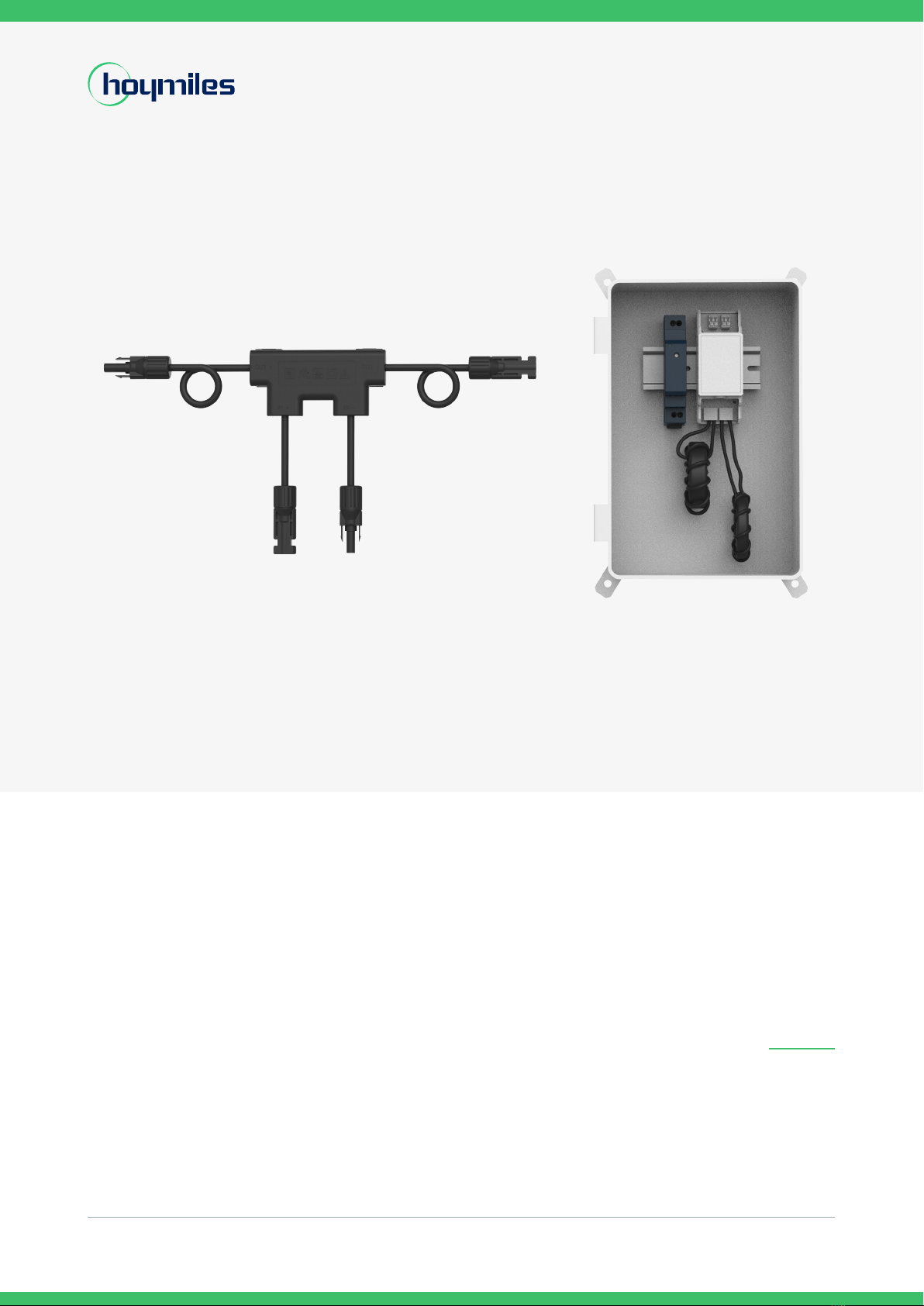
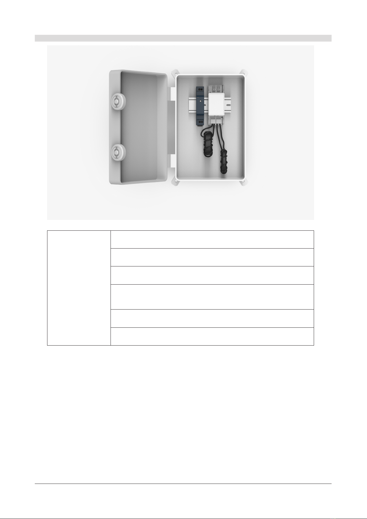
• This manual contains important instructions for installation and maintenance of the Hoymiles
product models HRSD-1C and the Transmitter.
• Risk of electric shock, do not remove the cover, disassemble, or repair, no user-serviceable parts
inside. If it fails, contact Hoymiles Customer Support. Damaging or opening the product will void
the warranty.
• Before installing or using the Hoymiles HRSD-1C System, please read all instructions and warning
markings on the Hoymiles products, relevant sections of your inverter manual, photovoltaic (PV)
module installation manual, and other available safety guides.
• Failure to adhere to these instructions may result in injury or death, damage to the system or
invalidating the factory warranty.
• Perform all electrical installations in accordance with local codes.
• Do NOT disconnect the PV module from the HRSD-1C without first disconnecting the AC power.
• Installation must be performed by trained professionals only. Hoymiles does not assume liability for
loss or damage resulting from improper handling, installation, or misuse of products
• Do not attempt to install in inclement weather.
• Be aware that the body of the running HRSD-1C is the heat sink and can reach high temperatures.
To reduce the risk of burns, do not touch the body of the HRSD-1C.
• Do not operate the HRSD-1C if they have been physically damaged. Check existing cables and
connectors and ensure they are in good condition and appropriate in rating. Do not operate HRSD-
1C with damaged or substandard wiring or connectors.
• Do not connect or disconnect under load. Turning off the Inverter and/or the HRSD-1C products
may not reduce this risk. Internal capacitors within the inverter can remain charged for several
minutes after disconnecting all power sources. Verify capacitors have discharged by measuring a
voltage across inverter terminals before disconnecting wiring if service is required. Wait 30 seconds
after rapid shutdown activation before disconnecting DC cables or turning off DC disconnect.
• The transmitter control power supply MUST be on the same AC branch circuit as the inverter to
meet rapid shutdown requirements.
© 2022 Hoymiles Power Electronics Inc. All rights reserved.

Rapid Shutdown User Manual
© 2022 Hoymiles Power Electronics Inc. All rights reserved. 01
1. Product
1.1 HRSD-1C
Features
• Meets NEC2017&NEC2020 690.12 requirements
• Meets Sunspec RSD requirements
• PLC communication,
realize rapid shutdown with Transmitter
• Plug & play, no confguration required
• Lower power consumption and wider operating voltage range
• Much lower than arc noise. No risk of triggering AFCI
As part of Hoymiles rapid shutdown solution for PV system, HRSD-1C can be connected with one module. It
meets NEC2017, NEC 2020, UL 1741 and Sunspec Rapid Shutdown requirements, guaranteeing PV system
safety.
When installed with and receiving a “permission to operate” signal from Hoymiles Transmitter, HRSD starts
proper operation of PV system. In case of emergency, PV system would enter module-level rapid shutdown
mode by simply disconnecting the AC power of Transmitter or using an external initiator.

Rapid Shutdown User Manual
© 2022 Hoymiles Power Electronics Inc. All rights reserved. 02
1.2 HT10
Features
• Meets NEC2017&NEC2020 690.12 requirements
• Meets SunSpec RSD requirements
• Equipped with single/dual core
• Realize rapid shutdown by simply powering o the transmitter or using an
external initiator
The Transmitter HT10 is part of Hoymiles Rapid Shutdown solution. When paired with Hoymiles rapid shutdown
HRSD and powered on, HT10 sends a “permission to operate” signal to HRSD, to make PV modules connected
in series and then connect to string inverter, thus producing power.
In case of emergency, PV system would enter module-level rapid shutdown mode by simply disconnecting the
AC powerof Transmitter or using an external initiator.

Rapid Shutdown User Manual
© 2022 Hoymiles Power Electronics Inc. All rights reserved. 03
1.3 HT10-Kit
Features
• Meets NEC2017&NEC2020 (690.12) and Sunspec RSD requirements
• Module-level rapid shutdown with Hoymiles HRSD
• Equipped with single/dual core
• Realize rapid shutdown by simply powering o the transmitter or using an
external initiator
• Weatherproof outdoor enclosure
• Includes power supply
Hoymiles Transmitter HT10-Kit is part of a rapid shutdown solution when paired with Hoymiles rapid shutdown
HRSD. While powered on, HT10-Kit sends a “permission to operate” signal to HRSD to keep the PV modules
connected in series to the string inverter and producing power.
PV system equipped with HRSD and HT10-Kit enters module-level rapid shutdown by simply disconnecting the
AC power of the Transmitterduring emergencies.
Hoymiles Transmitter Outdoor Kit includes one Transmitter, one or two cores, 85~264V power supply and
outdoor enclosure.

Rapid Shutdown User Manual
© 2022 Hoymiles Power Electronics Inc. All rights reserved. 04
2. System Overview
The HRSD-1C requires a Transmitter or inverter with built-in transmitter for operation.
The Transmitter is installed in line with a solar PV inverter.
The HRSD-1C starst in the OFF position and measures 1V at the output. When power is supplied to the
Transmitter, the HRSD-1C turns ON and allows full PV module voltage. The HRSD-1C constantly receives a
“permission to operate” signal from the Transmitter.
When power to the Transmitter is cut, this “permission to operate” signal ceases, sending every HRSD-1C into
shutdown mode with output reduced to 1V.
In this way, PV array enters rapid shutdown in event of AC grid loss.
~
~

Rapid Shutdown User Manual
© 2022 Hoymiles Power Electronics Inc. All rights reserved. 05
3. Installation Notes
• Installation MUST comply with local regulations and technical rules.
• Perform all electrical installations in accordance with local codes.
• Be aware that only qualified professionals should install and/or replace the HRSD-1C.
• Before installing or using an HRSD-1C, please read all instructions and warnings in the technical documents
and on the inverter system itself as well as on the PV array.
• Be sure to verify the voltage and current specifications of your PV module match with those of the HRSD-1C.
• Never apply an external voltage source to a module or string equipped with HRSD-1C.
• HRSD-1C is shipped in the OFF position and will measure 1V at the output when the “permission to operate”
signal is not present.
• Failing to follow the sequence of installation steps may result in HRSD-1C damage not covered under warranty.
• Connect HRSD-1C to its respective modules before connecting its outputs in series.
• Install HRSD-1C before powering on the Transmitter.
• If parallel string connections are needed, first connect the HRSD-1C to the PV modules, then connect all
outputs of HRSD-1C in series, and finally pass one side (+ or -) of the string through the transmitter to turn the
system ON.
• Do not touch any live parts in the system, including the PV array, when the system has been connected to the
electrical grid.
• Place rapid shutdown system label no more than 1m (3ft) from initiator (AC disconnect) or service panel
containing means of disconnection if not at same location.

Rapid Shutdown User Manual
© 2022 Hoymiles Power Electronics Inc. All rights reserved. 06
4. Installation
4.1 HRSD-1C Installation
A ). Buckle HRSD-1C on the PV module frame. HRSD-1C can be installed anywhere on the PV module frame.
Mounting Brackets
Method 1 (Recommended)
Allow a minimum of 1.5 cm of space between the roof and the HRSD-1C enclosure to ensure ventilation and heat dissipation
Method 2
Allow a minimum of 1.5 cm of space between the roof and the HRSD-1C enclosure to ensure ventilation and heat dissipation

Rapid Shutdown User Manual
© 2022 Hoymiles Power Electronics Inc. All rights reserved. 07
B ). Connect modules to inputs of HRSD-1C. Each HRSD-1C must have a PV module connected to its inputs.
Output + Output -
Input + Input -
C ). Connect the outputs of HRSD-1C in series.
Note:
When installing HRSD-1C, connect the input cables to the PV module before connecting the HRSD-1C output cables in
series.
If disconnecting HRSD-1C, disconnect the HRSD-1C output cables from the string before disconnecting the input
cables from the PV module.
Connectors from different manufacturers cannot be mated with each other.
Transmitter must be powered off during HRSD-1C installation.
HRSD-1C output Voltage is 0.9V to 1.1V when Transmitter “permission to operate” signal is not present.
Max. string length: 30 modules
Max. cable length from inverter (+) to inverter (-): 1000ft (300m)

Rapid Shutdown User Manual
© 2022 Hoymiles Power Electronics Inc. All rights reserved. 08
4.2 HT10 Installation
A ). - Mount Transmitter HT10 and power supply on DIN rail.
- Connect DC leads from power supply to Transmitter.
- Connect Core to Transmitter HT10.
- If there is only one core that needs to be connected, please connect Core 1 first.
Din Rail PSU
Core 1
Transmitter
Din Rail PSU
Core 1
Transmitter
Core 2
4
L
N
-12 V
+12 V
GND
12V
INITIATOR-
INITIATOR+
LED 1
LED 2
LED 2
CORE 1
CORE 2
L
N
-12 V
+12 V
GND
12V
INITIATOR-
INITIATOR+
LED 1
LED 2
CORE 2
CORE 1
LED 2
4

Rapid Shutdown User Manual
© 2022 Hoymiles Power Electronics Inc. All rights reserved. 09
B ). - Pass either positive homerun or negative homerun through cores.
- Connect wires to AC side of power supply.
*Only positive homerun or negative
homerun through core
*Only positive homerun or negative
homerun through core
*Only positive homerun or negative
homerun through core

Rapid Shutdown User Manual
© 2022 Hoymiles Power Electronics Inc. All rights reserved. 10
C ). - Connect the serially connected outputs of HRSD-1C to the inverter with a DC cable.
- Turn on AC power to Transmitter HT10 power supply to activate the “permission to operate” signal.
GRID
Note:
Install HRSD-1C before powering on Transmitter HT10-Kit.
Transmitter HT10-Kit power supply must be on the same AC branch circuit as the inverter to meet rapid
shutdown requirements.
When the PV system is operating, the Power LED1 should be lit and the Signal LED2 should be blinking.
Place rapid shutdown system label no more than 1m (3ft) from Transmitter or AC disconnect if not at the same
location.
Note:
Max. number of strings per Core*: 5 (75A core) or 15 (150A core)
Max. current per Core: 75A or150A
Max. cable length from inverter (+) to inverter (-): 1000ft (300m)
*With Φ 6 mm DC cable diameter (without DC connector)

Rapid Shutdown User Manual
© 2022 Hoymiles Power Electronics Inc. All rights reserved. 11
4.3 HT10-Kit Installation
A ). - Mount Transmitter HT10-Kit and power supply on DIN rail.
- Connect DC leads from power supply to Transmitter HT10-Kit.
- Connect Core to Transmitter HT10-Kit. If there is only one core that needs to be connected, please connect
Core 1 first.
L
N
-12 V
+12 V
GND
12V
INITIATOR-
INITIATOR+
LED 1
LED 2
CORE 2
CORE 1
LED 2
Din Rail PSU
Core 1
Transmitter
*85-264VAC or 180-550VAC PSU can be
used.
180-550VAC PSU isolation class I requires
grounding.
85-264VAC PSU isolation class II does not
require grounding.
L
N
-12 V
+12 V
GND
12V
INITIATOR-
INITIATOR+
LED 1
LED 2
LED 2
CORE 1
CORE 2
4
Din Rail PSU
Core 1
Transmitter
Core 2
4

Rapid Shutdown User Manual
© 2022 Hoymiles Power Electronics Inc. All rights reserved. 12
B ). - Pass either positive homerun or negative homerun through cores.
- Connect wires to AC side of power supply.
*The waterproof accessories are
not supplied and need to be pre-
pared by the installer.
*Only positive homerun or negative
homerun through core
* AC Wires for PSU
*Only positive homerun or negative
homerun through core
*Only positive homerun or negative
homerun through core

Rapid Shutdown User Manual
© 2022 Hoymiles Power Electronics Inc. All rights reserved. 13
C ). - Connect ground wires.
- Ground all conduit connections.
- The nonmetallic enclosure does not provide bonding between conduit connections.
- Use grounding-type bushings and jumper wires.
D ). - Connect the serially connected outputs of HRSD-1C to the inverter with a DC cable.
- Turn on AC power to Transmitter HT10-Kit power supply to activate the “permission to operate” signal.
GRID
Note:
Install HRSD-1C before powering on Transmitter HT10-Kit.
Transmitter HT10-Kit power supply must be on the same AC branch circuit as the inverter to meet rapid
shutdown requirements.
When the PV system is operating, the Power LED1 should be lit and the Signal LED2 should be blinking.
Place rapid shutdown system label no more than 1m (3ft) from Transmitter or AC disconnect if not at the same
location.
Note:
Max. number of strings per Core*: 5 (75A core) or 15 (150A core)
Max. current per Core: 75A or150A
Max. cable length from inverter (+) to inverter (-): 1000ft (300m)
*With Φ 6 mm DC cable diameter (without DC connector)

Rapid Shutdown User Manual
© 2022 Hoymiles Power Electronics Inc. All rights reserved. 14
4.4 Conduit Drilling Guide
Enclosure Drilling Guide for .75” Conduit
Enclosure Drilling Guide for 1” Conduit

Rapid Shutdown User Manual
© 2022 Hoymiles Power Electronics Inc. All rights reserved. 15
5. Technical Specifiications
5.1 HRSD-1C
Electrical
Input Voltage Range 8-80V
Maximum Current 15A (20A or 25A optional)
Maximum System Voltage 1000V (1500V optional)
Communication Type Sunspec PLC
Shutdown Output Voltage 1V
Power Consumption 200mW
Mechanical
Input Connectors MC4 (standard)
Input Cable Length 0.15m
Output Connectors MC4 (standard)
Output Cable Length 1.2m1
Dimensions 113 x 54 x 16mm
Environmental
Operating Temperature Range -40°C to +85°C (-40°F to +185°F)
Outdoor Rating IP68/NEMA6P
Compliance
Safety UL1741, CSA C22.2 No. 330-17, IEC/EN 62109-1
EMC FCC Part15 Class B, ICES-003, IEC/EN 61000-6-1/-2/-3/-4
*1: Fits PV module in landscape and portrait installation.
Unit : mm
25
113
54
1200
150
1200 16

Rapid Shutdown User Manual
© 2022 Hoymiles Power Electronics Inc. All rights reserved. 16
5.2 HT10
Electrical
Transmitter Input Voltage 12VDC (+/-2%)
Transmitter Input Current 1A
Communication Type Sunspec PLC
Core
Max. Number of Cores Connected 2
Max. Current per Core 75A 150A
Max. String Voltage 1500VDC
Max. Number of Strings per Core15 15
Mechanical
Dimensions 93 x 36.5 x 53 mm
Mounting Type DIN35 Rail
Environmental
Operating Temperature Range -40°C to +85°C (-40°F to +185°F)
Outdoor Rating IP30/NEMA1
Compliance
Safety UL1741, CSA C22.2 No. 330-17
EMC FCC Part15 Class B, ICES-003
*1: Φ 6 mm DC cable diameter
93
36.5
64
28
200
200
47
17
Transmitter
Unit : mm
Core-150A Core-75A

Rapid Shutdown User Manual
© 2022 Hoymiles Power Electronics Inc. All rights reserved. 17
5.3 HT10-Kit
Electrical
Power Supply Input Voltage 85-264VAC
Transmitter Input Voltage 12VDC (+/-2%)
Transmitter Input Current 1A
Communication Type SunSpec PLC
Core
Max. Number of Congure Core 2
Max. Current per Core 75A 150A
Max. String Voltage 1500VDC
Max. Number of Strings per Core15 15
Mechanical
Dimensions 198.5 x 298 x 179 mm
Mounting Type Wall mounted
Environmental
Operating Temperature Range -40°C to +85°C (-40°F to +185°F)
Outdoor Rating IP65/NEMA4
Compliance
Safety UL1741, CSA C22.2 No. 330-17
EMC FCC Part15 Class B, ICES-003
*1 According to the cable diameter Φ 6 mm, if cable diameter is more than Φ 6 mm, Strings Per Core will be reduced.
Care should also be taken not to exceed the allowable current.
90
298
18
198.5
93
36.5
179
64
28
200
200
47
17
TransmitterUnit : mm Core-75ACore-150A
Power Supply
(optional)
Other manuals for HRSD-1C
1
This manual suits for next models
2
Table of contents
Popular Industrial Equipment manuals by other brands

Walinga
Walinga Airlock 1008 Operator's manual

Somex
Somex MAX40COD Technical document

Hamworthy
Hamworthy 563216020 Installation, commissioning and servicing instructions

KSB
KSB AmaDrainer Box Box Z2 B Installation & operating manual

Parker
Parker Finite JDK5000V Installation, operating and maintenance manual

Wizard
Wizard FS Operating and service manual

Trumpf
Trumpf F 300-2 Plus Operator's manual

Labelmate
Labelmate TWIN-CAT-2 user manual

schmersal
schmersal AZM201Z-ST-T-1P2PW-A-2965-1-DU manual

PPI
PPI STATIC SHAFT PULLEY Operation & maintenance manual

Raytools
Raytools BW101-GS Series user manual

PAW
PAW HeatBloC K33 - DN 20 Installation and operation instruction