Region: Europe AP040873 REV1.1 ©2023 Hoymiles Power Electronics Inc. 03
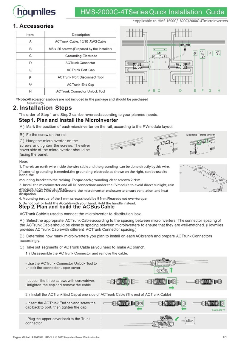
a. Before stripping the cable, check and ensure that the HMS Cable
Connector can be separated into six parts.
b. Push the parts through the AC cable in the correct order.
c. Strip off 40±5 mm of the outer jacket with a diagonal cutter. Then,
use a wire stripper to strip the insulation, exposing 6-7.5 mm
of the conductor.
d. Insert the conductor into the terminal pin, crimp the connection,
and push the crimped cable through the wire holder.
e. Plug the fixed cable into the HMS Cable Connector. Then firmly
tighten the nut using the HMS Disconnect Tool.
Connect the AC End Cable to the last HMS Trunk Cable Connector in a
series of cables. Listen for a click as they engage.
d. Make the AC End Cable
e. Connect the AC End Cable
Use the cable ties to attach all cables to the racking.
cover wire holder gasket
gasket
nut
nut
compression ring
compression ring
terminal pins
321
strip the cable
from this end
40±5 mm
6-7.5 mm
Black
Blue
or
Red
Brown
or
Green&Yellow
Click
Torque: 2.5±0.5 N·m
Click
g. Connect to the Distribution Box
f. Manage the AC Trunk
a. Turn ON the AC disconnect or circuit breaker for each AC output line.
b. Turn ON the main utility-grid AC circuit breaker. Wait five minutes
for the system to start producing power.
Check the LED on the connector side of the microinverter.
For the single-microinverter system, connect the other end of Plug
and Play Cable to the socket.
For the multi-microinverter system,
40±5 mm
N
LPE
Click
* Use the cable tie to fasten
around the central portion
of an HMS Cable Connector.
a. Mount the PV modules above the microinverters.
b. Connect the DC leads of PV modules to the corresponding DC inputs
on the microinverters.
Warning:
Before installing the PV modules, ensure that all microinverters and inter-wiring
connections are properly set up.
*To enhance the clarity of
the structure, the product
proportions and installation
locations have been adjusted
accordingly.
*The product proportions have
been adjusted to enhance the
illustration of the structure.
2Connect the PV Modules
Connect the other end of the AC End Cable to the distribution box.
Warning:
Adhere to local wiring codes
for wiring safety.
Wire Colors
L
N
PE
Brown
Blue
Green&Yellow
LED
Five green flashes (0.3s gap)
Fast green flashing (1s gap)
Red flashing (1s gap)
Startup success
Producing power
Not producing power, AC grid fault (voltage
or frequency is not within specification )
indicates
Notice:
Specifications for the
desired AC cable:
Wire Type
Core
Maximum Voltage
Cross-Section
Outdoor Use, Copper Wire
Three
600 V
≤16.5 mm
1Complete the Installation Map
a. Peel off the removable serial number label (located near the antenna)
from each microinverter.
b. Affix the label to the respective location on the installation map.
c. Record the Wi-Fi AP Initial Password of each microinverter for later
configuration.
4143xxxxxxxx
4143xxxxxxxx
4
DC Side Electrical Installation
5
Start-up
b. Check the LED Statusa. Energize the System
LED
