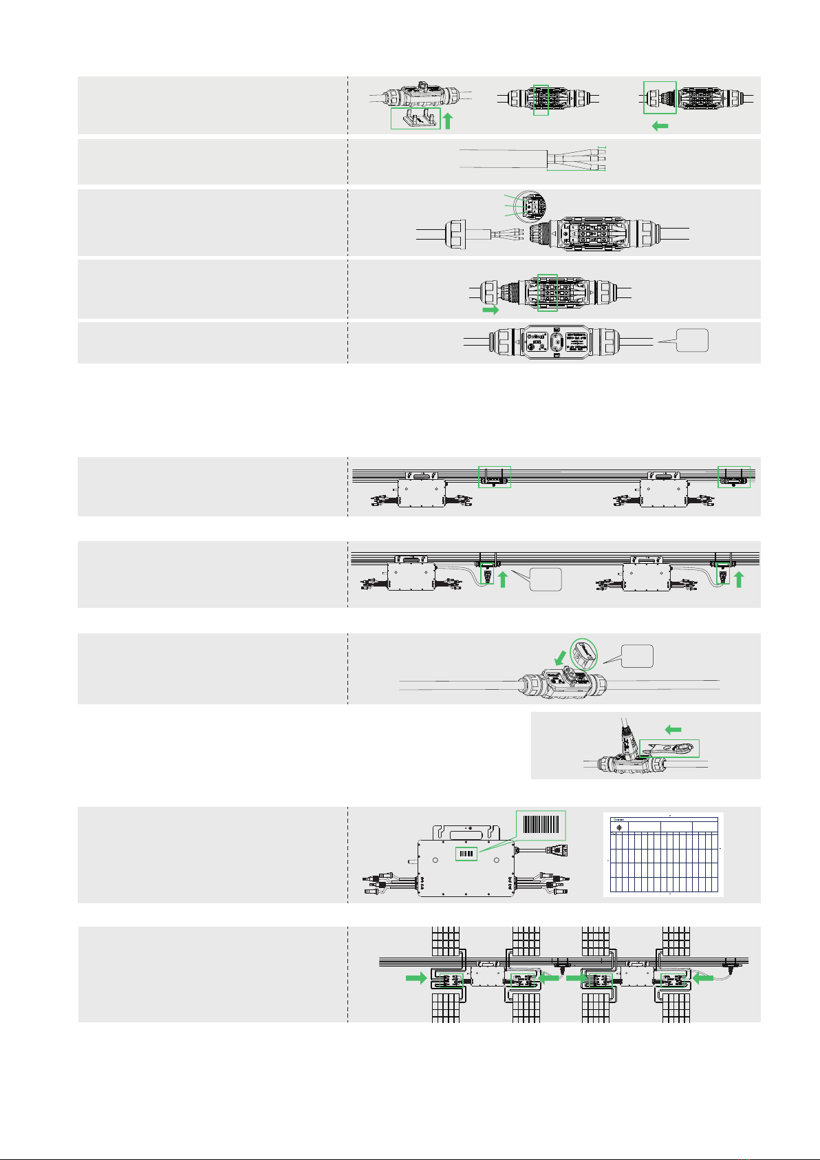
Step 5. Connect PV Modules
Step 6. Energize the System
A ) Mount the PVmodules above the
microinverter.
B ) Connect the PV modules’ DC cables to the
DC input side of the microinverter.
Note:
1. Tightening torque of the cap: 4.0±0.5 N·m.Pleasedo not over-torque.
2. Torque of locking screw:0.4±0.1 N·m.
3. Do not damage the sealing ring in the ACTrunk Connector during disassemblyand
assembly.
Step 4. Create an Installation Map
A ) Peel the removable serial number label from
each microinverter.
B ) Ax the serial number label to the respective
location on the installation map (pleaserefer
to the User Manual).
3 ) Install ACend cable on the other side of AC Trunk Cable (connected to the distribution box)
Note:
1. Makesure that the ACTrunk Connectors are kept away from any water-channeling
surface.
2. In case you need to remove the inverter ACcable from ACTrunk Connector, please
usethe
ACTrunk Port Disconnect Tool and insert the tool into the side of ACSubConnector to
complete the removal.
Product information is subject to change without notice. (Pleasedownload referencemanuals at
www.hoymiles.com).
138264700571
138264700571
D ) Repeat the above steps, lay out the cable on the rail as appropriate so that the microinverters can be connected to
the Trunk connectors.
Step 3. Complete the AC Connection
- Unlock the port upper cover,loosen the screws
with screwdriver and remove the extra cable.
(Skipthis step if there is no cable at this side.)
- Prepare a segment of ACcable with suitable
length to connect to the distribution box, with
stripping requirements fulfilled.
- Insert the cable into the cap in a way that the
L, N and PElines are in corresponding slots.
- Tighten the screwsand tighten the cap back
to the port.
- Plug the upper cover back to the Trunk
connector.
Region: Global AP040511 REV1.1 © 2022 Hoymiles Power Electronics Inc. 02
B ) Connect the ACend cable to the distribution box, and wire it to the local grid network.
A) Turn on the ACbreaker for the branch circuit.
B) Turn on the main ACbreaker for the house. Your system
will start to generate power in about two minutes.
Step 7. Set up Monitoring System
Pleaserefer to the DTU User Manual or DTU Quick Installation
Guide, and Quick Installation Guide for S-MilesCloud to install
the DTUand set up monitoring system.
E ) Attach the ACTrunk Cable to the mounting
rail and x the cable with tie wraps.
A ) Push the ACSub Connector from microin-
verter to the ACTrunk Connector until it clicks.
C ) Please plug the ACTrunk Port Cap in any
vacant ACTrunk Port to make it water and
dust-proof.
L
PE
4.0±0.5N·m
0.4±0.1N·m
N
click
click
click
8±1mm
40±5mm
Tosheet______
Tosheet______
Tosheet______
Tosheet______
Sheet_____of_____
Hoy miles Micr oinve rterI nstal lati onMap
PleaseMakeNforNorth
1
A
B
C
D
2 3 4 5 6 7 8 9 10 11 12 13 14 15 16
COLUMN
ROW
AP040228 V1.3
CustomerInformati on: DTUSerialNumber
Azimuth:
Tilt:
Paneltype:


