HOZAN HS-603 User manual

※ダイヤフラム式ポンプはゴム製弁膜を振動させることでエアー
の吸入排気をする方式です。
1
仕 様
各部の名称と入組明細
HS-603
ホットエアSMD除去機
このたびはホーザン HS-603 ホットエアSMD除去機 をお買い上げいただき、まことにあり
がとうございます。この取扱説明書をよくお読みになり、正しくお使いください。また、お読み
になったあとも大切に保管してください。
取扱説明書
21L/分(60Hz)
AC100V 50/60Hz
消費電力
設定温度
ヒーター
ポンプ
330W
セラミックヒーター
ダイヤフラム式
最大吐出量
※
ご注意 :旧HS‐601/602とHS-603の電源コネクター
は形状が異なり、ブロアの互換性はありません。
(ノズルは兼用可能です。)
電源スイッチ
ステーション
温度調整ツマミ
風量調整ツマミ
ノズル
(別売品)
ホルダー
エアホース
電源コネクター
ブロア
ヒータースイッチ
温調モニタランプ
HS-32
2ピン変換
アダプター
(別売)
※2ピンプラグへ変換
してご使用になる場
合はアースを確実
にとってください。
ノズルセッター
ピンセット
付属品
ホルダー取り付け用ビス2本
コテ部 230g
外形寸法
(ステーション部) (突起物含まず)
5kg
ブロア全長
■3ピンプラグ仕様

ご使用上の注意
2
注意文の警告マークについて
この取扱説明書ではご使用上の注意事項を次のように区別しています。
警告 …重傷をともなう重大事故の発生を想定してのご注意
注意 …傷害や物的損害を想定してのご注意
なお、注意 として記載されていても、あるいは特に記述がなくても、状況によっては重大
な結果をまねく恐れがあります。正しく安全にご使用ください。
1.電源電圧は、交流100Vをご使用ください(50Hz、60Hz共用)。規定以上の電圧を
加えると、故障や火災の原因になります。
2.電源を入れたまま長時間放置すると、ヒーター寿命を短くするばかりか思わぬ事故に
つながる恐れがあります。使用後は必ず電源を切ってください。
3.ノズルからは最高420℃の熱風が吐出します。熱風吐出方向30cm以内には手・顔
など人体の各部およびアルコール・塗料など揮発性の高い化学薬品、また、紙・木・プ
ラスチックなど可燃物を絶対に近づけないでください。また直接熱風がかからないよう
にしてください。
4.ブロアに接続しているエアホース・電源コードには、発熱部を接触させないでください。
5.ノズル交換は、必ず電源スイッチを切り、冷却したのち付属のノズルセッターを用いて
行ってください。(6ページ参照)
6.感電・ヤケド防止のため、ヒーター交換は必ず電源スイッチを切り電源プラグをコンセン
トから抜き、冷却したのちに行ってください。
警告
1.コテホルダーおよびステーションは、振動のない水平で安定した場所に設置してくださ
い。ステーションは横にしたり、逆さにしたり、また衝撃を与えたり、落下させたりしないで
ください。
2.ヒーターはセラミックでできています。水などで急速に冷却しないでください。また、落と
したり、強い衝撃を与えたりしないでください。破損(断線)する恐れがあります。
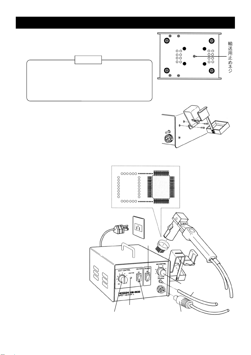
3.必ずステーション底部に取り付けてある輸送用止めネジ(赤色)を外してから運転を開
始してください。輸送用止めネジを外さないで電源を投入しますと、故障を引き起こし
ます。(3ページ参照)
4.修理などで移送する場合は、必ず輸送用止めネジをしっかりと取り付けてください。(3
ページ参照)
注意

電源スイッチ
温度調整ツマミ
風量調整ツマミ
電源コネクター
ヒータースイッチ
温調モニタランプ
ノズル(適合の確認)
ブロア
エアホース
準 備
3
輸送用止めネジの取り外し
●
ステーション側面のビス穴についているビスをいった
ん外し、ホルダーを固定してください。
元のビス1本と、同梱の2本のうち1本を使用し、残り
1本は予備です。
1
開梱が終わりましたらステーション底部に取り付けて
ある輸送用止めネジ(赤色)を外してください。
ホルダーの取り付け
●
輸送用止めネジ
輸送用止めネジを外さないで電源を投入します
と、故障を引き起こしますので必ず取り外してくだ
さい。
このネジは紛失しないように保管し、輸送される
ときは必ず取り付けてください。
注意
装着するノズルが、取り外す
部品に適合しているか確認
のうえ、ブロアにノズルを取り
付けます。
(5ページ「ノズルの選び方」と
6ページ「ノズルの着脱方法」
を参照)
各部の接続
●
2 ブロアをホルダーにセットし
ます。
3 ブロアの電源コネクター
とエアホースをステー
ションに接続します。
4 電源プラグをコンセント
に差し込みます。
5 電源スイッチ・ヒーター
スイッチをONにします。
風量・温度を任意に設定し、
設定温度になるまでしばらく
お待ちください。設定温度に
なりますと、温調モニタランプ
が点滅に変わります。

4
ご使用方法
希望する温度、風量に設定します。
ハンダの種類により、溶融する温度が異なり
ますのでハンダの種類をご確認ください。
使用するノズルにより、吐出する熱風の温度
が異なります。9ページの温度特性表を参考
に温度を設定してください。
1
吐出風量特性
2 ノズルの先端が部品のリードの真上になるよう
ブロアを保持します。
このとき、ノズルと部品を接触させないように
注意してください。
4 取り外し後、パターン部分に残ったハンダをハ
ンダ吸取線(当社H‐37‐1.3など)で除去しま
す。
3 ピンセットの先端を部品の隅に当て、ほんのわ
ずかの力で押しながら加熱します。ハンダが
ゆるむと部品がぐらつきますので素早く取り外
します。
このとき、ハンダの溶解が不十分ですと、パ
ターンが剥離することがありますので、無理に
引きはがしたりせず、再び加熱してください。
吐出エアの勢いはノズルのピン数によって大
きく変わってきます。とくにピン数の少ないノズ
ルをお使いの場合には風量を絞ってお使いく
ださい。
右グラフは吐出口口径φ4の場合の、風量調
整ツマミ位置と吐出風量の関係です。
吐出風量特性
風量調整ツマミ位置
吐出風量( L /分)
〈測定方法〉
吐出口口径φ4の条件で、下記流量計に接続して計測。
風量計 :Model N.T.KSCI‐S型

5
ノズルの選び方
一般的なチップ部品に適合するよう、多数のスタンダードノズルをご用意しています。詳しく
は最新のカタログまたはホーザンのホームページをご覧ください。
適合性については下記をご参照ください。
ノズルピンの種類
SOP QFP PLCC BGA(CSP)
●●=ノズルピンなしに
ベースに直接
あけた穴です。
ノズルピンの内寸法
(H)がリードの肩に合う
ぐらいが適当。
αが短い場合はスモー
ルピンが適当。
ノズルとリードが接しな
いように片側0.5mm
程度内寸法が大きめ
のものが適当。
ノズルの寸法がICの寸
法とほぼ一致していれ
ば適当。
別注ノズルのご用命について
別注ノズルの作成は1個から承ります。
ご用命の際、部品の現品あるいは正式図面をご用意いただければ最良ですが、上図の各
寸法だけでもお見積りできます。ただし、リード列(例:SOPのA)内でリードピッチが一定で
なく大きく開いているものやX軸またはY軸に対して非対称など、特殊形状のものは必ず現
品もしくは正式図面をご用意ください。
ベント(斜め約45°に吐出) ストレート
内径 1.18mmφ
外径 1.48mmφ
スモール
内径 0.68mmφ
外径 0.88mmφ
BGA(CSP)
内径 1.45mmφ
外径 1.81mmφ
内径 1.18mmφ
外径 1.48mmφ

6
ノズルの着脱方法
1.使用直後のノズル、ヒーターホルダー部分は熱くなっています。十分に冷ましてから着
脱をしてください。
2.ヒーターはセラミックでできています。水などで急速に冷却しないでください。また、落と
したり、強い衝撃を与えたりしないでください。破損(断線)する恐れがあります。
注意
ノズルの取り付け
●
ノズルの取り外し
●
付属のノズルセッターの筒状の部分を固定金具の
ロックレバーにかぶせ、引き起こします。
2 ブロアの固定金具をフックに引っ掛けます。
3 ロックします。
ロックが強く、指先での作業が困難な場合は、取り
外し時と同様にノズルセッターを使用してください。
1 ブロアの先端にノズルを乗せます。
ノズルのフックがブロアの固定金具の延長線上に
来るように置きます。
フック
固定金具

⑤のビスを外し、ヒーターホル
ダーをハンドルAから抜きます。
※エアホースはそのまま接続し
ておいてください。
新しいヒーターを逆の手順で取り付けます。
ヒーターをヒーターホルダーから
取り外します。
※ヒーターには抵抗値が明記してあります。この抵抗値は後のヒーターマッチング時
に必要ですので必ずメモしておいてください。
5
1
ヒーター先端内側の穴が、ヒー
ターベースマウンド部に正しくはま
り、乗り上げていないこと。正しくは
まっていないと、エアの通路が確
保できないばかりか、ヒーターカ
バーを取り付けたときや使用中に
ヒーターが破損する恐れがありま
す。
ヒーターツバ部全周で、セラミック
ペーパーを均等にしっかり押さえ、
エアー漏れのないこと。
2
2
1
ヒーターベー
スマウンド部
セラミック
ペーパー
ヒーターツバ部
ヒーター挿入時のチェックポイント
ヒーターの交換
7
熱風が出なくなる原因の大半はヒーター切れです。
ブロアの電源コネクターピン右図の①と③間の抵抗値を測定し、∞であれば
ヒーター切れが疑われます。ブロアを分解し、念のためヒーターリード間の抵
抗を測定し、ヒーター切れが確実となればヒーターを交換します。
ノズル、ヒーターホルダーが十分に冷めた状態でおこなってください。 ①
③ ④
②
新しいヒーターをヒー
ターホルダーに差し込
むときは、破損しない
ようゆっくり差し込んで
ください。そしてエア漏
れのないように右図の
注意事項を参照してく
ださい。
※
※新しいヒーターのリード線は長めです。たるませないで④の端にハンダ付けしたあと、
余分なリード線はカットしてください。
※ネジが配線やホースを傷つけないよう慎重に組み立ててください。感電する恐れが
あります。
※ヒーターのリード線の引き回しは図2を参照してください。
①のビスを外し、ハンドルBを
外します。
1
②のビスを外し、ヒーターカ
バーを外します。
2
③のビスを外し、アース線
(赤または緑)を外します。
3
④の端子にハンダ付けしてある
ヒーターのリード線を外します。
4
図1 ②
HS-605
ヒーター
ヒーターカバー
図2
ハンドルB
ハンドルA
①
⑤
抵抗値を表示
③
アース線
④
6
7

8
ヒーター交換時の再調整方法
再調整をおこなわないままご使用になる
と、異常に温度が上昇する場合があり、大
変危険です。再調整は必ず実施してくださ
い。
警告
ヒーターはそれぞれ固有の抵抗値を有します。
HS-603は温度制御回路の調整をして出荷しております。ヒーターを新しく交換した場
合、温度制御回路の再調整が必要となりますので、次の手順で行ってください。
ステーションのカバーを外します。調整用トリ
マーはフロントパネル裏側の温度制御基板上
にあります。
ヒーター交換作業の際メモした新しいヒーター
の抵抗値を下表に照らし合わせ、トリマーの調
整抵抗値を確認してください。
トリマー
基板
対照表
テスターと調整ドライバーをご用意ください。
●
1
2
確認した調整抵抗値になるようテスターで測
定ポイントAーB間の抵抗値をチェックしなが
ら、トリマーを回してください。
●測定ポイント
A、Bの位置
トリマー
基板 A
B
3
トリマーの
調整抵抗値(Ω)
ヒーターの抵抗値
(Ω) 8.1 8.2 8.3 8.4 8.5 8.6 8.7 8.8 8.9 9.0
815 805 785 770 740 720 715 710 705 680
ヒーターの抵抗値
(Ω)
665 660 650 640 630 620 610 600 595
9.1 9.2 9.3 9.4 9.5 9.6 9.7 9.8 9.9
トリマーの
調整抵抗値(Ω)

9
温度特性(装着するノズルの種類や風量設定の違いにより熱風の温度が異なります。)
測定方法
ノズル先端から1.5mmの距離に熱電対(JIS.K)を固定し、記録計に接続し計測。
記録計
: YEW Model μR-100
※風量調整ツマミ位置 実線 : MAX.時 破線 : MIN.時 一点鎖線 : 7時
HS-611(24ピン)
熱風温度( ℃
)
温度調節ツマミ位置
HS-615(28ピン)
熱風温度( ℃
)
温度調節ツマミ位置
HS-617(2ピン)
熱風温度( ℃
)
温度調節ツマミ位置
HS-618(1ピン)
熱風温度( ℃
)
温度調節ツマミ位置
HS-619(44ピン)
熱風温度( ℃
)
温度調節ツマミ位置
HS-623(12ピン)
熱風温度( ℃
)
温度調節ツマミ位置
HS-624(16ピン)
熱風温度( ℃
)
温度調節ツマミ位置
HS-626(28ピン)
熱風温度( ℃
)
温度調節ツマミ位置
HS-631(36ピン PLCC用)
熱風温度( ℃
)
温度調節ツマミ位置

10 11.04
本社 〒556-0021 大阪市浪速区幸町1-2-12
TEL(06)6567-3111 FAX(06)6562-0024
TEL(06)6567-3132
月曜日から金曜日(祝日を除く)の 9:15~12:00、13:00~17:00
技術的なお問い合わせ

Main switch
Station
Temperature
control
Control monitor
Air volume control
Nozzle
(sold separately)
Blower holder
Air hose
Power supply
connector
Blower
Heater switch
Note:
The power supply connector of HS-603 is different from
HS-600/602(old model), and there is no interchangeability
between the two connectors. But optional nozzles are
interchangeable between them.
HS-32
3-2 pin
Adapter
(Sold separately)
*Be sure to ground
when use convert-
ing by this 3-2 pin
adapter.
Identification of parts and contents
Nozzle setter
Tweezers
Accessories
Holder mounting screws (X2)
1
HS-603
INSTRUCTION MANUAL
Thank you for purchasing the HOZAN HS-603 HOT AIR STATION. With proper care and
handling this fine instrument will provide years of trouble-free operation. Please read this
entire instruction manual carefully before attempting to place this instrument in service.
Please keep this instruction manual available for reference.
Specifications
Setting temperature
21L/min.(60Hz)
Rated voltage / Frequency
Power consumption
Max airflow rate
100 VAC, 50/60 Hz
330 W
Ceramic heater
Pump Diaphragm type *
Heater
* A diaphragm pump features a format in which air intake / exhaust
occurs by the vibration of a rubber membrane valve.
Station
Weight 5kg
178(W)x112(H)x189(D)mm
(not including projecting
parts)
(station)
Blower
overall length 190mm
(not including air hose)
230g
■3-pin plug type

These symbols are used throughout the instruction manual to alert the user to potential
safety hazards as follows :
Warning …Notice when incorrect handling could cause the user's death or serious
injury.
Caution …Notice when incorrect handling could cause injury to the user or material
damage.
Even if the instructions do not have Caution mark, there are some possibilities for a
serious situation. Follow the instructions.
Warning and caution symbols
Precautions
2
1. Do not use the power input other than specified. This could cause a malfunction or a
fire.
2. Do not leave the power switch on when the unit is not in use for securing longer life of
heater and to escape unexpected accidents.
3. The maximum the temperature of the heated air blown out from the nozzle is 420°C.
Keep your hands, face or other body parts, highly volatile chemicals such as
alcohol and paint, and combustible materials such as paper, wood and
plastic, at least 30 cm away from the heater in the direction of the blown air.
Moreover, do not blow heater air directly onto anything.
4. Do not bring the hot part into contact with the air hose and the power cord.
5. When replacing the nozzle, turn off all switches and use the nozzle setter to replace
the nozzle.
6. When replacing the heater, turn all switches off and disconnect the power cord from
the outlet in order to prevent an electric shock and a burn.
Warning
1. Place the station and holder on a level and stable surface without vibration.
Do not lay down the station, nor place upside down, nor drop, give a shock to the
station.
2. As the heater is made of ceramic, do not cool it down quickly with water etc. and do
not drop or give a strong impact. This could cause a damage of heater.
3. Surely remove the shipping screw (red color) on the bottom of the station before turn
on the power. Otherwise, this could cause a trouble of the station.
(refer to the page3).
4. Securely tighten the shipping screw (red screw on the underside of station) before
transporting the unit. (refer to the page 3)
Caution

● Removing the shipping screw
After unpacking the HS-603, remove the shipping
screw (red color) on the bottom of the station.
If turn on the power without removing the screw,
this could cause a trouble of the station.
When transporting the HS-603, the shipping
screw should be screwed. Store the screw
carefully for this purpose.
Caution
Nozzle (checking applicability)
Air hose
Blower
Heater switch
Temperature control
Control monitor
Power supply
connector
Air volume control
Main switch
Power plug
● Connection of each part
1 Check that the nozzle being
used is appropriate for the
component to be desoldered.
Attach the desired nozzle to
the blower.
Refer to “Nozzle selection” on
page 5 and “Replacing the
nozzle” on page 6.
2 Place the blower into the
blower holder.
3 Connect the blower’s
power supply connector
and the air hose to the
station.
4 Plug the power cord to
the wall outlet.
5 Turn on the power
switch and the heater switch.
Set the air volume and
temperature as desired,
then wait until the temperature of
the blown air becomes hot enough,
as the heater as the heater warms
up, the monitor lamp will begin flick-
ering regularly.
Before operation
3
●
Once remove the screw in the screw hole on the side
of the station, then fix the blower holder using the
original screw and one of the provided two screws.
Attaching the blower holder
Shipping screw

4
4
Operation
Set the temperature control and the air vol-
ume control at the desired settings.
The appropriate temperature for melting sol-
der depends to solder types, e.g. it is relative-
ly higher for read-free solder. Also depends to
the nozzle to be used. Therefore, decide the
setting temperature referring to “Temperature
characteristics” on page 9.
1
2 Hold the blower so that the tip of the nozzle is
directly above the lead wires of the compo-
nent. Take care not to let the nozzle touch the
component at this time.
After the component has been removed, there
will still be some solder remaining on the pat-
tern. Use HOZAN-WICK (desolder braid) such
as H-37-1.3 to clean it.
3 Place the tips of the tweezers against the
corner of the component and push very slight-
ly while heating. When the solder is sufficient-
ly melted, the component will move, and so it
should then be quickly removed.
The pattern peels off if the solder in not suffi-
ciently melted. In such case, reheat the solder
rather than pulling the component off by force.
Air volume characteristics
The blown air volume will vary greatly with the
number of pipes of the nozzle. Turn down the
air volume control if use a nozzle with very
few pipes.
The right graph shows the relationship be-
tween the position of air volume control and
the blown air volume when the overall cross
section of the pipes are 4 πmm2.
Air volume characteristics
Position of air volume control
Air volume (L/min.)
<Measurement method>
Connected to the following flow rate meter and
measured with a 4 mm diameter nozzle.
Flow rate meter : Model N.T.K SCI-S

5
When ordering custom nozzles
Custom nozzle(s) can be made even one piece.
When ordering the sample of component or an accurate drawing is required. We are able
to quote on receipt of sample or dimensions given in above chart. However, if the pitch of
the leads are not even or with very large, or if they have non-symmetrical shape along the
X/Y axis, then an actual component or accurate drawing should be required.
Types of nozzle pipe
inner dia. 1.18mm φ
outer dia. 1.48mm φ
inner dia. 0.68mm φ
outer dia. 0.88mm φ
inner dia. 1.45mm φ
outer dia. 1.81mm φ
inner dia. 1.18mm φ
outer dia. 1.48mm φ
Straight Thin BGA (CSP)
Nozzle selection
Various standard nozzles are available for popular chip components.
See the latest HOZAN catalog or web site for further reference.
Refer to the following chart for applicability.
For SOP For QFP For PLCC BGA (CSP)
●●: Drilled holes
on the nozzle
base plate
The distance marked
“H” is recommended to
be a little shorter than
actual measure.
The distance is meas-
ured at inside of pipe to
pipe.
The pattern of the lead
marked “α” is little, thin
type of pipe is suitable.
The distance is set to
1.0 mm larger than the
measure, not to touch
the leads.
The size is recommend-
ed to put in the compo-
nent without room.
Lead
pitch

Removing the nozzle
●
Raise the fasteners inserting the cylindrical part of
the nozzle setter into the lock knob of the fastener.
6
Replacing the nozzle
1. The nozzle and the part of the heater holder is very hot. Replace nozzles after cool
them down enough.
2. As the heater is made of ceramic, do not cool it down quickly with water etc. and do
not drop or give a strong impact. This could cause a damage of heater.
Caution
Attaching the nozzle
●
2 Latch the fasteners to the hooks of the nozzle.
3 Lock the fasteners.
If it is hard to lock, use the nozzle setter similarly
as removing a nozzle.
1 Place the nozzle on the top of the blower.
Position the hooks aligning the fasteners of the
bower. Hook
Fastener

Remove the screw⑤and pull out
the base from the handle A.
*Keep the air hose as it is.
5
Exchanging order of the heater
7
The cause of that the unit does not blow hot air is mostly a heater break.
It is suspicious of a heater break if the resistance value is infinity between the
connector pin Nos. 1 and 3 of the power supply connector.
Reassemble the blower and measure the resistance between the heater lead
wires just to make sure that it is a heater break.
Exchange the heater after the nozzle and the base have gotten cool enough. ①
③ ④
②
Remove the screw①and
take out the handle B.
1
Remove the screw②and
take off the heater cover.
2
Remove the screw③and
take off the ground wire (red or
green).
3
Remove the lead wire of the
heater soldered to the terminal
④.
4
Handle A
HS-605
Heater
Heater cover
Fig. 2
Handle B
①
③
⑤
④
Ground
wire
② Fig. 1
Pull the heater out of the base.
6
* Insert the new heater
slowly to the base not to
damage it.
Refer to the cautions as
shown in the right
illustration to prevent the
air leakage.
Install the new heater following the reverse order.
* The resistance is specified on the heater.
Be sure to make a note of the resistance as it is related with the process of matching
the heater resistance.
* Assemble it carefully not to damage the wires and the hose with screws. Otherwise,
it could cause an electric shock.
*Refer to Fig. 2 for wiring the lead of the heater.
* The lead wire of the new heater is relatively long. Solder them to the ends of
terminals④ without sagging and cut off the rests.
7
2
1
Mound
of the base
Ceramic
paper
Heater brim
part
1
2
Check points when installing the
heater
Fit the heater hole at the bottom to
the mound of the base. Otherwise,
not only it narrow down the air
through hole but could cause a
damage of heater when put the
heater cover on or during use.
Push the ceramic paper evenly
around the heater brim part and do
not leak the air.

8
Adjustment of the temperature control circuit
If use without trimmer adjustment, under
certain circumstance, the temperature will
go up abnormally and cause a dangerous
result. Should carry out the adjustment.
Warning
Each optional heater has individual resistance. The trimmer on the temperature control
circuit of HS-603 is already adjusted when shipping. It is necessary to readjust the trimmer
when the new heater is installed. Proceed with the following order.
トリマー
基板
Prepare a multimeter and an alignment screwdriver.
●
Remove the cover of the station. The trimmer
is on the temperature control PCB on the back
of the front panel.
1
Find the trimmer resistance in the cross-
reference table referring to the new heater
resistance which was taken notes.
2
●Measurement
point A and B
PCB A
B
Trimmer
Turn the trimmer, checking the resistance be-
tween the check point A and B with multime-
ter, to obtain the trimmer resistance.
3
Cross-reference table
Trimmer resistance
to be adjusted
(Ω)
Heater resistance
(Ω) 8.1 8.2 8.3 8.4 8.5 8.6 8.7 8.8 8.9 9.0
815 805 785 770 740 720 715 710 705 680
Heater resistance
(Ω)
665 660 650 640 630 620 610 600 595
9.1 9.2 9.3 9.4 9.5 9.6 9.7 9.8 9.9
Trimmer resistance
to be adjusted
(Ω)

9
Temperature characteristics
Measurement method
Secure a thermocouple (JIS.K) in position 1.5 mm away from the tip of the nozzle, connect
it to a recorder and take the measurement. Recorder : YEW Model μR-100
————- Airflow at MAX. — - — - — - — Airflow at 7 — — — — Airflow at MIN.
(The temperature of the blown air will vary with the type of nozzle attached and the air volume setting.)
Temperature (℃)
Heat control knob
HS-611 1.18mmφ×24 HS-615 1.18mmφ×28
Temperature (℃)
Heat control knob
HS-617 1.33mmφ×2
Temperature (℃)
Heat control knob
Temperature (℃)
Heat control knob
HS-618 2.0mmφ×1
Temperature (℃)
Heat control knob
HS-619 1.18mmφ×44
Temperature (℃)
Heat control knob
HS-623 1.18mmφ×12
Temperature (℃)
Heat control knob
HS-624 1.18mmφ×16
Temperature (℃)
Heat control knob
HS-626 1.18mmφ×28
Temperature (℃)
Heat control knob
HS-631 1.18mmφ×36

HEAD OFFICE : 1-2-12 Saiwaicho, Naniwa-ku, Osaka 556-0021, Japan
Tel : 81-6-6567-3111
Fax : 81-6-6562-0024
11.04
Table of contents
Other HOZAN Power Tools manuals