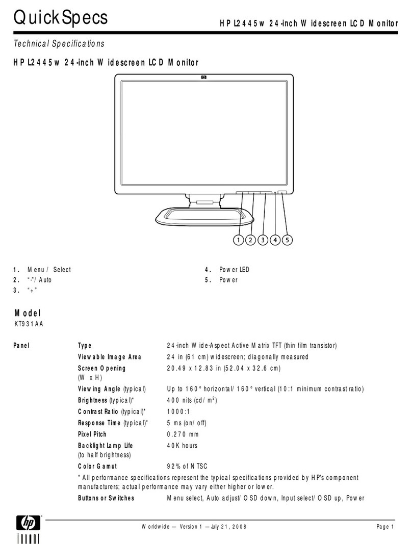
HP LP2475w - 24" LCD Monitor User manual

24" LCD Color Monitor HP LP2475w
1
Service
Service
Service
Horizontal Frequency
30-94kHz
TABLE OF CONTENTS
Description Page Description Page
SAFETY NOTICE
ANY PERSON ATTEMPTING TO SERVICE THIS CHASSIS MUST FAMILIARIZE HIMSELF WITH THE CHASSIS
AND BE AWARE OF THE NECESSARY SAFETY PRECAUTIONS TO BE USED WHEN SERVICING ELECTRONIC
EQUIPMENT CONTAINING HIGH VOLTAGES.
CAUTION: USE A SEPARATE ISOLATION TRANSFOMER FOR THIS UNIT WHEN SERVICING
Table Of Contents.......…..............................…........1
Revision List.…..................................……......2
1. Monitor Specification............................………........3
2. LCD Monitor Description……………………….......4
3. Operation Instruction…………..............……...........5
3.1.General Instructions.........................…...........5
3.2. Control Button…………….….........……...............5
3.3 Adjusting the Picture...........................…............6
4. Input/Output Specification......……………...........11
4.1. Input Signal Connector............………................11
4.2. Factory Preset Display Modes......…..................14
4.3. Power Supply Requirements..............................15
5. Panel Specification.....………………..................16
5.1.General Feature…..........................................16
5.2. Optical Characteristics…………………………17
6. Block Diagram……...................………................18
6.1 Software Flow Chart…………….………………...18
6.2. Electrical Block Diagram……………..….......20
7. Schematic……………......................................22
7.1 Main Board..……….......................................22
7.2 Power Board.…….……....................................31
7.3 Key Board.……..……....................................33
8.PCB Layout…...…….......................................34
8.1.Main Board………........................................34
8.2.Power Board……….........................................35
8.3.Key Board………............….......................35
8.4.USB Board………............….......................36
9. Maintainability……….......................................37
9.1.Equipments and Tools Requirement..............37
9.2.Trouble Shooting………..............................38
10.White-Balance, Luminance adjustment...44
11.Mechanical Instructions………….…...….......46
12.Monitor Exploded View…….…………....….......51
13.BOM List……………….…………………………53
14. Different Parts List……………………………....84
24" LCD Color Monitor HP LP2475w
2
Revision List
Version Date Revision History TPV Model Name
A00 Jun.-24-08 Initial release J248GGDKW9HPNN
J248GGDBW9HF2N
A01 Aug.-19-2008 Add new BOM in item 14
J248GGDBW9HA2N

24" LCD Color Monitor HP LP2475w
3
1. Monitor Specification

24" LCD Color Monitor HP LP2475w
4
2. LCD Monitor Description
The LCD Monitor will contain a main board, a power board, a key board and a USB board which house the flat panel
controllogic,brightnesscontrollogicandDDC.
The power board will provide AC to DC Inverter voltage to drive the backlight of panel and the main board chips each
voltage.
Video signal, DDC
Power Board
(
Include ada
p
ter board
)
Flat Panel and
CCFL backlight
Main Board RS232 Connector
For white balance
adjustment in
factory mode
HOST Computer
CCFT Drive.
AC-IN
110V-240V
Monitor Block Diagram
Key board USB BOARD

24" LCD Color Monitor HP LP2475w
5
3. Operation Instructions
3.1 General Instructions
Press the power button to turn the monitor on or off. The other control buttons are located at front of the panel. By
changing these settings, the picture can be adjusted to your personal performance.
-The power cord should be connected and insert to adaptor.
- Connect the video cable from the monitor to the computer VGA card.
- Press the power button to turn on the monitor, the power indicator will light up to Green.
3.2 Control Button

24" LCD Color Monitor HP LP2475w
6
Using the On-Screen Display Menu
3.3 Adjust the Picture
The following table lists the On-Screen Display (OSD) menu selections and their functional descriptions.
After changing an OSD menu item, and if the menu screen has these options, you may choose to:
●Cancel—to return to the previous menu level.
●Save and Return—to save all changes and return to the OSD Main Menu screen. This Save and
Return option is only active if you change a menu item.
●Reset—to change back to the previous setting.

24" LCD Color Monitor HP LP2475w
7

24" LCD Color Monitor HP LP2475w
8

24" LCD Color Monitor HP LP2475w
9

24" LCD Color Monitor HP LP2475w
10

24" LCD Color Monitor HP LP2475w
11
4. Input/Output Specification
4.1 Input Signal Connector
Pin Signal Pin Signal Pin Signal
1 TMDS Data 2 - 9 TMDS Data 1 - 17 TMDS Data 0 -
2 TMDS Data 2 + 10 TMDS Data 1 + 18 TMDS Data 0 +
3 TMDS Data 2 / 4 Shield 11 TMDS Data 1 / 3 Shield 19 TMDS Data 0 / 5 Shield
4 TMDS Data 4 - 12 TMDS Data 3 - 20 TMDS Data 5 -
5 TMDS Data 4 + 13 TMDS Data 3 + 21 TMDS Data 5 +
6 DDC Clock 14 +3.3/+5V Power (from PC) 22 TMDS Clock Shield
7 DDC Data 15 Ground (Return for +5V) 23 TMDS Clock +
8 No Connect 16 Hot Plug Detect (connect internally
to pin-14) 24 TMDS Clock -
DVI-D digital connector layout

24" LCD Color Monitor HP LP2475w
12
PIN MNEMONIC SIGNAL
1 ML Lane 0 (p) Lane 0 +
2 GND Ground
3 ML Lane 0 (n) Lane 0 -
4 ML Lane 1 (p) Lane 1 +
5 GND Ground
6 ML Lane 1 (n) Lane 1 -
7 ML Lane 2 (p) Lane 2 +
8 GND Ground
9 ML Lane 2 (n) Lane 2 -
10 ML Lane 3 (p) Lane 3 +
11 GND Ground
12 ML Lane 3 (n) Lane 3 -
13 GND Ground
14 GND Ground
15 AUX CH (p) Aux Channel +
16 GND Ground
17 AUX CH (n) Aux Channel +
18 HPD Hot Plug Detect
19 Return Return
20 DP PWR Source Power Out (to sink)
DISPLAY-PORT DIGITAL Source connector

24" LCD Color Monitor HP LP2475w
13
PIN MNEMONIC SIGNAL
1 ML Lane 3 (n) Lane 3 -
2 GND Ground
3 ML Lane 3 (p) Lane 3 +
4 ML Lane 2 (n) Lane 2 -
5 GND Ground
6 ML Lane 2 (p) Lane 2 +
7 ML Lane 1 (n) Lane 1 -
8 GND Ground
9 ML Lane 1 (p) Lane 1 p
10 ML Lane 0 (n) Lane 0 -
11 GND Ground
12 ML Lane 0 (p) Lane 0 +
13 GND Ground
14 GND Ground
15 AUX CH (p) Aux Channel +
16 GND Ground
17 AUX CH (n) Aux Channel +
18 HPD Hot Plug Detect
19 Return Return
20 DP PWR Source Power In
DISPLAY-PORT DIGITAL SINK connector

24" LCD Color Monitor HP LP2475w
14
4.2 Factory Preset Display Modes

24" LCD Color Monitor HP LP2475w
15
4.3 Power Supply Requirements
Parameter Range
AC Input Voltage 90 to 265V
AC Input Frequency 45 to 63 Hz
Inrush Current 50A MAX AT 220VAC and 30A AT 120VAC
Leakage Current 5 mA MAX at 120VAC

24" LCD Color Monitor HP LP2475w
16
5. Panel Specification
LM240WU4 is a Color Active Matrix Liquid Crystal Display with an integral Cold Cathode Fluorescent Lamp(CCFL)
backlight system. The matrix employs a-Si Thin Film Transistor as the active element.It is a transmissive type display
operating in the normally black mode. It has a 24inch diagonally measured active display area with WUXGA resolution
(1200 vertical by 1920 horizontal pixel array)Each pixel is divided into Red, Green and Blue sub-pixels or dots which are
arranged in vertical stripes. Gray scale or the brightness of the sub-pixel color is determined with a 8-bit gray scale
signal for each dot,thus, presenting a palette of more than 16,7M(True) colors.
5.1 General Feature
Absolute Maximum Ratings

24" LCD Color Monitor HP LP2475w
17
5.2 Optical Characteristics
(Ta=25 °C, VLCD=12.0V, fV=60Hz Dclk=154MHz, VBR=3.3V)

24" LCD Color Monitor HP LP2475w
18
6. Block diagram
6. 1 Software Flow Chart
1
2
N
Y
5
Y
N
10
Y
N
12
Y
N
7
Y
N
6
4
3
8
9
14
11
13
Y
N
15
Y
N
16
17
19
Y
N
18

24" LCD Color Monitor HP LP2475w
19
REMARK:
1) MCU initialize.
2) Is the EEprom blank?
3) Program the EEprom by default values.
4) Get the PWM value of brightness from EEprom.
5) Is the power key pressed?
6) Clear all global flags.
7) Are the AUTO and SELECT keys pressed?
8) Enter factory mode.
9) Save the power key status into EEprom.
Turn on the LED and set it to green color.
Scalar initialize.
10) In standby mode?
11) Update the lifetime of back light.
12) Check the analog port, are they’re any signals coming?
13) Does the scalar send out an interrupt request?
14) Wake up the scalar.
15) Are there any signals coming from analog port?
16) Display "No connection Check Signal Cable" message. And go into standby mode after the message
disappear.
17) Program the scalar to be able to show the coming mode.
18) Process the OSD display.
19) Read the keyboard. Is the power key pressed?

24" LCD Color Monitor HP LP2475w
20
6.2 Electrical Block Diagram
6.2.1 Scalar Board
DVI A INPUT
DVI B INPUT
HDMI
PI3HDMI341
ARCFFE
U123
DP INPUT
DISPLAY
PREFECTION
GM69010
U104
SCALER
FLI30336-AC
U401
S-VIDE CVBC YPBPR
ANALOG INPUT
DDR U4O9 DDR U410
FSADAT
MX29LV320
U408
OCM
IIC
USB CONNECTOR USB2507
U702
DP/DN CN702
CN703
Other manuals for LP2475w - 24" LCD Monitor
3
Table of contents
Other HP Monitor manuals

HP
HP f1905 User manual

HP
HP ProDisplay P17A Installation instructions

HP
HP LP2275w - 22" LCD Monitor User manual

HP
HP X27qc Manual

HP
HP Pavilion S70 User manual

HP
HP Pavilion 32 QHD Installation instructions

HP
HP ProDisplay P201 Assembly instructions

HP
HP Compaq LA22f User manual

HP
HP L1965 User manual

HP
HP LV2311 User manual