manuals.online logo
Brands
  1. Home
  2. •
  3. Brands
  4. •
  5. HP
  6. •
  7. Monitor
  8. •
  9. HP E24mv Assembly instructions

HP E24mv Assembly instructions

EL-MF877-00 Page 1
Template Revision D
last updated May-2022
HP Inc. instructions for this template are available at EL-MF877-01
Product End-of-Life Disassembly Instructions
Product Category: Monitors and Displays
Marketing Name / Model
[List multiple models if applicable.]
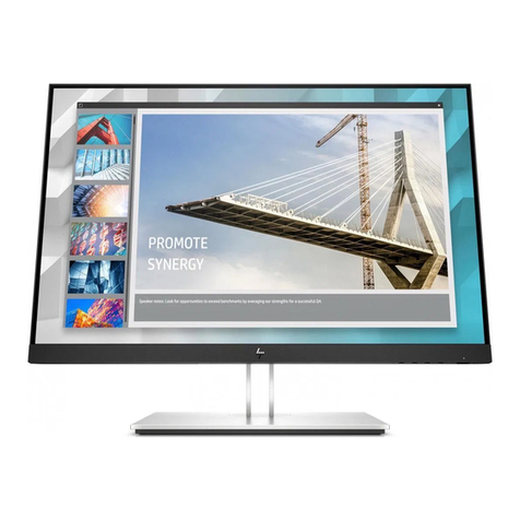
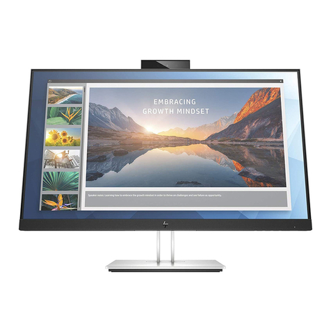
HP E24mv G4 FHD Conferencing Monitor
Purpose: The document is intended for use by end-of-life recyclers or treatment facilities. It provides the basic instructions for the
disassembly of HP Inc. products to remove components and materials requiring selective treatment, as defined by EU directive
2012/19/EC, Waste Electrical and Electronic Equipment (WEEE).
NOTE: Recyclers should sort plastic materials into resin streams for recycling based on the ISO 11469 plastic marking code on the
plastic part. For any questions on plastic marking or identification of location of parts or components requiring selective treatment,
please contact HP’s Sustainability Contact.
1.0 Items Requiring Selective Treatment
1.1 Items listed below are classified as requiring selective treatment. An “X” in the list of components and parts indicates the product
contains the component or part requiring selective treatment
Item Description Components and parts requiring selective
treatments
Quantity of
items
included in
product
Printed Circuit Boards (PCB) or Printed Circuit
Assemblies (PCA) with a surface greater than 10 sq cm
☒Main board (MB) PCB
☐Solid state drive (SSD) PCB
☐Wireless WAN module (WWAN) PCB
☐Touch module PCB
☒Power supply PCB
☐External Keyboard (KB)
☐External Mouse
☒Others: _______Key Board & USB board&Audio
board______
5
Batteries, excluding Li-Ion batteries. This includes
standard alkaline, coin or button style batteries
☐RTC/CMOS battery
☐Others: _____________
0
Li-Ion batteries. Includes all Li-Ion batteries if more
than one is provided with the product (such as a
detachable notebook keyboard battery, etc.)
Li-ion battery(ies) are attached to the product by:
☐screws
☐snaps
☐adhesive
☐other. Explain
0
Mercury-containing components. For example,
mercury in lamps, display backlights, scanner lamps,
switches, batteries
0
Liquid Crystal Displays (LCD) with a surface greater
than 100 sq cm. Includes background illuminated
displays with gas discharge lamps
☒Panel LCD
1
EL-MF877-00 Page 2
Template Revision D
last updated May-2022
HP Inc. instructions for this template are available at EL-MF877-01
Item Description Components and parts requiring selective
treatments
Quantity of
items
included in
product
Cathode Ray Tubes (CRT)
0
Capacitors / condensers (Containing PCB/PCT)
0
Electrolytic Capacitors / Condensers measuring greater
than 2.5 cm in diameter or height
☒Power Supply capacitor(s) or condenser(s)
1
External electrical cables and cords
☒AC power cord
☐Audio, video or data cables
☒Other: ___ HDMI cable/DP cable/USB 3.0 A-B cable
______
4
Gas Discharge Lamps
0
Plastics containing Brominated Flame Retardants (not
including external electrical cables and cords, PCBs or
PCAs already listed as a separate item above)
0
Components and parts containing toner and ink,
including liquids, semi-liquids (gel/paste) and toner.
Include the cartridges, print heads, tubes, vent
chambers, and service stations.
0
Components and waste containing asbestos 0
Components, parts and materials containing
refractory ceramic fibers
0
Components, parts and materials containing
radioactive substances
0
Components containing chlorofluorocarbons (CFC),
hydrochlorofluorocarbons (HCFC) or
hydrofluorocarbons (HFC), hydrocarbons (HC)
0
2.0 Tools Required
List the type and size of the tools that would typically be used to disassemble the product to a point where components and
materials requiring selective treatment can be removed.
Tool Description
Tool Size (if
applicable)
Screwdriver
RUBICON
NO-107 NO.2
HEX header screwdriver
5.0mm 9400-
M5 Pro'sKit
Heatgun
N/A
Suction cup
N/A
3.0 Product Disassembly Process
3.1 List the basic steps that should typically be followed to remove components and materials requiring selective treatment including
the required steps to remove the external enclosure.
1. Lay the monitor on a flat, soft and clean surface.
EL-MF877-00 Page 3
Template Revision D
last updated May-2022
HP Inc. instructions for this template are available at EL-MF877-01
2. Push the button to remove the stand-base assy.
3. Remove the screws to remove the Rear cover.
4. Remove the tapes and disconnect the connectors
5. Remove the screws to remove the WEBCAM MODULE
6. Remove the AUDIO /USB /KEY BOARD
7. Remove the screws to remove the Latch
8. Remove the tapes and Disconnect the pins and remove the speakers
9. Remove the screws on mid-frame
10. Remove the mylar on PCBA Board. Remove the main board and power board
11. Remove the connectors and Remove the screw to remove the Connector Board
12. Remove the screws to remove the Webcam holder_B other
13. Remove the Webcam Module.
3.2 Location of components requiring selective treatment. The photos and/or graphics below identify the location of the parts or
components requiring selective treatment within the main unit. For End-of-Life product disassembly instructions of external
accessories including external power supply (EPS), external keyboard (KB) external mouse and external cables and cords, refer to the
following URL: End-of-Life Product Disassembly Instructions (hp.com)
1. Precaution
Please read the precautions as follows to prevent any damages to the LCD Monitor.
Make sure all power connection is removed. Be sure that the LCD Monitor is in power off status.
Prepare soft cloth and sponge as
working platform to place LCD
monitor horizontally.
EL-MF877-00 Page 4
Template Revision D
last updated May-2022
HP Inc. instructions for this template are available at EL-MF877-01
Hold LCD by the side carefully and
DON’T touch or press panel
directly.
2. Appropriate tools
Select the appropriate tools for disassembly and re-assembly.
Screwdriver
RUBICON
NO-107 NO.2
HEX header screwdriver
Pro’sKit
5.0mm 9400-M5 Pro'sKit
3. Step
Step
Figure
Description
EL-MF877-00 Page 5
Template Revision D
last updated May-2022
HP Inc. instructions for this template are available at EL-MF877-01
Preparation
Lay the monitor
on a flat, soft
and clean
surface.
Remove the
Stand-base
Ass’y
Push the button
the remove the
stand-base
ass’y
EL-MF877-00 Page 6
Template Revision D
last updated May-2022
HP Inc. instructions for this template are available at EL-MF877-01
Remove the
Rear cover
Use the
screwdriver to
remove the
screws from the
Rear cover.
EL-MF877-00 Page 7
Template Revision D
last updated May-2022
HP Inc. instructions for this template are available at EL-MF877-01
Remove the
tapes and
disconnect the
connectors,
remove the
speakers
Remove the
tapes and
disconnect the
connectors,
remove the
speakers.
EL-MF877-00 Page 8
Template Revision D
last updated May-2022
HP Inc. instructions for this template are available at EL-MF877-01
Remove the
screws
Use the
screwdriver to
remove the
13pcs screws
from the
middleframe.
EL-MF877-00 Page 9
Template Revision D
last updated May-2022
HP Inc. instructions for this template are available at EL-MF877-01
Remove the
middle frame
and the panel
Remove the
middle frame
and the panel
Remove the
Mylar
Remove the
Mylar
EL-MF877-00 Page 10
Template Revision D
last updated May-2022
HP Inc. instructions for this template are available at EL-MF877-01
Remove the
main board and
power board
1. Use the
screwdriver to
remove the 8
pcs screws
from the main
board and
power board
2. Use the HEX
header
screwdriver to
remove the two
screws from the
main board.
Power Board
Main Board
EL-MF877-00 Page 11
Template Revision D
last updated May-2022
HP Inc. instructions for this template are available at EL-MF877-01
Remove the
connectors
Remove the
connect pins
Capacitors greater than
2.5cm in diameter or
height
EL-MF877-00 Page 12
Template Revision D
last updated May-2022
HP Inc. instructions for this template are available at EL-MF877-01
The Mainframe
The mainframe
Remove the
tapes
Remove the
tapes
Remove the
screws to
remove the
Webcam Module
Use the
screwdrive to
remove the 4
pcs screws
from the
Webcam
Module.
Remove the
screw to remove
the Connector
Board
Use the
screwdrive to
remove the
screw from the
Connector
Board and
disconnect the
pin.
EL-MF877-00 Page 13
Template Revision D
last updated May-2022
HP Inc. instructions for this template are available at EL-MF877-01
Remove the
screw to remove
the key board
and Audio board
Use the
screwdrive to
remove the
screw from the
Audio board.
Remove the
key board.
Remove the
screw to remove
the key board
and USB board
Use the
screwdrive to
remove the
screw from the
USB board.
Remove the key
board.
Disconnect the
pins to remove
the boards
Disconnect the
pins to remove
the key
boards/USB
board/Audio
board
EL-MF877-00 Page 14
Template Revision D
last updated May-2022
HP Inc. instructions for this template are available at EL-MF877-01
The middle
frame
The middle
frame
The DECO Bezel
The DECO
Bezel

Other manuals for E24mv

1

Other HP Monitor manuals

HP L1745 User manual

HP

HP L1745 User manual

HP P244 Installation instructions

HP

HP P244 Installation instructions

HP 24es Assembly instructions

HP

HP 24es Assembly instructions

HP L1902 User manual

HP

HP L1902 User manual

HP Compaq R201 Assembly instructions

HP

HP Compaq R201 Assembly instructions

HP M22f Manual

HP

HP M22f Manual

HP 82913A User manual

HP

HP 82913A User manual

HP Ergo 1600 User manual

HP

HP Ergo 1600 User manual

HP 82912A User manual

HP

HP 82912A User manual

HP L1908wm - 19" LCD Monitor User instructions

HP

HP L1908wm - 19" LCD Monitor User instructions

HP V14 Installation instructions

HP

HP V14 Installation instructions

HP Presario CQ1569 User manual

HP

HP Presario CQ1569 User manual

HP L1706 User instructions

HP

HP L1706 User instructions

HP Compaq LE2202x User manual

HP

HP Compaq LE2202x User manual

HP HC241 Manual

HP

HP HC241 Manual

HP Compaq CV5500 User manual

HP

HP Compaq CV5500 User manual

HP 27m Installation instructions

HP

HP 27m Installation instructions

HP D5259A - Pavilion M70 - 17" CRT Display User manual

HP

HP D5259A - Pavilion M70 - 17" CRT Display User manual

HP P274 Installation instructions

HP

HP P274 Installation instructions

HP 24 Assembly instructions

HP

HP 24 Assembly instructions

HP 55HP User manual

HP

HP 55HP User manual

HP L1706 User instructions

HP

HP L1706 User instructions

HP L1740 User manual

HP

HP L1740 User manual

HP LD4235 User manual

HP

HP LD4235 User manual

Popular Monitor manuals by other brands

Furuno Mu 120c Operator's manual

Furuno

Furuno Mu 120c Operator's manual

Dukane ImagePro P42 user manual

Dukane

Dukane ImagePro P42 user manual

Wincor Nixdorf BA71-R operating manual

Wincor Nixdorf

Wincor Nixdorf BA71-R operating manual

Clarion VMA 5894  VMA5894 VMA5894 Owner's installation guide

Clarion

Clarion VMA 5894 VMA5894 VMA5894 Owner's installation guide

Philips 221TE2LB/00 Service manual

Philips

Philips 221TE2LB/00 Service manual

Eonon 9'' TFT LCD COLOR MONITOR operating instructions

Eonon

Eonon 9'' TFT LCD COLOR MONITOR operating instructions

Panasonic BTLH2550E - LCD VIDEO MONITOR operating instructions

Panasonic

Panasonic BTLH2550E - LCD VIDEO MONITOR operating instructions

Fermax VEO DUOX quick start guide

Fermax

Fermax VEO DUOX quick start guide

Samsung S27E332H user manual

Samsung

Samsung S27E332H user manual

Acer B193 user guide

Acer

Acer B193 user guide

AOC U2868PQU user manual

AOC

AOC U2868PQU user manual

Philips 4CM2299 operating instructions

Philips

Philips 4CM2299 operating instructions

Acer CB272U Service manual

Acer

Acer CB272U Service manual

Elvox wide TOUCH 7311 operating instructions

Elvox

Elvox wide TOUCH 7311 operating instructions

Sony SDM-HS74 Service manual

Sony

Sony SDM-HS74 Service manual

Acer 193199140210 user guide

Acer

Acer 193199140210 user guide

Primeview 40" user guide

Primeview

Primeview 40" user guide

Alienware OptX AW2310 Setting up

Alienware

Alienware OptX AW2310 Setting up

manuals.online logo
manuals.online logoBrands
  • About & Mission
  • Contact us
  • Privacy Policy
  • Terms and Conditions

Copyright 2025 Manuals.Online. All Rights Reserved.