HPF HPFUV User manual

Page 1of 21
Ultra Violet Germicidal Disinfection
Whole House Filtration
System with UV in
SS Enclosure
Contents
Technical Overview.................................................................................................................................................................. 2
I. Important Notes................................................................................................................................................................ 2
II. UV Specifications.............................................................................................................................................................. 2
III.WARNING .......................................................................................................................................................................... 3
IV. Before You Purchase/Open ............................................................................................................................................ 3
V. Before You Begin Installation.......................................................................................................................................... 4
VI. What is Standard Filtration............................................................................................................................................ 4
VII. Product Application: What is UV light and How Does It Work?.................................................................................... 4
IX. Installation with other Systems ..................................................................................................................................... 5
Installation Introduction.......................................................................................................................................................... 5
I. Site Preparation................................................................................................................................................................ 5
II. Stainless Steel Enclosure................................................................................................................................................. 6
III. System Installation & Mounting ..................................................................................................................................... 6
IV. Installing Connections .................................................................................................................................................... 6
V. Filter Protection................................................................................................................................................................ 6
VI. Pressure Gauge Installation........................................................................................................................................... 7
VII. Cartridge Installation.................................................................................................................................................... 7
Ultraviolet System Installation ............................................................................................................................................... 8
I. Thimble (Quartz Tube) Installation.................................................................................................................................. 8
II. UV Lamp Installation ..................................................................................................................................................... 10
III. Ballast Operation.......................................................................................................................................................... 11
System Start Up & Operation ................................................................................................................................................ 13
I. Plumber Commissioning ................................................................................................................................................ 13
II. Turning the System On/Off............................................................................................................................................ 13
Maintenance........................................................................................................................................................................... 13
I. Stainless Steel Enclosure + Filter Housing Replacement Parts.................................................................................... 13
II. Replacement Cartridges................................................................................................................................................ 13
III. Testing Filters................................................................................................................................................................ 14

Page 2of 21
IV. UV System Replacement Parts & Maintenance.......................................................................................................... 14
V. Lamp Replacement........................................................................................................................................................ 14
VI. Thimble (Quartz Tube) Replacement .......................................................................................................................... 14
Troubleshooting..................................................................................................................................................................... 16
Warranty ................................................................................................................................................................................. 20
I. General Warranty............................................................................................................................................................ 20
II. Qualification for Warranty............................................................................................................................................. 20
III. Exclusions ...................................................................................................................................................................... 20
IV. Extended Warranty ....................................................................................................................................................... 20
Extended Warranty Qualification ........................................................................................................................... 21
Pro-Rata & Consumable Warranty.......................................................................................................................... 21
Definitions............................................................................................................................................................... 21
Technical Overview
I. Important Notes
For correct operation of this appliance, it is essential to observe the manufacturer’s instructions.
Installation must be carried out by a qualified plumber or authorised technician to comply with Australian Plumbing
Codes. This filter system is certified to WaterMark Standards AS/NZS 3497 Under the Certificate number 23247.
WaterMark certification is the level of certification required by law for a licensed plumber in Australia to install a
water filter system.
This system contains electrical components and plumbing components. Use caution and if leaking occurs,
turn the power off immediately before conducting maintenance or repair to the system. Installation must be
carried out by a qualified plumber or authorised technician. The power supply should always be plugged
directly into a surge protector. Standard power supplies are NOT water proof and must be installed out of
the elements to avoid water damage.
This appliance is not intended for use by persons (including children) with reduced physical, sensory, or mental
capabilities, or lack of experience and knowledge, unless they have been given supervision or instruction concerning
use of the appliance by a person responsible for their safety.
Children should be supervised to ensure that they do not play with the appliance.
If the supply cord is damaged, it must be replaced by a special cord or assembly available from the manufacturer or
its service agent.
II. UV Specifications
Flow Rate @ 30mJ/cm²
105L/Min
Flow Rate @ 40mJ/cm²
75L/Min
Voltage
230V – 240V (Ballast), 60V (Lamp)
Chamber Material
304SS
Max pressure
700 kpa
Operating Pressure
500 kPa
Lamp Power
48W HO
System Dimensions
600mm (Width) x 220mm (Depth) x 875mm (Height)
Port Size 1” BSP Female

Page 3of 21
III.WARNING
This appliance must be installed directly into a single socket surge protector before being
connected to a 240V 10A General Power Outlet (Power Point). It must be a surge protector
- Circuit Breakers and Residual Current Devices (RCDs) are not suitable substitutes as
they do not protect the unit from power surges.
Danger: Dangerous electrical voltage is present inside the power supply box & chamber. These instructions must be
followed closely to prevent serious personal injury. Ensure eye protection is worn when servicing and installing this
unit to protect from harmful UV-C Radiation. This radiation can be harmful to eyes and skin, UV lamps should only be
used when properly installed in the irradiation chamber. The UV lamp must not be operated outside the chamber.
•This unit must be used only for its intended purpose as described by the manufacturer.
•This unit must be installed in accordance with this manual.
•The unit must be unplugged when not in use, before fitting or removing any parts.
•The unit must be electrically isolated before Maintenance, Cleaning or Lamp Replacement.
•The System will need to be de-pressurised before maintenance.
•The UV lamp is designed for continuous usage to reach full disinfection capacity. Frequently turning the
system on/off will reduce the lamp’s effectiveness and may cause the lamp to fail.
•Do not attempt to use this sterilizer if it has been submerged. If this occurs, turn main power off, unplug the
electrical connection and then retrieve the unit if safe to do so.
•Do not operate this unit if it has a damaged cord or plug, if it is malfunctioning or if it has been dropped or
been damaged in any manner.
•Always disconnect the water supply and completely drain the water purifier if it will be subjected to
temperatures below freezing for extended periods of time.
Overheating: For long periods of no flow the power should be turned OFF. If the system is used intermittently, it is
recommended to install a Thermal Relief Valve (TRV), which can be purchased separately. Excessive build-up of
temperature in the chamber may cause the O-ring to deform and fail, causing leakage which can blow the
lamp/power supply causing damage or personal injury. Installing a UV system without a TRV may voidwarranty –
check the Warranty details for further clarification.
IV. Before You Purchase/Open
The system requires specific working conditions to be met before installation, some general guidelines* are listed
below. If these conditions are not met, the system may not be suitable for the application and may not function as
specified.These systems are designed for use in home applications on Main Water or Tank Water. For applications
where raw water supplies are used (E.g. Bore, Dam, Creek) please contact the manufacturer for technical assistance
to determine if your application is suitable for these systems.
Feed Water Conditions
Min
Max
Inlet Pressure
175 kPa
700 kPa
Temperature
0.5°C
38°C
pH Level
2
11
TDS
0 mg/L
2,000 mg/L
Iron
0 mg/L
0.3 mg/L
Manganese
0 mg/L
0.01 mg/L
Hardness
0 mg/L
200 mg/L
Turbidity
0 NTU
1 NTU
UV Transmittance
>75%
-

Page 4of 21
V. Before You Begin Installation
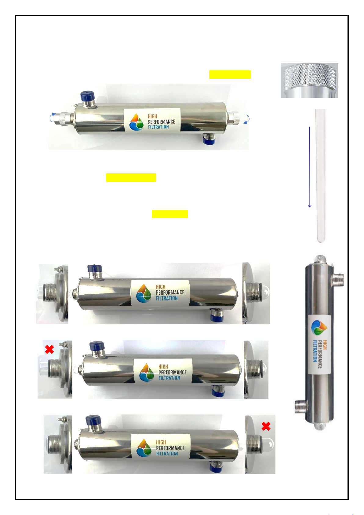
The HPF-UV systems come pre-assembled on the bracket with centre joiners installed. These units are batch tested to
ensure there are no leaks. Due to transit, fittings and other components may be loosened or damaged –
ensure the system is inspected for damages prior to employing a plumber for installation.
•To ensure full germicidal protection, tanks should be treated with HydroSil-ULTRA (Hydrogen Peroxide Water
Sanitiser) before the HPF-UV system is installed. After dosing, run water throughout the house (open each
tap) and this will sanitise the plumbing within your house. This is required as UV systems are a point of
contact sanitiser which do not have any residual effect (i.e., they only kill bacteria when flowing through the
UV; UV radiation does not stay in the water as is moves throughout your house). Once this is completed, you
can begin installation. The procedure for sanitising the plumbing system is readily accomplished as follows:
1. Shut off the upstream water supply that feeds water into the reactor chamber and depressurise
water system (if applicable).
2. Remove the pre-filter cartridge and add the recommended dosage of Hydrosil Ultra as per
manufacturer’s instructions. (Available at your local re sellers)
3. Verify that the UV System is connected to the AC power voltage and operating properly.
4. Open all faucets, fixtures and appliances and allow cold water to rununtil you are satisfied that the
Hydrosil has reached every outlet. Shut the faucets off and leave the solution sit for a period of 30-60
minutes. You must ensure that all taps, including outside faucets, dishwashers, shower heads,
washing machines, toilets, hot water heater, etc., andany device or appliance attached to the
plumbing system pass the treated water.
5. Open the upstream water supply and reinstall any filter cartridges (if applicable) into the filter and
then you can run the system as per instructions.
6. It is important to remember that in the event that a UV is briefly shut down for routine cleaning or
during power interruptions where water could have passed through the system, the aforementioned
pipe disinfection procedure must be conducted again.
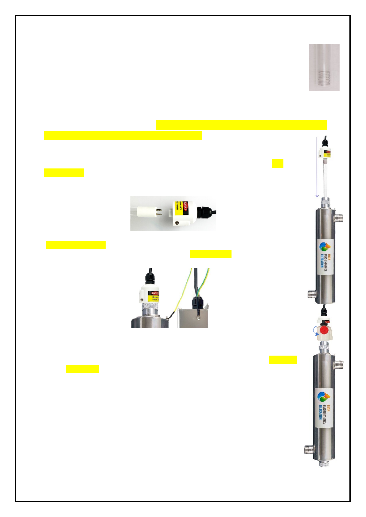
•The UV system should be installed after a filter on the return line. This helps ensure that the water is clear of
debris and impurities that could inhibit the disinfection process and increase the risk of damage toglass
internals. The UV can be installed before a filter, however, it will take longer to work.
•If water pressure is above 12bar, add a PRESSURE REGULATING VALVE on the inlet side of the equipment to
protect the Thimble.
•If water demand can possibly exceed the rated flow, install a flow restrictor on the inlet side of the device.
VI. What is Standard Filtration
Standard Filtration generally refers to systems designed to remove dirt/sediment & chemicals (such as chlorine) from
drinking water. Standard Filtration and UV systems are NOT designed to remove Fluoride or other dissolved salts or
minerals from water. Such units are generally simple to install/run, have a low cost to maintain and help improve the
taste of the water whilst removing common impurities.
VII. Product Application: What is UV light and How Does It Work?
UV water disinfection systems are a popular, highly effective, and easy to use way to protect your family from water-
borne living organisms. It is trusted by thousands of people worldwide and is widely used in homes, offices,
commercial and industrial applications.
Advantages of UV include:
•Effectiveness: Application of UV light triggers a reaction almost instantly; more effective than chlorination and other
water disinfection systems on a wide range of pathogens.
•Safe and chemical-free: UV light does not result in the creation of harmful disinfection by-products; UV does not alter
water chemistry and its constituents, such as pH, taste, odour, colour etc.
•Low Cost: Capital cost is low and operating cost is low compared to alternative disinfection methods.
•Simple to install and operate: no moving parts to wear out; installation flexibility.

Page 5of 21
CAUTION: UV light is not visible to the human eye, but is harmful to eyes and skin.
UV light is comprised of electromagnetic radiation of wavelengths ranging from 100 to 400 nanometers (nm). The UV
spectrum is divided into four regions, which are designated vacuum UV, UV-A, UV-B, and UV-C. UV-C. Short-wave
ultraviolet occurs between 200-280nm and the optimum UV germicidal action is at 265nm. It has strong disinfection
ability to kill microorganisms by altering or disrupting their DNA or RNA without the need for chemicals.
IX. Installation with other Systems
It is common for UV Systems to be installed alongside other additional filtration systems for different applications.
Below are some example scenarios. NOTE: These are just guidelines and may be different depending on the
requirements of the job. Check with the client or supplier as to which type of installation order is required for non-
standard installations.
Sediment & Carbon Filters: Sediment filters can reduce sediment as fine as 1 Micron, whilst Carbon Block filters can
reduce sediment as fine as 0.5 Micron. Carbon Blocks are also particularly effective as adsorbing taste and odour
molecules, and can provide a slight improvement in water clarity.
Calcite Filter: Calcite filters are usually installed on Rainwater Systems to counteract the pH of acidic rainwater
which usually causes green/blue staining in the water or on fixtures. The calcite filter isusually installed as stage 1 as
it is a back washable media vessel, followed by the Big Blue components of the HPF-UV System.
Water Softener: Water softeners are common on both mains water and also bore water installations. For bore water
installations it is best to check with the supplier as to the installation position and any other requirements such as
flow controllers and float switches. The most common bore water installation will go in order of Bore Softener
Tank Calcite Filter HPF-UV House
Installation Introduction
I. Site Preparation
The HPFUV System will need to be installed on the water line between the water supply and your house. Ideally if you
can find where the cold water enters the building or tees off to the HWS. Either way, you will need access to modify
the pipe work to install the system in place.
Allow enough room to install a bypass for the filtration system. If something goes wrong with the system, or during
maintenance you can still get a water supply to the house. Below is an example of a bypass installation.

Page 6of 21
The HPF-UV System is weather resistant, however, where possible it is best for the longevity of the system
to install the unit undercover, if possible, to shield it from direct sunlight and weather extremes such as
rain, storms, and frost.
II. Stainless Steel Enclosure
The Stainless-Steel Enclosure & Frame of the HPF-UV system is proudly Australian Made & Owned.
Manufactured locally here in SE QLD. It features a robust stainless-steel frame & thick heavy duty
mounting plate for the filtration. The front cover is a sleek & stylish brushed chrome finish with premium laser etching
rather than plastic stickers/labelling to blend in with a more modern and upmarket style home. The top cover has a
toughened glass viewing window for easy monitoring of the UV system and the pressure gauges. Durable automotive
grade 3M™ compressed foam tape lining fixed to the joins to reduce metal on metal contact and reduces the chance
of water and dust from entering the top section. Toolless fixing screws are used to mount the front cover and top
cover in place which can easily be removed by hand OR a flat head screwdriver.
III. System Installation & Mounting
NOTE: All units are quality tested from the factory. When you receive your system, open package to check all
components are inside (Reactor Chamber, UV Lamp, Thimble (Quartz Tube), O-ring, Electronic Ballast and Support).
Check the rated working pressure for operation recommendations. Install sterilizer equipment in a readily accessible
and well-lit location to facilitate inspection and maintenance. On all units allow sufficient head-space to change the
UV Lamp and Thimble (typically leave a maintenance space equal to the overall UV system length) and other parts.
The system is constructed from Stainless Steel and has two keyhole mounts at the rear of the top plate for mounting
the unit. Allow enough space on either side for the plumbing connections and ensure there is enough space in front of
the unit to allow easy removal of the front/top covers and for maintenance. Also allow at least 500mm height
clearance for the UV lamp installation & maintenance. The mounting location will require a 10A GPO within ~1.5m
from the left side of the system for the UV power supply. If mounting on an uneven surface (such as rough brick), it is
recommended to install a spacer behind the mounting holes, so the unit is sitting slightly off the wall to allow easier
installation & removal of the top cover.
IV. Installing Connections
The HPF-UV system has a standard 1” Female BSP port for the inlet connection into the stage 1 Big Blue filter housing.
The outlet point from the UV system has an internal and external thread to choose from depending on the installation
requirements (i.e. 1” BSP male or ¾” BSP female).
DO NOT use any type of liquid thread sealant as this will cause the cap to split shortly after it cures –
warranty will not cover this.
Thread tape is the only form of sealing material permitted for use on these housings. Alternatively, you can
also use a suitable 1” BSP fitting with an O-ring for sealing.
V. Filter Protection
If there is no Pressure Limiting Device (PLV) installed on the main line incoming to the house to limit the
water pressure to 500 kPa, you will need to install one prior to the UV and any pre-installed filtration
system to reduce the pressure in compliance with Australian Plumbing Codes & HPF Warranty. Failure to do
so may cause excessive pressure & potentially damage the system.
It is recommended that an anti-water hammer device is installed on the house to dampen water hammer commonly
caused by washing machines. It is best to install these devices at the point of hammer such as on the cold-water line
at the washing machine or dishwasher.

Page 7of 21
VI. Pressure Gauge Installation
The HPF-UV system is supplied pre-fit with gauges, if the gauges are to be removed or replaced, follow the below.
Kit Contains: Opening Spanner, Pressure Gauges (If applicable), Gauge Port Bungs, O-Rings
Install with Gauge Plugs: The housings are supplied with a thin o-ring is a zip-lock bag. Install this o-ring into the
gauge port then screw in the gauge plugs firmly without thread tape.
Install with Pressure Gauges: When installing pressure gauges, use the thin o-ring supplied in the zip-lock bag, the
O-ring is to go in the port at the bottom – NOT around the thread of the gauge.
Firmly hand tighten the gauge without the use of thread tape – Do not overtighten the gauge.
NOTE: If there is no reading on the pressure gauge, it is likely that the gauge is too tight – causing the o-ring
to obstruct the hole on the gauge.
If the o-rings do not provide an adequate seal, you are permitted to remove them and use 6 to 8 wraps of white
plumber’s tape. Excess thread tape or thread glue/sealant will cause the port to split.
VII. Cartridge Installation
Cartridges should be installed in order of: Pleated Before Polyspun, Polyspun Before Carbon, Highest Micron Before
Lowest Micron. As an example, a common filter set would be a 5uM Polyspun Sediment Filter, followed by a 5uM Silver
Carbon. You would install them in that order as per the above guideline.
Cartridges will need to have the outer plastic shrink wrapping removed before being installed. Maintain minimal
contact with the surface of the carbon filter, handle by the end caps only to avoid contamination as carbon will
absorb smells and oils from the skin. NOTE: Cartridges may be supplied already inside the housings for
transport, however they will still be wrapped in their original wrapping as per regulatory guidelines. MAKE
SURE TO REMOVE THE WRAPPERS BEFORE SCREWING UP THE SUMPS!
Gently lower the cartridge into the blue sump and locate the filter so the stem in the bottom of the sump inserts into
the centre hole of the cartridge. Do not drop the filter in as this centre stem may break the plastic caps of the filters.
Once the filter is located, screw the sump into the cap (in a vertical position). It can help to wobble the sump to help
the filter locate into the guide lugs in the top of the cap.
The caps should screw up rather smoothly with little resistance so it is usually suitable to firmly hand tighten the
housings. If you encounter resistance before the housing is more than ¾ tightened you may not have the cartridge
aligned with the guide lugs; remove the sump and line it up correctly before tightening. An opening spanner is
provided with these systems and is only required for installation if hand tightening is not easily achieved or if slight
leaking occurs. It is important not to overtighten the housings as this can lead to excessive stress on the cap thread
which may cause damage to the housing long term. The spanner can be used to help unscrew the housing when filter
changes are required as the housings are usually more difficult to unscrew over time being installed.

Page 8of 21
Ultraviolet System Installation
I. Thimble (Quartz Tube) Installation
Due to the fragile nature of the thimble, care must be taken when handling and installing the thimble and lamp. The
below steps are for horizontal installations.
1. Remove the knurled nuts from either end of the UV chamber (shown below).
2. Wearing clean gloves or handling with a micro-fibre cloth, remove the thimble from the
packaging and check for any marks or blemishes. Insert the glass thimble into the
chamber from the top (see picture right). DO NOT DROP THE THIMBLE INSIDE THE
CHAMBER AS IT WILL SHATTER.
3. Allow equal parts of the thimble to be exposed from each end of the chamber and slide
the O-Rings over each end of the glass (shown below). Be careful not to drop the glass
at this point. Once the O-rings are seated, this will assist in holding the glass in place. It
is recommended to put something soft underneath the system just in case the glass
does slip through, as this it may help prevent the glass from breaking if dropped.
Balanced (Ideal) Thimble Position
Thimble Seated too High
Thimble Seated too Deeply
Knurled Nut

Page 9of 21
4. When the O-rings are seated, firstly loosely install the bottom nut and then the top nut until you feel
resistance. Simultaneously tighten (by hand) the top and the bottom nut equally to keep the thimble centred
in the chamber. Caution: Do not apply any thread tape, grease, or sealant as this will void the
warranty. Overtightening the nuts may cause the thimble to crack.
5. You can look through the open end of the nut to see if the o-ring is seated correctly or feel this with your
fingers (shown below). There should be a slight gap between the end edge of the thimble and the recessed
stop-end of the knurled nut.
6. If you see that the thimble is hitting the stop end of the top nut (i.e. glass on metal), stop tightening the nuts
because it is likely that the bottom nut has caused the thimble to shift off centre. You will need to loosen off
the bottom nut and push the glass back down before continuing with tightening. If you experience issues
with this, please contact the distributor or manufacturer for assistance.
7. When following the next commissioning steps, take the time to check the chamber for leaks once it is
pressurised. If a leak occurs, the knurled nuts may need to be tightened slightly. A gripping tool can be used
if required if the stop-end is not in contact with the glass. The thimble should be bone dry before the UV lamp
is installed. It is extremely important that there are no slow leaks, as over time, these will fill up the thimble
with water and cause a short in the lamp, which can result in injury or damage to the lamp & ballast.
NOTE: Damage caused by leaking or defective installation is not covered under warranty.

Page 10 of 21
II. UV Lamp Installation
Once the chamber has been pressure tested and there are no water leaks, the lamp can be installed. It is usually
recommended to complete step 1 to 4 of I. Plumber Commissioning (below)before installing the lamp.
1. Drop the spring into the thimble chamber. The spring should sit at the bottom of the thimble.
This prevents the UV lamp from falling/hitting the bottom of the glass, and keeps the lamp in
the correct position for the power connection.
2. Remove the lamp from its protective wrapping & inspect for damages. Before the lamp is installed, the
chamber, thimble and surrounding plumbing must be dry and free from water or leaks. Plug the ballast
(power supply) into a certified single socket surge protector, then into a 240V 10A GPO. Ensure the ballast
(power supply) is turned OFF at the wall. Note: No warranty will be covered for a blown lamp if the
ballast is not plugged directly into a surge protector.
3. You will need to connect the ballast connection to the lamp prior to lowering the lamp into the
thimble. Firmly hold the white cap of the UV lamp and the connection of the Ballast (see
picture below), then push (wiggle) the power supply connection onto the UV lamp pins. NOTE:
There is a long and short side of the pins so they will only go into the power supply one way.
Ensure the connection is firm and plugged in all the way.
4. Lower the lamp carefully down into the thimble until the lamp makes contact with the spring
(as shown to the right). Then, gently slide/wiggle the white cap over the knurled nut.
5. Connect the Green/Yellow earth wire to the small nut (per the below) and finger tighten the
nut over it to hold it in place.
6. At this point the lamp should be tested briefly to ensure it is working and the connection is
sound. Use appropriate Safety Eyewear for this step.
a. You can check that the lamp has illuminated by unscrewing the RED plug on the
White UV Connection Cap, or by carefully lifting the White Cap/UV Tube up (as shown
to the right).
b. Keep your hands clear of the system and turn on the power for 5 seconds to allow the
lamp to illuminate. Do not look directly at the lamp without eye protection.
c. Confirm that the lamp lights up correctly, and the ballast is showing a green light to
signify that the lamp is running correctly.
d. Replace the red plug or slide the white cap back over the knurled nut.
7. When you are ready to start 24/7 UV Sanitation, turn on the power supply and leave it on.
a. If there is a green light (per Ballast Operation - Working Conditions), everything is
running correctly. If not, turn the power off, check for leaks and refer to Ballast
Operation/Troubleshooting to diagnose the issue, or contact the supplier.

Page 11 of 21
III. Ballast Operation
This appliance must be installed directly into a single socket surge protector before being
connected to a 240V 10A General Power Outlet (Power Point). It must be a surge protector
- Circuit Breakers and Residual Current Devices (RCDs) are not suitable substitutes as
they do not protect the unit from power surges.
To guarantee user safety, this ballast features complete control and protection functions which are caused by.
1. UV Lamp exceeding life cycle (365 Days).
2. UV Lamp Failure.
3. Working beyond rated voltage and load.
This ballast is designed to work with germicidal UV lamps. Do not mistake the input/output wire to avoid ballast
failure.
•Ensure the voltage is within the specification of the ballast.
•Match the UV lamp with the power output of the ballast.
•Ensure the connections (plugs) are fitted correctly. Connect (screw) the
earth wire to the lug on the bottom of ballast (power source) as shown
(picture to the right). The earth wire must be affixed securely.
WORKING CONDITIONS:
The Lamp and Ballast are working correctly when the Green LED Indicator Light shows:
Display Screen - Press the “SELECT” button (for 2 seconds) to toggle between the Lamp Life Remaining
(Days) Default Display Screen and the Total Running (Days) Ballast Operation Time:
Lamp Life Remaining (Days) Default Display Screen - By default, the display screen will
show the lamp life, which counts down from 0365 to 0 days. Once the lamp life timer reaches 0,
the ballast will alarm to remind you to change the lamp.
Total Running (Days) Ballast Operation Time - Press the switch button (for up to 2 seconds)
to display the ballast operation time, which counts up from 0 to 9999 days. After 10 seconds the
screen will return to the default display.
LAMP REPLACEMENT DUE:
End of Lamp Life/UV Lamp Replacement Alarm: Once the Lamp Life Remaining timer reaches day
0, the digital display will show “A3”, the Red LED Error light will flash and an audible alarm will sound
(beeping). This indicates that it is time to replace your UV lamp.

Page 12 of 21
Temporary (7 Day) Alarm Pause/Cancellation: If the UV lamp cannot be immediately replaced,
you can temporarily pause the alarm by pressing the “SELECT” button for 5 seconds until the buzzer
sound stops. This will reset the Lamp Life Remaining display to 7 days, however, the display will
continue to show “A3” and the Red Error LED Light will still show. Once those 7 days are up (i.e. lamp
life reaches 0), the alarm will re-start. The ballast will provide 4x 7-Day alarm cancellations (for a
total of 28 days), after which point the alarm will alarm will not stop until the lamp is replaced.
Lamp Change/Ballast Reset:
Disconnect the power supply (See Part III: Installing New Lamp for detailed instructions on
changing the Lamp).
Remove the expired/failed lamp, and install the new lamp.
Press and hold the “SELECT” button for 15 seconds – at the 10 second mark the display will
show “RSET”, and after continuing to hold the button for a further 5 seconds, the display will
then flash “0365” and give off an audible beep. Release the button and the timer is
successfully reset.
ERROR/FAULT CONDITIONS:
Whilst it is usually the lamp that requires replacement, please refer to the below guidance along with the
Troubleshooting section of this guide to diagnose which element requires replacement.
×LAMP FAILURE: The Lamp has failed when the Red LED Indicator Light shows and/or the system is
alarming. Note: The Lamp Life will display “0”, but the Total Running (Days) count will continue.
BALLAST FAILURE: The display will be totally blank if the ballast has failed.
Ultraviolet Disinfection Water System are designed for continuous operation and frequent switching will reduce
Ultraviolet radiation and service life. Do not electrically cycle (i.e. do not turn on/off) the UV unit more than
THREE on/off cycles in a 24 hour period. If the water to the house in not going to be used for over 48 hours, the UV
system should be turned off to prevent overheating in the chamber. For periods of time over 1 week, the above also
applies, however we would suggest briefly flushing the system before use (allow the first few minutes to run down the
drain) specifically for drinking water. Allow 15 minutes for UV lamp to achieve full operating capacity before using the
water.

Page 13 of 21
System Start Up & Operation
I. Plumber Commissioning
When you are confident that the system is correctly installed, do the following steps to start up the system and
commence the flushing procedure.
1. Open a tap downstream from the system to allow air to bleed from the plumbing – if this is not easily
achievable disregard, just note that sputtering may occur more prevalently in the house until the air has
vented from the lines.
2. Close off the bypass and open the system valves to allow water to flow through the system, depress the red
button on top of the 1st housing until water comes out (to bleed the air), repeat for each housing inline.
3. The water coming out of the system will likely run cloudy or discoloured temporarily which is normal as this is
the fines coming off the carbon filter.
4. Shut off the downstream tap and allow the system to hold under static pressure and check for any leaks in
the filter plumbing connections.
5. While the filter is new, there may be some slight taste issues with the water (such as a metallic or ‘chemical
like’ taste. This is normal and is the reaction that activated carbon has with water when the filters are new.
Flushing the filters will help reduce the time until the water is back to normal taste. The metallic taste is
usually due to the high pH that is created due to this reaction, it is only temporary and is usually gone within
1 week from installation if not sooner.
II. Turning the System On/Off
This will depend on the style of bypass that is installed on the system. Refer to the above diagrams of a bypass in
service and bypass position.
If the water to the house in not going to be used for over 48 hours, it is recommended to turn the system into bypass
mode to avoid static pressure build up in the system. The UV system should also be turned off to prevent overheating
in the chamber. For periods of time over 1 week, the above also applies, however we would suggest briefly flushing
the system before use (allow the first few minutes to run down the drain) specifically for drinking water.
Maintenance
I. Stainless Steel Enclosure + Filter Housing Replacement Parts
There are generally no parts (excluding consumables) on the system that will require periodic replacement at regular
intervals. Below is a list of parts that may be applicable:
GT8-13G 20” x 4.5” Housing (Includes Cap)
GT8-11G-CAP BB Cap 1” Ports Suit GT8-11G + GT8-13G
GT19-35SC 1” Poly Nipple Joiner with O-Rings
GT16-3S 60mm Bottom Mount Pressure Gauge
GT19-127 ¼” Gauge Port Stopper
GT23-1LS BB O-Ring
GT17-2LS BB Opening Spanner
II. Replacement Cartridges
Cartridges have a varying life span but generally can be replaced under the following guidelines under normal
working conditions. For clean water supplies (commonly found in Metro locations on the E & SE coast of Australia),
filters should generally last up to 12 months. For harsher water conditions (high hardness, scale and TDS) commonly
found in rural areas or the North, West and South parts of Australia, filters may need to be changed every 6 months.
Filters that are exposed to raw water sources (rain, tank and bore water) may be more susceptible to clogging due to
sediment, and may be prone to bio-fouling (given that bacteria breeds on carbon ash).

Page 14 of 21
NOTE: Usage will also be a factor for filter changes – if your pressure begins to drop and the water slows down
through the filters it can be an indication that the filters are blocking and may be due for a replacement. These
guidelines are based on appropriately sized/quoted systems for the intended application. Systems purchased
without recommendation by the supplier may not perform to the above expectations.
III. Testing Filters
Differential pressure is a good test to determine if the filters are beginning to block and need replacement. When new
filters are installed, record the pressure on each gauge while the water is static (no flow) then again measure the
pressure with an outlet running (such as a shower). This will give you a baseline for static and flowing differential
pressure. There is no set rule as to when filters need replacing due to high differential loss, it more comes down to
personal preference. Filters should be replaced at least every 12 months.
IV. UV System Replacement Parts & Maintenance
The 48W lamp in this system is rated for an effective lifespan of 9000 hours (12 months). They are designed for
continuous running, not for intermittent operation. Lamp replacement is recommended every 9000 hours of
operation (approx. 365 days of constant runtime). After 9000 hours, the lamp may still light, but the UV intensity has
diminished. Cleaning of the Thimble is recommended once every 3-6 months with alcohol or a mild detergent.
Lamp replacement | Every 12 Months Replace Quarts Sleeve and O-Rings | Every 2 years
H7-90-Lamp 48W HO UV Lamp to suit H7-90-AT
H7-90-Thimble 470mm x 23mm OD Quartz Domed End Thimble
H7-90-OR 23mm OD O-Rings
Replacement Ballast
H7-90-PS HPF Electronic Ballast | 33W – 120W with Countdown Timer
V. Lamp Replacement
CAUTION: DO not touch the Lamp with your fingers. Handle by the ends only or wear soft non-abrasive heat-resistant
gloves to prevent any finger marks or burning.
1. No need to shut off water supply to UV system.
2. Disconnect main power source and allow the unit to power down for 30 seconds.
3. Remove the cover cap.
4. Withdraw wire with lamp carefully until approximately 2 inches of the lamp is exposed. Lamp case can be
very hot - be careful and do not drop the Lamp into the Thimble as both are easily broken.
5. Remove the 4-pin electrical socket from the lamp pins and keep a firm hold of the UV lamp.
6. Withdraw Lamp from Thimble carefully. Be sure to withdraw lamp straight out without angling until
completely clear of Thimble.
7. Follow up Lamp installation steps (UV Lamp Installation Steps 2 to step 6) to reinstall new lamp.
8. Reset the Ballast Timer per Ballast Operation Instructions “Lamp II. Replacement Due”.
VI. Thimble (Quartz Tube) Replacement
1. Turn off power.
2. Shut off water supply to UV system via inlet and outlet valves.
3. Drain the chamber.
4. Follow lamp replacement steps (above) to remove UV lamp.
5. Twist off nuts from reactor chamber.
6. Remove O-ring.
7. Remove quartz sleeve and withdraw it from chamber carefully.
8. If the thimble is broken, please follow next steps before reinstallation.

Page 15 of 21
a. Remove the input/output water pipe connector and withdraw the reactor chamber.
b. Carefully remove as much of the broken thimble as possible from both ends of the chamber.
c. To remove any fragments of glass, hold the system vertically and shake. The fragments will break
and drop out from threaded fitting of the chamber. Flush water through chamber, being careful to
remove all fragments from the interior of the chamber.
d. Carefully discard all pieces of the broken quartz sleeve.
9. Follow the installation steps (Thimble (Quartz Tube) Installation steps 1 to 7) to re-install the thimble into the
chamber.
10. Slowing restore water supply to UV system and check for leaks.
11. Follow the lamp installation steps (per the above) to reinstall new lamp.
12. Turn power back on.

Page 16 of 21
Troubleshooting
In order to maintain UV unit in optimum operation condition, if specific problems are detected during the routine
inspection, refer to applicable maintenance instructions for recommended repair procedure.
Problem
Possible Cause(s)
Solution
Twin 20” x 4.5” Filter System
Leaking from Centre
Joiners
1. Transit Damage
1. The system will need to be dismantled to fix the
leak. A plumber should be capable of fixing this;
however, it is best to contact the supplier
immediately.
Leaking from in/out Ports
1. Insufficient Thread Tape
2. Crack/Split
3. Incorrect Fitting
1. Remove existing tape and apply slightly more tape
– do not apply excessive amounts to avoid damage
to port.
2. Check the port for a hairline crack or split – if there
is one, the cap will need to be replaced, it is not
reparable.
3. The caps are 1” BSP and will require preferable a
1” BSPT male fitting.
Pressure Gauges Not
Showing a Reading
1. Obstruction
1. If there is no reading on the pressure gauge, it is
likely that the flat washer was not removed, or the
gauge is too tight – causing the washer to obstruct
the hole on the gauge. Loosen the gauge to correct
this.
Leaking from Gauge Port
1. Not tight enough
2. Missing O-Ring
3. Cracked port
1. There can be a fine line for these gauges to seal, if
required, remove the seals and use thread tape as
directed previously.
2. Install the O-ring into the port and try again
3. If there are any signs of damage to the port it may
need replacing with a new cap.
No Water Flow
1. Valve Position
2. Insufficient pressure
3. Damaged or Blocked Filter
4. Filter Wrapping
1. Check that the bypass and service valves are in the
correct position. Ensure the mains is also turned on.
2. Check the incoming water pressure and ensure it
meets the requirements of the selected filters. NOTE:
some filters require higher pressure to operate
(carbon filters).
3. Isolate each filter by process of elimination to
determine which filter is not allowing water to pass.
Check for damages. The filter may also need
replacing due to being blocked by some form of
contamination.
4. Ensure the filters are unwrapped before
installation.
High pH Reading
1. Carbon Filter
2. Insufficient Testing
Equipment
1. If you have a GAC or Block filter (Carbon), this will
naturally increase the pH of the water. pH is the
measure of Hydrogen in the water and this hydrogen
will vent off the water if you leave it to stand and the
pH will then drop back down to the normal level.
2. pH testing equipment can range from a cheap test
pen right up to lab grade equipment. Before coming
to a conclusion on pH issues, it is best to ensure the
equipment used to measure the pH of the filtered
water is of high standards and suitable for reading

Page 17 of 21
pH levels in lower EC water (i.e. The guy at the pool
shop is not going to cut it). We have access to high
quality testing equipment and frequently test our
units and conduct research. If you feel that there is
an issue with your pH, please contact us.
Strange taste to the water
(New System)
1. Residue
2. pH Alteration
3. Contamination
1. The filters are dry packed, the carbons, alkaline
filters will have ‘fines’ on them.
2. As previously stated, Activated Coconut carbon will
react with the water when new and will increase the
pH. People who are not accustomed to higher pH
water may notice a strange taste/sensation due to
the large variance of pH. Flushing the system will
help stabilise the pH from the system and also
allowing the water to stand before drinking can also
help allowing the water to ‘vent’ the pH
3. Bacterial contamination is highly unlikely, but not
impossible. If there is a strong ‘foul smell’ or organic
taste to the water, it is possible that there is some
form of contamination. Contact us straight away so
we can rectify (or diagnose) the problem if there is
one present.
Cloudy Water
1. Air in water
1. Air is common whenever the system is opened. This
will dissipate over time as the air flushes from the
system/plumbing.
Slimy Feeling Water
1. Activated Carbon Reaction
1. This is a common symptom with activated coconut
carbon. It gives the feeling of ultra-softened water
and can feel slimy and also cause soaps to have an
increased lather making it harder to rinse off. This is
only temporary and does not happen with every
installation.
Ultraviolet Sanitation System
Leaking from Chamber
1. O-Rings Not Seated
2. Knurled Nut too loose
3. Damaged Thimble
1. If there is any issue with the o-ring in the way they
are seated this will need to be fixed. Remove the
thimble and repeat steps 3 – 5
2. If the nut is not tight enough, the o-rings will not
have a good enough compression and will cause a
leak. Slightly tighten up the nut until a watertight
seal is achieved. It is better to tighten slightly at a
time to prevent overtightening.
3. If there is a crack or hole in the thimble, it will fill
from the inside out. Turn off the water, carefully
remove the thimble and replace with a new one. If
the thimble releases and shards of glass, this
chamber and downstream plumbing will need to be
thoroughly checked and any glass removed before
re-connection.
High Water Temperature
1. Low Flow Rate
1. If there are periods of low water usage or the
water is allowed to stand for long periods of time,
the water may be prone to heating up and may
become lukewarm or hot in extreme cases.
Generally, this only occurs on systems that have a

Page 18 of 21
2. Oversized System
short distance between the outlet and the point of
use. Whole house systems have a larger length of
cold plumbing pipes downstream.
2. If the system is too large for the application it is
likely that even with frequent water usage the water
does not get a chance to cool down effectively. If
there are significant fluctuations in usage or flow
rates, it is good practise to instal a thermal relief
valve sold separately on the outlet of the UV
chamber which can bleed water from the chamber
and keep temperatures below 56°C.
Hot SS Chamber
1. Low Usage
1. As Above, if the water is allowed to stand for
periods of time the chamber will heat up naturally.
This is normal, however if the heating is excessive to
the point where it is causing damage to the chamber
or surrounding fixtures, a thermal relief valve should
be fitted.
Ballast is alarming
1. Lamp Failure
2. Interrupted power supply
1. Usually if the ballast is alarming and showing a
red flashing status indicating light, the lamp has
failed, and it will require replacement. Before
replacing a lamp, it is best to check firstly for an
external cause for lamp failure, turn off the power
then check for water ingress from either rain, or
leaks or any signs of moisture or condensation in or
around the electricals. Due to the elevator
temperature of the lamp, high humidity may cause
condensate to form. If there are no signs of leaking,
check for signs of shorts or charring on the lamp
connection with the ballast. lastly inspect the tube to
see if there are any dark patches or if the filaments
are burnt out.
2. Sometimes the ballasts may trigger failure alarm
if the connection to the lamp is interrupted or
perhaps the connection is not solid enough. If the
above steps reveal no faults and the lamp is still
working, turn the power off for five minutes, check
connections and then turn it back on to see if the
fault clears.
No Lights on Ballast
1. Ballast failure
2. interrupted power supply
1. in the event of a large surge it is possible that the
ballast failed. This can also occur from shorts and
water ingress. cheque for signs of a short around the
lamp connexion end. The ballast will need to be
replaced. The UV lamp may also have blown at the
same time or could be the cause for the ballast
failure. for safety it is best to replace both the lamp
and ballast together. If it is within warranty. Please
contact the manufacturer for further instructions.
2. Check the wall socket with a different electrical
appliance to cheque if the GPO is functioning. Also
check your circuit breaker to see if any switches are
off.
Lamp is working but the
ballast is alarming
1. Faulty lamp
1. The lamp may be lighting up but not working at its
full capacity which may be caused by it not drawing

Page 19 of 21
2. Faulty ballast
enough power from the ballast. The lamp will
require replacement. Turn the system off, check
connections and turn back on to see if it fixes the
alarm.
2. The ballast could have a problem with the lamp
failure protection and may require replacement.
Turn the system off, check connections and turn back
on to see if it fixes the alarm.

Page 20 of 21
Warranty
I. General Warranty
Water Filter Systems¹ (Excluding consumables) Manufactured or Assembled² by High Performance Filtration (HPF)
are covered under a 12-month Warranty Against Defects (Manufacturer’s Warranty). This warrants the water filter
system to be free from defects in material and workmanship for a period of 12 months from date of sale.
If applicable, HPF may cover the return freight in the form of a re-imbursement after the system has been inspected
and confirmed it is a valid warranty claim.
HPF will not cover any labour charge incurred by the consumer for the replacement or repair of a product. The
warranty is strictly parts only for the parts supplied by HPF. This warranty only applies to the original consumer of the
product and is non-transferable. If you have purchased the system through a re-seller, please contact them to
facilitate the warranty on your behalf. All replaced or exchanged parts become the property of HPF.
HPF does not cover the workmanship of the plumber who originally installed the system. Responsibility for damages
that occur during installation fall with the plumber.
II. Qualification for Warranty
As per Australian Plumbing Codes, all filter systems must be installed by a qualified plumber. The consumer is
responsible for keeping record and proof of installation in the form of an invoice and/or receipt.
Filter systems must be maintained as per HPF recommendations³ including the use of replacement filters, fittings and
components supplied by HPF. Failure to maintain the filtration systems using HPF supplied/approved products may
void warranty.
The warranty only applies if the product was used and/or installed in accordance with the user guide and/or
installation instructions. This warranty is given in lieu of all other express or implied warranties and manufacturer
shall in no circumstance be held liable for damages consequential or otherwise or delays caused or faulty
manufacturing except as excluded by law.
Warranties need to be approved by HPF to ensure the product was not incorrectly used, installed, or claimed. False
and incorrect claims will be pursued at HPF’s discretion including chargeable inspection and transit costs incurred.
HPF does not take responsibility for retaining customer records, it is the consumer’s responsibility to retain all
invoices or proof of purchase from the original sale and ongoing maintenance records as proof of upkeep.
III. Exclusions
HPF Standard Warranty shall be void if the product sustains damage or failure resulting fromany of the following:
•If the system was not installed in accordance with the manufacturers instruction manual.
•If your system(s) fails to be maintained in accordance with recommended servicing and as per the
manufacturers operating instructions.
•Cross threading or damage to screws and/or threads
•Unauthorised or abnormal use or operation.
•Exposure to unsuitable environmental conditions*.
Warranty – Australia
This warranty is given by High Performance Filtration (Jacknel Pty Ltd ATF The J & N Family Trust). ABN 64 855 305
562 Located at 7/38 Jade Drive, Molendinar QLD 4214. Ph 07 5597 6142 & email info@hpfiltration.com.au
This warranty is provided in addition to other rights and remedies you have under law. Our products come with
guarantees which cannot be excluded under the Consumer Guarantees Act.
IV. Extended Warranty
The HPF-UV system is eligible for a conditional extended 4-year warranty (commencing no later than 12 months from
the sale date), to provide a total warranty period of 5 years. This extended warranty is subject to terms and
conditions outlined below. This extended warranty covers the below parts of the system.
•Ultraviolet Chamber
•20” Blue Housings & Centre Joiner
•PVC Manifold (Between UV and Filter System.
•HPF-UV Stainless Steel Frame & Enclosure
rev 1.0 | 30/09/2021
Table of contents