www.hitchcocksmotorcycles.com
Page
JO
Royal Enfield
"interceptor"
750
Series
11
Workshop Manual
21. Tappet Adjustment
The
tappet clearance
is
adjusted by means
of
a
screw in the
outer
end
of
the rocker. Access to the
adjusting screws
is
obtained
by removing the
covers
of
the rocker boxes.
The
correct clearances
are:-
Inlet .006 m
.,
Exhaust
.007 in.
These figures are for a
COLD
engine.
To
adjust
the clearance, loosei'i the
locknut
beneath the rocker
arm,
turn
the screw
and
re-
tighten the locknut.
The
adjustment
of
each valve should be made
with the corresponding valve in the
other
cylinder
fully open. This ensures
that
the
tappet
is
on
the
neutral position
of
the cam.
If
the heads
of
the adjusting screws are worn
they should be replaced.
22. Remornl
of
the
Camshafts
Remo
ve the timing cover (Subsection 19).
Remove the timing
chain
(Subsection 39).
Remove the rocker box covers
and
screw the
rocker
adjusting screws right back.
Unscrew the three screws holding each
of
the
timing side camshaft bearings. A hole
is
provided
in
the
camshaft
sprockets
and
this
can
be aligned
with each screw in
turn
, for access with a hexagon
wrench.
The
screws can be fully
undone
but
will
remain captive in the
cast
aluminium bearing.
Before removing
the
camshafts it
is
necessa1y
to
prevent
the tappets falling
through
their guides
when the shafts are
no
longer
holding
them up.
If
this
happens,
the
push
rods will come
out
of
engagement with the
rocker
arms
and make re-
pl;ctment
difficult. This can be prevented by
placing the
motor
cycle
on
its left side. With the
machine in this position,
rotate
the
camshaft
until
the
timing
marks
on
the
sprockets are
pointing
at
2
o'clock
for the inlet
and
I o'clock for the exhaust
when they
can
be
withdrawn
upwards complete
with sprockets
and
bearings.
If
the
machine has to
be moved before the shafts are replaced, it
is
essential
that
something
is
put
into
the
camshaft
tunnels to keep the tappets in place.
If
it
is
necessary to remove the sprockets from
the camshafts see Subsection 41.
23. Ignition Timing
The
contact
breakers are accessible after re-
moving the small oval cover. Owing to the provision
of
automatic
ignition advance, the
contact
breaker
is
always fully retarded when the engine
is
at
rest
or
is
being
turned
over slowly.
The
advance mechan-
ism
is
situated behind the
contact
breaker
and
gives a range
of
appro
ximately
12
° on the half-
speed shaft, corresponding to 24°
on
the engine
shaft.
The
optimum
ignition timing
is
32
° advance,
(.355 in. before
T.D.C.)
, so
that
in the fully
retarded
position thecontact points must openwhen the piston
is
8°
or
.023
in
. before T.D.C.
To
obtain
maximum performance
and
avoid
possible damage to the engine, it
is
vitally
important
that
the ignition timing
is
set accurately
and
also
identical
on
both cylinders. It
is
easier
to
obtain
the necessary accuracy
by
tin1ing with the ignition
cam in the advanced position
and,
to
hold
the
cam
in this position, a special recessed
washer
is
included in the tool kit.
As a further aid to ignition timing, an indicator
has been incorporated to show
the
correct position
of
the piston when the points are
just
beginning to
open
. Inside the primary chaincase, a line engraved
on
the
alternator
rotor
lines
up
with a second line
engraved
on
a fixed plate when the pistons
are
32
c
before T.D.C. These lines are visible after removing
the large screwed plug situated
towards
the
front
end
of
the chaincase.
To
check the ignition timing, proceed as follows :
Switch off
and
check the
maximum
opening
of
the points, on
both
sets
of
contacts;
this
should
be
.014 in. to .016 in.
The
gap must always be checked
with the line
on
face
of
the earn
pointing
towards
the
appropriate
contact
heel.
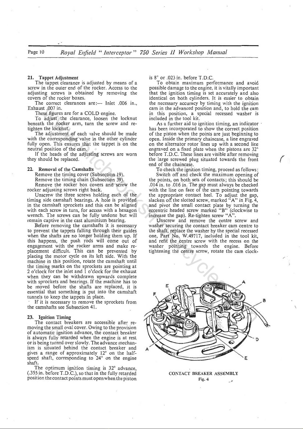
To
adjust
the
gap,
slacken off the slotted screw,
marked
"A"
in Fig.
4,
and
pivot
the small
contact
plate
by
turning
the
eccentric headed screw marked
"B
" (clockwise to
increase the gap). Re-tighten screw
"A"
.
Unscrew
and
remove the centre screw and
washer
securing the
contact
breaker
cam centre to
the
shaft
, replace the washer by
the
special recessed
one,
Part
No
. W.49717, included
in
the
tool
kit,
and
refit the centre screw with
the
recess
on
the
washer pointing towards the engine. Before
tightening the centre screw,
rotate
the
cam
clock-
COi\TACT
BREAKER
ASSEMBLY
Fig. 4
r
\


 Supplementary service manual")