HRESYS TL-LFP Series User manual

Content
Part 1 –Safety & Warning...................................................................................................................1
Part 2 –Product Introduction............................................................................................................. 2
2.1 –Overview.............................................................................................................................2
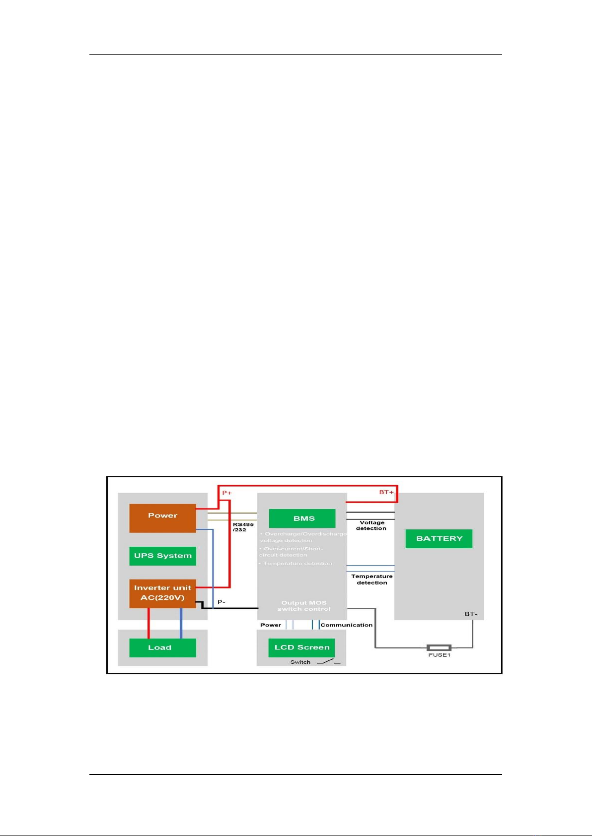
2.2 –Working Principle............................................................................................................... 2
2.3–Applications.........................................................................................................................2
2.5–Battery Model Name...........................................................................................................3
Part 4 –Operation & Maintenance.....................................................................................................3
4.1 –Requirements for Operation Environment........................................................................ 3
4.2 –Parameter Settings of Power Plant.................................................................................... 3
4.3 –Charge/Discharge Modes and Conditions......................................................................... 4
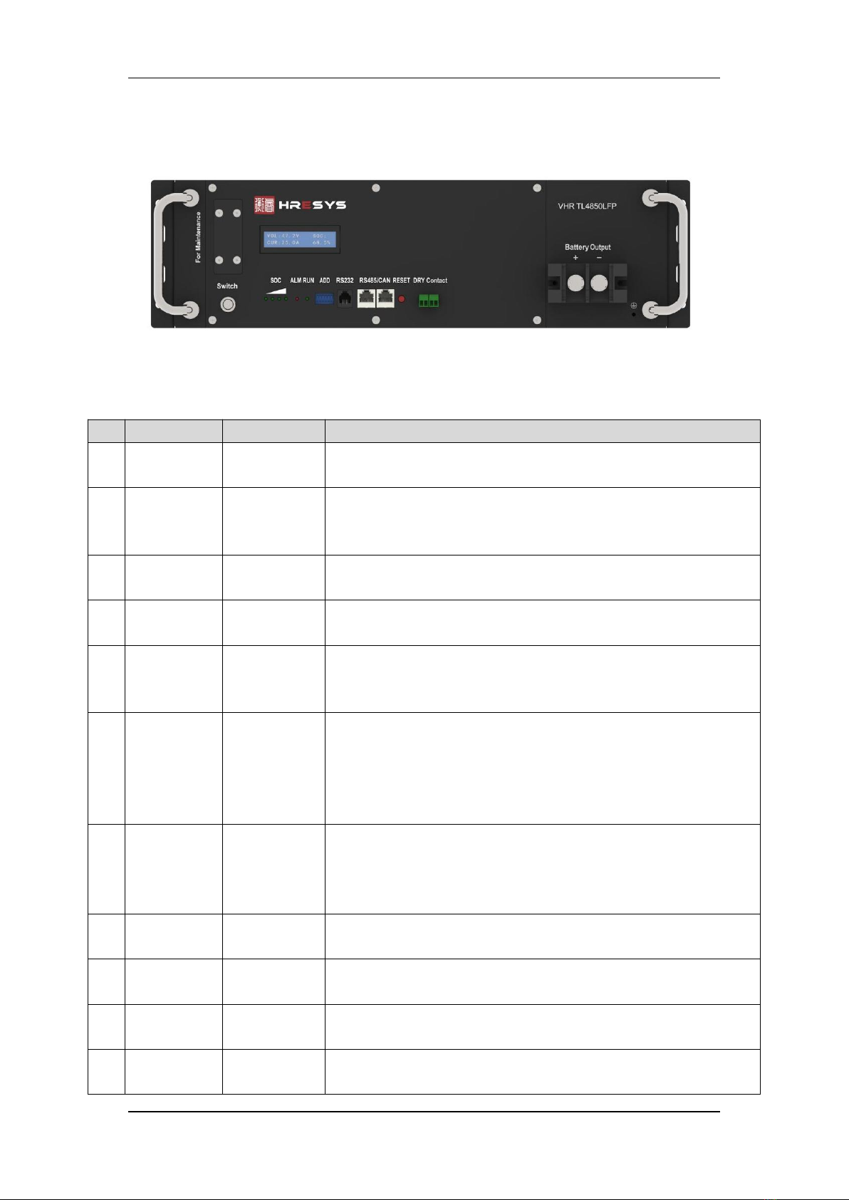
4.4 –Layout of Front Panel......................................................................................................... 5
4.5 - Shipment............................................................................................................................. 6
4.6 – Installation..........................................................................................................................6
Unboxing & Inspection........................................................................................................6
Preparation for Installation.................................................................................................6
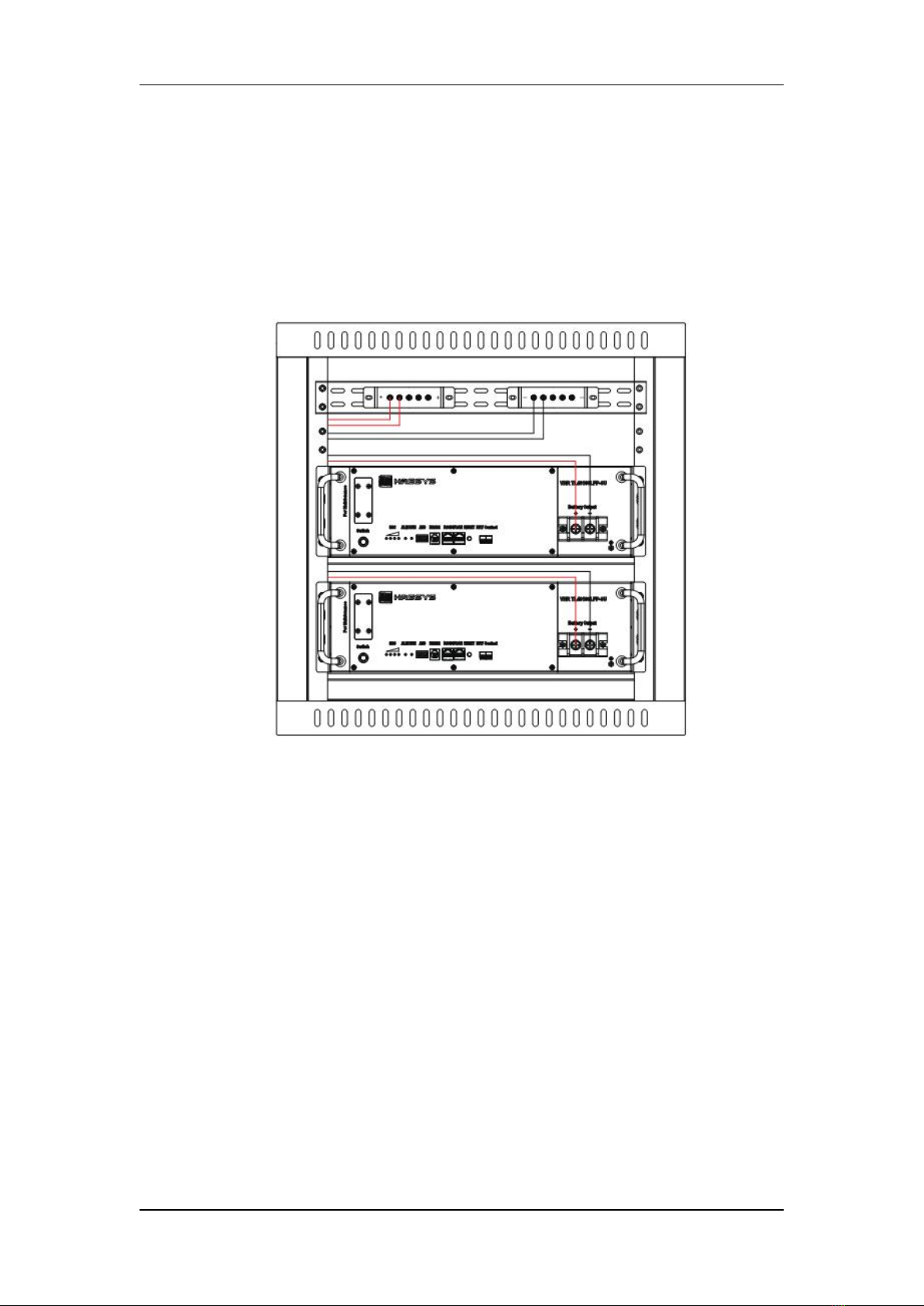
Installation of Battery Modules.......................................................................................... 7
4.7 – Storage................................................................................................................................9
4.7.1 Storage Requirements................................................................................................9
4.7.2 Judgement Conditions for Overdue Storage............................................................. 9
4.7.3 Recharge process..................................................................................................... 10
4.8 – Maintenance..................................................................................................................... 10
Part 5 –Troubleshooting & Solutions............................................................................................... 11
Annex 1 –Instructions for LED Flicker...............................................................................................12
Annex 2 –Instructions for ADD Dialing.............................................................................................13
Annex 3 –Communication Protocol for RS232 and RS485.............................................................. 14

TL-LFP Series LiFePO4Battery Operation Manual
1
Part 1 –Safety & Warning
The TL-LFP series LiFePO4battery system installation, operation, maintenance should follow
important recommendations in this manual:
The equipment shall be installed by the professional training staff
Battery maintenance should be carried out by the experienced professionals and aware
of the preventive measures on the potential harm of the battery.
Note: Be care of the risk of electric shock for large current in case of battery short
circuit, pay attention to the following points during operation
Remove watches, rings or other metal objects
Use tools with insulated handles
Do not place tools or metal objects on the battery
Do not direct access to the battery system to the mains grid power outlet
Do not put the battery system into fire, do not use or storage the battery near to the
high temperature source
Do not use liquid or other objects placed into the battery system.
Do not open or cut the battery, not to hit, throw or step on the battery
Using special communication between battery module and power plant to charge
battery
Be sure to subject to charge and discharge parameters setting in this manual
The output interface of the system is still voltage when grid power cut, avoid electric
shock or short circuit when operation
Please check if the box is damaged. If damaged, please immediately notify the supplier
If you find leaking liquid or white powder residue on product, prohibit operation.

TL-LFP Series liFePO4Battery Operation Manual
2
Part 2 –Product Introduction
2.1 – Overview
TL-LFP series lithium ion battery is a series of battery pack with advanced LiFePO4 technology
and intelligent integrated BMS, which has the advantages of long cycle life, light weight, small size,
safety and environmental protection.TL-LFP series lithium ion batteries can be used in a variety of
indoor and outdoor applications.
2.2 – Working Principle
The communication standby power supply consists of several lithium iron phosphate battery
units in series with the dedicated high performance and high reliability battery management
system (BMS).The +/- output terminal of the battery is connected to the +/- terminal of the
rectifier.When the mains supply is normal, the telecommunication equipment is supplied by
mains rectified power, and the battery pack is charged by rectified power.When the mains power
is interrupted, the backup power supply will be supplied to the telecommunication equipment
without delay to ensure that the power supply of the telecommunication equipment is not
interrupted until the mains power supply is restored or BMS automatically starts to protect the
power failure due to overdischarge protection.
Fig. 2.1 –Working Principal Diagram
2.3– Applications
Telecommunication
Terminal of FTTX

TL-LFP Series liFePO4Battery Operation Manual
3
Access network system
Indoor distribution system
Integrated outdoor power cabinet
Internet data center (IDC)
Energy storage system
2.5– Battery Model Name
Part 4 –Operation & Maintenance
4.1 – Requirements for Operation Environment
Table 4.1 –Requirements for Operation Environment
Temperature
Range (℃)
Discharge
-20 ~ +60
Charge
0 ~ +60
Storage
0~ 40
Recommended
Temperature (℃)
Discharge
+15 ~ + 35
Charge
+15 ~ + 35
Storage
+15 ~ + 30
Humidity
5% ~ 95%
4.2 – Parameter Settings of Power Plant
Lead-acid batteries can be replaced by lithium battery of TL-LFP series if power is matched.
Table 4.2 Parameter settings of power plant for lithium-ion battery.
Table 4.2 –Parameter Settings of Power Plant for TL48V-LFP Series Batteries
No.
Parameters
Units
Defaults
VHR TL48xxxLFP
LiFePO4battery
Rated capacity in Ah
Rated voltage(48V)
TL-LFP series
HRESYS brand

TL-LFP Series liFePO4Battery Operation Manual
4
1
Float voltage charge
V
54
2
Equal voltage charge
V
NA or 54
3
Standard charge current
A
0.2C
4
Charge current limitation
A
0.5C ~ 1.0C
5
LVLD (Low voltage load disconnection)
V
>44
6
LVBD (Low voltage battery disconnection)
V
>41
7
Temperature compensation for float charge
-mV/℃
NA
8
Temperature compensation for equalization
charge
-mV/℃
NA
NOTE: 1.Equalization charge is requested to switch off for TL-LFP series battery.
2.Rectifier parameter shall be set according to specific site requirement based on battery units used.
3.system instantaneous discharge and charge current shall be less than 250A for each module.
4.3 – Charge/Discharge Modes and Conditions
Table 4.3 Charge Modes and Conditions
Table 4.4 Discharge Modes and Conditions
Cell Temperature
Recommended Charge
Fast Continuous Charge
<0℃
No Charge Allowed
No Charge Allowed
0℃~ 10℃
Charge Current: 0.1C
Charge Current: 0.2C
10℃~20℃
Charge Current: 0.2C
Charge Current: 0.5C
20℃~30℃
Charge Current: 0.3C
Charge Current: 1.0C
30℃~40℃
Charge Current: 0.3C
Charge Current: 1.0C
40℃~60℃
Charge Current: 0.3C
Charge Current:0.5C
>60℃
No Charge Allowed
Cell Temperature
Recommended Discharge
Fast Discharge
<-20℃
No Discharge Allowed
-20℃~0℃
Discharge Current: 0.2C
Discharge Current: 0.5C
0℃~20℃
Discharge Current: 0.5C
Discharge Current: 1.0C
20℃~50℃
Discharge Current: 0.5C
Discharge Current: 1.0C
50~60℃
Discharge Current: 0.2C
Discharge Current: 0.5C
>60℃
No Disharge Allowed

TL-LFP Series liFePO4Battery Operation Manual
5
4.4 – Layout of Front Panel
Fig. 4.1 –Layout of Front Panel for TL-LFP Series Batteries
Table 4.5 –Instruction for Layout of Front Panel
No.
Marks
Functions
Detailed Information
1
Power
Switch
ON/OFF switch
When turn-off, battery get into sleep mode, and cut-off output, the alarm
output also will be stopped.
2
SOC
Indicators for
capacity
There are four green LED lights in front panel indicating SOC.SOC is short for
state of charge. Each SOC LED light represents 25% of rated capacity. Detailed
information is shown in Annexed Table 1.1.
3
ALM
Indicator for
alarms
There is one red LED light in front panel indicating alarms. Detailed information
is shown in Annexed Table 1.2.
4
RUN
Indicator for
running status
There is one green LED light in front panel indicating running status. Detailed
information is shown in Annexed Table 1.2.
5
ADD
Address of
communication
ADD is applicable to modules connected in parallel. ADD consists of four binary
bits, and maximum quantity of batteries connected in parallel is 64pcs (2^6).
Detailed information is shown in Annex 2.
6
RS232
Up-link
communication
port
It is adopting RS-232 series port to upload data. Contents of data transmit
include BMS parameters, battery running status, alarms, etc.Generally, speed
rate of RS-232 is 1200bps. RS232 up-link communication can be available for the
battery module with a binary communication address of 0000 (Master PACK).
Protocol for RS232 communication is shown in Annexed Table 3.1
7
RS485
Cascading
communication
port
It is adopting RS485 series port communication pattern to upload data.
Communication of modules connected in parallel (Slave PACKs) is available
through RS 485. Data of slave PACKs will be transmitted to Master PACK.
Protocol for RS232 communication is shown in Annexed Table 3.2
8
RESET
Reset button
Press RESET button when abnormity occurs to assure stability of battery
performance.
9
DRY CONTACT
(Optional)
The signal
interface
It is usually triggered by alarm or protection
10
Battery Output
Terminals for
battery output
Using terminals with two or four cores. Polarities are +, -, +, - from left to right.
The two ‘+’and ‘-’are equal relatively.
11
For
Maintenance
For
maintenance
N.A.

TL-LFP Series liFePO4Battery Operation Manual
6
12
LCD(Optional)
LCD display
Displays current system total voltage, current and battery status
13
GND
Protective
ground
M4 screw
4.5 - Shipment
The battery should be packed in cartons under the condition of half capacity 20%-50% for
shipment. The violent vibration, impaction or squeezing should be avoided in the transport
process; neither is exposed in the sunlight nor rain. The batteries shall be shipped by normal
transportation such as by road, by train, by ocean or by air.
4.6 – Installation
Unboxing & Inspection
Please read this manual before installation.
Please inspect the package before unboxing, if any destroy with appearance, contact
with the supplier as soon as possible.
This device shall be installed and operated by professionals.
Preparation for Installation
Batteries shall not be placed in direct sunshine or close to heat source.
Batteries shall be installed in place with good ventilation to assure enough heat
dissipation.
Batteries shall be placed in are with clean ambient and low humidity.
Heavy weight shall not be placed on any cable.
Required tools and materials are available. Use insulated tools. The following figure is
for reference only.
Item
Tool Item
Remark for use
1
Insulation gloves
Insulation protection for body
2
Insulation taps
Insulation protection for tools
3
Screw drivers
Fix the cables of the batteries & power plant
4
Multi meter
Measure the module voltage in commission
5
Current meter
Measure the module current in commission
6
USB to rs485 cable
For communication between the batteries and laptop
7
Laptop
Operate the software

TL-LFP Series liFePO4Battery Operation Manual
7
Installation of Battery Modules
1) Installation and fixation
Battery modules of TL-LFP series are applicable to installation in 19-inch cabinets and
wall-hanging.
19inch cabinet installation
Insert battery module into 19 inch cabinet, and fix two handles of battery module with
cabinet rack using 4pcs M6 screws.
Wall-hanging installation
Wall-hanging installation also can be adopted, fix two handles of battery module with
triangle rack on the wall using 4pcs M6 screws.
2) Ground connection
GND screw in front panel of battery is connected with ground through a flexible cable
no less than 6AWG.
3) Battery output connection
Before connect battery power cable, open the circuit breaker of the rectifier which
controls the battery circuit and make sure the circuit is disconnected.
Connect ‘+’of Battery Output with positive copper bus bar of power plant, and ‘-’with
negative copper bus bar.
If multi battery modules will be connected in parallel, connect ‘+’of Battery Output of
each battery module with positive copper bus bar of power plant, and ‘-’with negative

TL-LFP Series liFePO4Battery Operation Manual
8
copper bus bar separately.
Length of cable between battery module and power plant shall be less than 2.0m. To
make sure similar voltage drop of cable for each battery, length of all positive and
negative cables should be the same.
Color for cable between ‘+’and positive female bar is suggested as red, and cable
between ‘-’and negative breaker or fuse as black.
4) Power on for battery module
When installation is accomplished, firstly turn on the battery switch and the LED
indicator will light up, then close the circuit breaker of the rectifier to power on. Once
power on for power plant, battery module will go into normal running status, and
discharge/charge can be available.
Parameter settings for lithium battery modules in power plant are shown in Table 4.2.
5) RS232/RS485 connection
If there is only one battery module in operation, communication between battery
module and upper computer can available through both RS232 and RS485.
If there are more than one battery modules in operation, parallel communication can
be available using RS485.
Communication protocols for RS232 and RS485 are shown in Annex 3.
6) Discharge with dummy load
Dummy load cannot be larger maximum discharge current of each battery model in

TL-LFP Series liFePO4Battery Operation Manual
9
Table 2.1, and LVBD is larger than 41.0V.
Voltage drop on cable between battery module and power plant shall be less than 0.5V.
4.7 – Storage
4.7.1 Storage Requirements
1. Place modules according to the signs on the packing case during storage. Do not put modules
upside down or sidelong.
2. Stack modules packing cases by complying with the stacking requirements on the external
package.
3. The storage environment requirements are as follows:
− Ambient temperature: 0–40°C; recommended storage temperature: 20–30°C
− Relative humidity: ≤95%
− In a dry clean place with proper ventilation
− In a place that is away from corrosive and organic substances (including gas)
− In a place free from direct sunlight
− At least 2 meters away from heat sources (such as a heater)
4. The warehouse keeper should collect TL-LFP modules storage information every month and
periodically report the modules inventory information to the planning department. The modules
that have been stored overdue should be recharged in a timely manner.
5. The modules should be delivered based on the "first in, first out" rule.
6. Install modules in a dry, clean, and ventilated environment that is free from sources of strong
infrared radiation, organic solvents, and corrosive gases. Do not expose the modules to sunlight
or water and keep them far away from sources of ignition.
4.7.2 Judgement Conditions for Overdue Storage
The battery storage shall be in the clean and dry ventilation room at the temperature of 0~40°C.
It is recommended that the modules should not be stored for a long period.
Actual Storage
Temperature
Recharge Interval
Acceptance Criteria
0℃≤T≤30℃
12 month
Not reaching the time for recharge: Use the module
as soon as possible.
Reaching the time for recharge: Recharge the
module.
30℃≤T≤40℃
8 month
Note:
1. storage battery over 45°C or under 0°C will reduce battery life.
2.The storage duration (t) starts from the latest charge time on the module. The latest charge
time is updated after every charge.
3.If an module is qualified after charge, mark the latest charge time and the next recharge time
on the module packing case. The next recharge time is 8 months (stored above 30°C) or 12
months (stored below 30°C) later than the latest charge time. The total storage duration should

TL-LFP Series liFePO4Battery Operation Manual
10
not exceed the warranty period.
4.Directly handle bulging modules, no matter how long they are stored.
5.Battery performance degradation after long-term storage, please shorten shelf time as possible
as you can.
4.7.3 Recharge process
Recharge the module using a power system:Connect the positive and negative terminals of the
module to the output positive and negative terminals on the DC regulated power supply,
respectively.
Recharge parameter setting
Recharge parameter
Recharge Interval
Charge voltage
54.0V
Charge current
Using the default charge current limit; typically ≤0.2C
Termination condition
The charge duration is greater than 10 minutes and the charge
current is less than 0.03C, or the BMS is protected.
Note:Do not perform operations with power on when connecting the recharge cables.
4.8 – Maintenance
Please clean the dust by the dust collector when dust is accumulated on vent
Please use clean and dry cloth/fabric to clean up the cabinet, if need further cleaning, please
use neutral cleanser. Alcohol or ammonia synthesis is forbidden.
Carrying shall be handled gently, prevent from severe compact
Prevent battery from splashing liquid
Suggest inspect the tighten of output screw every two years

TL-LFP Series LiFePO4Battery Operation Manual
Part 5 –Troubleshooting & Solutions
Table 5.1 –Troubleshooting and Solutions
Troubles
Troubleshooting
Solutions
Battery cannot
discharge
Protection against under-voltage
Charge battery
Protection against over-temperature or
under-temperature (Ambient temperature is
lower than -20℃or higher than 60℃)
Regulate ambient temperature in the
range of -20℃to 60℃for discharge
Battery output is short circuit
Relieve short circuit and charge battery
Protection against over-current
Remove some unimportant load and
charge battery
System failure
Shutdown system and call maintenance
service
Battery cannot
charge
Battery is fully charged. Normal charge
management
Do not need to solve, will recovery
automatically
The positive and negative power cable inversely
connected to the terminal of the battery
Check the cable connection
Protection against over-temperature or
under-temperature (Ambient temperature is
lower than 0℃or higher than 60℃)
Regulate ambient temperature in the
range of 0℃to 60℃for charge
System failure
Shutdown system and call maintenance
service
Fail to start
The total battery voltage is too low, so the BMS
cannot start.
Contact the supplier to recovery the
battery voltage
The switch damaged, unable to start.
Contact the supplier to replace the
switch
LED damaged, battery on.
Observe whether the battery can
operate normal or not, contact the
supplier to replace the LED
The battery is disconnected internally
Shutdown system
Call for maintenance service
BMS power supply circuit damaged
Shutdown system
Call for maintenance service
All LED indicators
on
System failure
Shutdown system
Call for maintenance service
Communication
failure
Fault of communication cable
Inspect communication cable,check the
cable definition
System failure
Shutdown system
Call for maintenance service
Plug the wrong communication port
Check the communication port
Alarm light flash
during charging or
Cell temperature abnormal
check the environment temperature, if
only one cell temperature abnormal,

TL-LFP Series LiFePO4Battery Operation Manual
discharging
maybe connection is abnormal.call
maintenance service for help.
If all temperature nearly the same,
check the environment temperature.
Low SOC alarm
Do not need to solve
Cell or system low voltage alarm
Do not need to solve
Environment temperature abnormal
Do not need to solve
Battery display
capacity different
from actual
capacity
SOC display deviation
Calibrate the SOC by fully charge and
discharge battery
Different flash status of LED indicators represents corresponding running status or alarms.
Detailed information is shown Annex 1.
Annex 1 –Instructions for LED Flicker
Annex Table 1.1 –SOC LED Indicators Description
●
●
●
●
SOC
☼
☼
☼
☼
75%~100%
☼
☼
☼
○
50%~75%
☼
☼
○
○
25%~50%
☼
○
○
○
0%~25%
Note: ☼mean light on, ○mean light off
Table 1.2 LED instructions:
Pack Status
Protect
/Alarm
/Normal
RUN
ALM
SOC LED
Description
●
●
●
●
●
●
Power down/Sleep
——
OFF
OFF
OFF
OFF
OFF
OFF
——
Standby
Normal
Flash 1
OFF
According to the SOC
Standby
Alarm
Flash 1
OFF
——
Charge
Normal
Flash 3
OFF
According to the SOC
——
temperature
Alarm
Flash 3
Flash
2
——
Overcharge
voltage
protection
Flash 1
OFF
Over
temperature,
Flash 1
Flash
2

TL-LFP Series LiFePO4Battery Operation Manual
under-temper
ature,
over-current
protection
Discharge
Normal
Normally
on
OFF
According to the SOC
——
Temp Alarm
Normally
on
Flash
2
——
Under voltage
protection
Flash 1
OFF
Over
temperature,
under-temper
ature,
over-current
protection
Flash 1
Flash
2
Charge / Discharge /
Standby
The fault
OFF
Norm
ally
ON
OFF
LED Flash State
Light
Extinguish
Flash1
0.25S
3.75S
Flash2
0.5S
0.5S
Flash3
0.5S
1.5S
Annex 2 –Instructions for ADD Dialing
ADD is applicable to modules connected in parallel. ADD consists of four binary bits, and
maximum quantity of batteries connected in parallel is 64pcs (2^6). BMS only identify ADD
dialing one time after reset, so reset BMS as change ADD dialing.
Annexed Table 2.1 –Instruction for Addresses of Communication
Instructions for ADD Dialing
Module No.
Binary Code
Remarks
1
2
3
4
5
6
OFF
OFF
OFF
OFF
OFF
OFF
PACK 1
000000
Master PACK, supports
RS232
ON
OFF
OFF
OFF
OFF
OFF
PACK 2
000001
Slave PACK
OFF
ON
OFF
OFF
OFF
OFF
PACK 3
000010
Slave PACK
ON
ON
OFF
OFF
OFF
OFF
PACK 4
000011
Slave PACK

TL-LFP Series LiFePO4Battery Operation Manual
OFF
OFF
ON
OFF
OFF
OFF
PACK 5
000100
Slave PACK
ON
OFF
ON
OFF
OFF
OFF
PACK 6
000101
Slave PACK
OFF
ON
ON
OFF
OFF
OFF
PACK 7
000110
Slave PACK
ON
ON
ON
OFF
OFF
OFF
PACK 8
000111
Slave PACK
OFF
OFF
OFF
ON
OFF
OFF
PACK 9
001000
Slave PACK
ON
OFF
OFF
ON
OFF
OFF
PACK 10
001001
Slave PACK
OFF
ON
OFF
ON
OFF
OFF
PACK 11
001010
Slave PACK
ON
ON
OFF
ON
OFF
OFF
PACK 12
001011
Slave PACK
OFF
OFF
ON
ON
OFF
OFF
PACK 13
001100
Slave PACK
ON
OFF
ON
ON
OFF
OFF
PACK 14
001101
Slave PACK
OFF
ON
ON
ON
OFF
OFF
PACK 15
001110
Slave PACK
ON
ON
ON
ON
OFF
OFF
PACK 16
001111
Slave PACK
OFF
OFF
OFF
OFF
ON
OFF
PACK 17
010000
Slave PACK
ON
OFF
OFF
OFF
ON
OFF
PACK 18
010001
Slave PACK
OFF
ON
OFF
OFF
ON
OFF
PACK 19
010010
Slave PACK
ON
ON
OFF
OFF
ON
OFF
PACK 20
010011
Slave PACK
OFF
ON
OFF
OFF
ON
OFF
PACK 21
010100
Slave PACK
ON
OFF
ON
OFF
ON
OFF
PACK 22
010101
Slave PACK
OFF
ON
ON
OFF
ON
OFF
PACK 23
010110
Slave PACK
ON
ON
ON
OFF
ON
OFF
PACK 24
010111
Slave PACK
OFF
OFF
OFF
ON
ON
OFF
PACK 25
011000
Slave PACK
ON
OFF
OFF
ON
ON
OFF
PACK 26
011001
Slave PACK
OFF
ON
OFF
ON
ON
OFF
PACK 27
011010
Slave PACK
ON
ON
OFF
ON
ON
OFF
PACK 28
011011
Slave PACK
OFF
OFF
ON
ON
ON
OFF
PACK 29
011100
Slave PACK
ON
OFF
ON
ON
ON
OFF
PACK 30
011101
Slave PACK
OFF
ON
ON
ON
ON
OFF
PACK 31
011110
Slave PACK
ON
ON
ON
ON
ON
OFF
PACK 32
011111
Slave PACK
Annex 3 –Communication Protocol for RS232 and RS485
There is one RS232 port in front panel for up-link communication between batter module and
upper computer, and one or two RS485 port in front panel for cascade communication for
battery modules connected in parallel.
1) RS-232
The system uses/through 6Pin straight PCB welding socket(RJ11) to provide RS-232 protocol, the pin
assignment of RJ11 is defined as follows
Table 1 RJ11 Pin Assignment

TL-LFP Series LiFePO4Battery Operation Manual
2) RS-485
The system uses/through 8Pin straight PCB welding socket(RJ45) to provide RS-485 protocol, the pin
assignment of RJ45 is defined as follows。
Table 2 RJ45 Interface definition
RJ11 Pin
Definition Description
1
GND
2
SWCLK
3
Pack transmit; Computer receiver
4
BMS receiver; Computer transmit
5
RS232_GND
6
SWDIO
RJ45 Pin
Definition description
TL4850/48100
TL48150
1
RS485_B
RS485_B
2
RS485_A
RS485_A
3
RS485_B
GND
4
CAN_L
CAN_L
5
485_B
485_B
6
485_A
485_A
7
GND
GND
8
CAN_H
CAN_H
Table of contents
Other HRESYS Camera Accessories manuals