—8 —
SPK-DVF5
2-2. ELECTRICAL PARTS LIST
Ref. No. Part No. Description Ref. No. Part No. Description
NOTE:
•Due to standardization, replacements in the
parts list may be different from the parts
specifiedinthe diagrams orthecomponents
used on the set.
•-XX, -X mean standardized parts, so they
may have some difference from the original
one.
•Items marked “*”are not stocked since they
are seldom required for routine service.
Some delay should be anticipated when
ordering these items.
•CAPACITORS:
uF: µF
•RESISTORS
All resistors are in ohms.
METAL: metal-film resistor
METAL OXIDE: Metal Oxide-film resistor
F: nonflammable
•COILS
uH: µH
•SEMICONDUCTORS
In each case, u: µ, for example:
uA...: µA... , uPA... , µPA... ,
uPB... , µPB... , uPC... , µPC... ,
uPD..., µPD...
When indicating parts by reference number,
please include the board name.
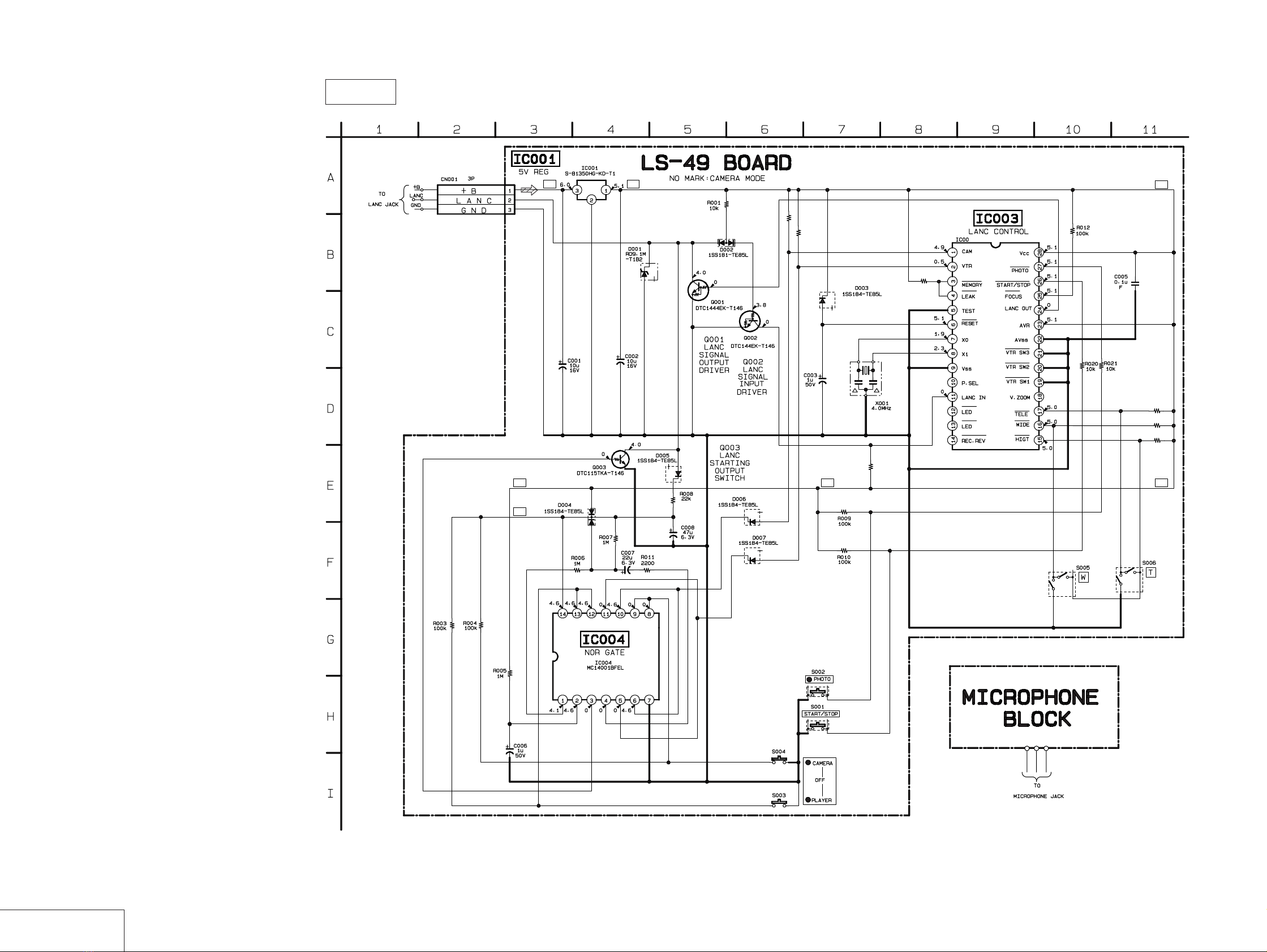
A-7073-569-A LS-49 BOARD, COMPLETE
*********************
< CAPACITOR >
C001 1-124-779-00 ELECT CHIP 10uF 20% 16V
C002 1-124-779-00 ELECT CHIP 10uF 20% 16V
C003 1-126-193-11 ELECT 1uF 20% 50V
C005 1-163-038-91 CERAMIC CHIP 0.1uF 25V
C006 1-126-193-11 ELECT 1uF 20% 50V
C007 1-124-778-00 ELECT CHIP 22uF 20% 6.3V
C008 1-126-205-11 ELECT CHIP 47uF 20% 6.3V
< CONNECTOR >
*CN001 1-564-705-11 PIN, CONNECTOR (SMALL TYPE) 3P
< DIODE >
D001 8-719-106-47 DIODE RD9.1M-T1B2
D002 8-719-820-05 DIODE 1SS181-TE85L
D003 8-719-801-78 DIODE 1SS184-TE85L
D004 8-719-801-78 DIODE 1SS184-TE85L
D005 8-719-801-78 DIODE 1SS184-TE85L
D006 8-719-801-78 DIODE 1SS184-TE85L
D007 8-719-801-78 DIODE 1SS184-TE85L
< IC >
IC001 8-759-512-69 IC S-81350HG-KD-T1
< TRANSISTOR >
Q001 1-801-806-11 TRANSISTOR DTC144EK-T146
Q002 1-801-806-11 TRANSISTOR DTC144EK-T146
Q003 8-729-027-48 TRANSISTOR DTC115TKA-T146
< RESISTOR >
R001 1-216-073-91 RES-CHIP 10K 5% 1/10W
R003 1-216-097-11 RES-CHIP 100K 5% 1/10W
R004 1-216-097-11 RES-CHIP 100K 5% 1/10W
R005 1-216-121-11 RES-CHIP 1M 5% 1/10W
R006 1-216-121-11 RES-CHIP 1M 5% 1/10W
R007 1-216-121-11 RES-CHIP 1M 5% 1/10W
R008 1-216-081-00 METAL CHIP 22K 5% 1/10W
R009 1-216-097-11 RES-CHIP 100K 5% 1/10W
R010 1-216-097-11 RES-CHIP 100K 5% 1/10W
R011 1-216-057-00 METAL CHIP 2.2K 5% 1/10W
R012 1-216-097-11 RES-CHIP 100K 5% 1/10W
R013 1-216-097-11 RES-CHIP 100K 5% 1/10W
R014 1-216-073-91 RES-CHIP 10K 5% 1/10W
R015 1-216-097-11 RES-CHIP 100K 5% 1/10W
R016 1-216-097-11 RES-CHIP 100K 5% 1/10W
R017 1-216-097-11 RES-CHIP 100K 5% 1/10W
R018 1-216-097-11 RES-CHIP 100K 5% 1/10W
R019 1-216-097-11 RES-CHIP 100K 5% 1/10W
R020 1-216-073-91 RES-CHIP 10K 5% 1/10W
R021 1-216-073-91 RES-CHIP 10K 5% 1/10W
< SWITCH >
S001 1-572-683-21 SWITCH, KEY BOARD (START/STOP)
S002 1-692-838-21 SWITCH, TACTILE (RUBBER) (PHOTO)
S003 1-572-688-11 SWITCH, PUSH (1 KEY) (PLAYER)
S004 1-572-288-21 SWITCH, PUSH (CAMERA)
S005 1-692-247-11 SWITCH, TACTIL (2 CLICK) (W)
S006 1-692-247-11 SWITCH, TACTIL (2 CLICK) (T)
< VIBRATOR >
X001 1-579-902-11 VIBRATOR, CERAMIC 4MHz
**************************************************************
ACCESSORIES
***********
2-391-512-00 RING (5), RETAINING, E TYPE
3-050-146-01 BASE (A)
3-055-228-01 CUSHION (A) (SMALL), BASE
3-061-058-01 RING (B) (M37), PREVENTION
3-061-059-01 RING (B) (M30), PREVENTION
3-071-370-01 GREASE (BLUE)
3-076-926-01 BASE (C)
3-082-301-11 MANUAL, INSTRUCTION
(ENGLISH/FRENCH/GERMAN/SPANISH)
3-082-301-21 MANUAL, INSTRUCTION
(PORTUGUESE/SWEDISH/ITALIAN/DUTCH)
3-082-301-31 MANUAL, INSTRUCTION
(RUSSIAN/ARABIC/CHINESE/KOREAN)
3-082-303-01 BASE (D)
3-941-465-01 BELT, STRAP
3-953-086-01 BRACKET
*3-970-217-01 SCREW, CAMERA FITTING
3-970-221-02 BASE, SLIDE
3-976-858-01 CUSHION (B), BASE
LS-49
—8 —
Sony EMCS Co. 2003B1600-1
©2003.2
Published by DI Customer Center
9-876-219-11