Rhotheta RT-400 User manual

User Manual
RT-400 DF Scout

RHOTHETA RT-400 DF Scout Draft
RHOTHETA Page 2 of 63 User Manual
Edited by:
RHOTHETA Elektronik GmbH
Kemmelpark
Dr.-Ingeborg-Haeckel-Str. 2
82418 Murnau
Germany
Tel.: +49 8841 4879 - 0
Fax: +49 8841 4879 - 15
Internet: www.rhotheta.de
E-Mail: email@rhotheta.de
Copyright © RHOTHETA Elektronik GmbH
All rights reserved
-Issue: 2020/08/14 [Rev 1.05]
-Document-ID: 12-9-1-0020-3-1-61
Note
The manufacturer reserves the right to make modifications at any time and without previous
information of the here described product.

RHOTHETA RT-400 DF Scout Draft
RHOTHETA Page 3 of 63 User Manual
Content
1Overview........................................................................................................................... 4
2Installation........................................................................................................................ 4
2.1 System Requirements ............................................................................................................................4
2.2 Installing the DF Scout Application.........................................................................................................5
2.2.1 Licensing....................................................................................................................................6
2.2.2 WiFi Connection.........................................................................................................................7
2.2.3 MAP Data...................................................................................................................................7
2.3 Compass calibration ...............................................................................................................................7
3Map Pages ........................................................................................................................ 9
3.1 Basic Elements of the Bottom Line.......................................................................................................10
3.2 Basic Elements and Functions of the Map Section ..............................................................................12
3.3 Map Page Bearing ................................................................................................................................14
3.4 Map Page Decode ................................................................................................................................16
3.5 Map Page Scan ....................................................................................................................................20
3.6 Special Map Operations .......................................................................................................................22
3.6.1 Creating a semi-automatic target position on the map ............................................................22
3.6.2 Creating a manual target position on the map.........................................................................25
3.6.3 Deleting an item on the map....................................................................................................26
4Dialog Pages .................................................................................................................. 27
4.1 Main Menu ............................................................................................................................................27
4.2 Input dialogues .....................................................................................................................................29
4.2.1 Numerical Input Dialog ............................................................................................................29
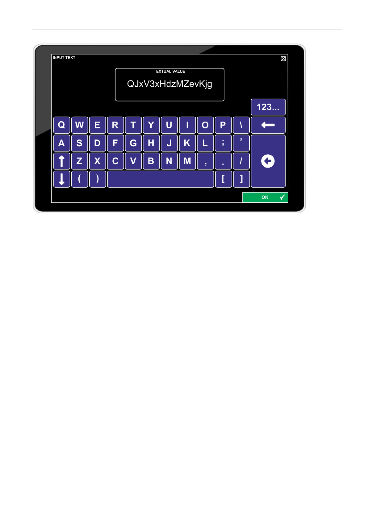
4.2.2 Textual Input Dialog .................................................................................................................30
4.2.3 Technical Input Field (Standard Version) ................................................................................32
4.2.4 Technical Input Field in Map Page Scan .................................................................................35
4.3 SAR Scan Settings ...............................................................................................................................37
4.3.1 Configuring Stop Condition......................................................................................................39
4.4 Display Settings ....................................................................................................................................40
4.5 System Settings....................................................................................................................................44
4.6 Service Settings....................................................................................................................................48
4.6.1 Export Configuration Dialog.....................................................................................................51
4.6.2 Import Configuration Dialog .....................................................................................................53
4.6.3 KML Logging and Export Log Files Dialogs ............................................................................54
4.7 Error and Warning messages...............................................................................................................58
5Troubleshooting ............................................................................................................ 61
6Notes............................................................................................................................... 63

RHOTHETA RT-400 DF Scout Draft
RHOTHETA Page 4 of 63 User Manual
1 Overview
This guide is part of the product RT-400 DF Scout and must be kept with the product
throughout its lifetime.
The RT-400 DF Scout is designed to control and operate a RHOTHETA direction finder
antenna unit through Wi-Fi connectivity.
It operates on tablet computers running ANDROID operating systems.
Operation, including access to geographical maps, is independent from internet
connections.
The RT-400 DF Scout application is a map-based tool, helping to quickly find your way to
the source of a transmission, for example, a search and rescue (SAR) beacon. The
application is built around a large map screen, offering three major operating modes or
map pages:
•Map Page Bearing for bearing transmission sources
•Map Page Scan for finding specific SAR transmissions
•Map Page Decode for decoding COSPAS-SARSAT transmissions of COSPAS-
SARSAT compatible SAR beacons
The user might use the RT-400 DF Scout either to simply follow a “line of bearing”, or to
collect several “lines of bearing”, defining a possible target position manually or semi-
automatically, or to decode a possible target position from a COSPAS-SARSAT
transmission.
2 Installation
2.1 System Requirements
Minimum Tablet Requirements
Operating System:
Android 5.1 or newer
Recommended: Android 9 (GMS) or newer
Processor: Qualcomm® Snapdragon 410 (MSM8916) (4 cores 1.2 GHz)
Memory: 2 GB RAM / 16 GB internal storage
Interfaces: Micro SD-Slot (128 GB)
Display:
Minimum: 7’’
Recommended: 8’’ – 10.5’’
Important Features:
- Wi-Fi Module
- Compass
- GNSS Receiver (e.g. GPS)

RHOTHETA RT-400 DF Scout Draft
RHOTHETA Page 5 of 63 User Manual
2.2 Installing the DF Scout Application
The .apk file shall be copied to the internal memory or to a SD card placed into the tablet.
Double-tap the .apk file.
In standard Android installations, the installation of apps obtained from unknown sources is
not enabled and must be unblocked manually. Tap on “settings” to open the relevant settings
dialog:
In the settings dialog, the “Lock screen and security” menu allows to enable the installation by
activating “Unknown sources”.
Confirm with “OK”, then confirm that the application shall be installed by tapping “INSTALL”.
Once the installation is successful, the application can be opened by tapping “OPEN”.
To be able to use map functions, access to the device’s location must be allowed, and file
access must also be allowed.
To allow automatic brightness settings by RT-400 DF Scout, the system’s permissions must
be modified. Confirm this with “OK”, then allow permission to change system settings by
tapping the slider symbol:

RHOTHETA RT-400 DF Scout Draft
RHOTHETA Page 6 of 63 User Manual
After that, use the “Back” button of your tablet to go back to the DF Scout application:
Next, the license code has to be entered.
Note: Depending on Android versions used and on manufacturer-specific adaptations, some
of the dialogs shown might look slightly different on your tablet computer.
2.2.1 Licensing
Each copy of RT-400 DF Scout must be licensed to the tablet on which it has been installed.
The licence is bound to the hardware used.
After sending the hardware ID to RHOTHETA, we will provide you with the required license
key. Tap “OK” to continue with entering the license code:
The license key can be entered through the textual input dialog and, if numbers are included,
through the numerical input dialogue.
If a part of the key has not been entered correctly, the procedure restarts, but with the same
key.
Note: The key code is case sensitive.

RHOTHETA RT-400 DF Scout Draft
RHOTHETA Page 7 of 63 User Manual
If successfully entered and confirmed with “OK”, the application will start.
2.2.2 WiFi Connection
The WiFi connection must be established before using the application.
Please check the settings of the particular tablet in order to activate the WiFi.
It is recommended to use the “auto reconnect” function of the tablet, so that the system
automatically reconnects to the wireless network after starting the tablet or loss of connection.
Note that only one WiFi hotspot should be set to “auto reconnect” when using this function.
If the antenna unit is activated, the corresponding SSID: RT-400 SN***** is available in the list
of accessible networks. To establish the connection to the antenna unit use the password:
rhotheta123.
2.2.3 MAP Data
Map Data used on Map Pages must be stored in an SD Card, with the map data being
located in the folder “OSM_tiles”.
Map data in the required data format is provided by RHOTHETA.
New additional map files must only be copied into the existing “OSM_tiles” folder to be
automatically found by the application.
While using the DF Scout application, map data from the SD Card is loaded into the internal
app storage to reduce access time. This causes the storage consumption of the application to
increase. It is possible to check the data in Android settings and to clear it if necessary.
2.3 Compass calibration
Before starting an operation, make sure the compass heading and orientation of the maps are
correct. If this is not the case, the compass inside the tablet must be calibrated.
There are several ways to do so. One of them is to use the “Google Maps” app, which is
preinstalled on an Android tablet. Alternatively, the calibration can be performed while working
with the DF Scout app. To get acquainted with the flow of motion needed for the calibration,
use Google Maps.

RHOTHETA RT-400 DF Scout Draft
RHOTHETA Page 8 of 63 User Manual
Start the “Google Maps” app and press the blue dot that identifies your own position. This
opens a menu in which you have to select the option “Calibrate compass”. Then follow the
instructions on the screen. If the calibration has been successful, a dialog with the message
“Compass calibrated” will show. Afterwards, switch back to the “DF Scout” app.

RHOTHETA RT-400 DF Scout Draft
RHOTHETA Page 9 of 63 User Manual
3 Map Pages
There are three main pages used during normal operation of the RT-400 DF Scout:
•Map Page Bearing
•Map Page Decode
•Map Page SAR Scan
They are selected through the Main Menu dialog page.
All those pages are divided into three main sections, as shown in the example (Map Page
Decode):
•Top line, showing the most important information regarding the beacon to be received,
with page-specific information. Refer to the specific map pages sub-chapters for more
details.
•Bottom line, showing all necessary information regarding the user’s position and DF
technical status.
•Map Section, showing the user’s position and GPS track, Lines of Bearing, and target
positions on a map.
There are several symbols on each page indicating system status information or allowing
basic system operation.

RHOTHETA RT-400 DF Scout Draft
RHOTHETA Page 10 of 63 User Manual
3.1 Basic Elements of the Bottom Line
Basic Elements of the Bottom Line
Symbol Description
The GPS symbol indicates whether GPS/GNSS data is
available or not. When GPS data is not available,
there should
be a gray symbol.
The COMPASS symbol indicates whether
compass data is
available (green) or not (gray).
DIRECTION FINDER indicates whether dat
a from the Antenna
Unit is available (green) or not (red).
LOGGING ON indicates whether logging is activated (green) or
not (gray).
BATTERY VOLTAGE ANTENNA UNIT indicates the battery
voltage of the Antenna Unit.
BATTERY STATUS TABLET indicates the battery status of the
tablet (full battery is indicated with battery symbol entirely green
colored and 100%).
Tap and hold the fields above for a few seconds to open the “Service Settings: KML Logging
Dialog” (Refer to Chapter “KML Logging and Export Log Files Dialogs” for details)
GPS POSITION indicates the current Position (Latitude /
Longitude)
of the DF as calculated from GNSS (GPS)
reception.
SPEED OVER GROUND indicates the current speed over
ground of the DF, as calculated from GNSS (GPS) reception.
COURSE OVER GROUND indicates the Course Over Ground
of the DF as calculated from GNSS (GPS) reception.
ALTITUDE indicates the Altitude of the DF as calculated from
GNSS (GPS) reception.
Tap and hold the fields above for a few seconds to open the Display Settings Dialog, where
the format of the indications can be changed.
HEADING indicates the Heading of the Tablet as calculated
from the internal compass.
Tap and hold the HEADING field for a few seconds to open the System Settings Dialog,
where the Heading Source may be changed.
DATE AND TIME shows current date and time received from
GPS, shown in US data format (Month/Day/Year).
Tapping the REPEAT BUTTON displays the last bearing with a
gray-colored Line Of Bearing.
Important: If there is an active bearing signal, tapping the
REPEAT BUTTON has no effect!
Furthermore, an incoming bearing will always have priority and
immediately terminate the repeat view.

RHOTHETA RT-400 DF Scout Draft
RHOTHETA Page 11 of 63 User Manual
Basic Elements of the Bottom Line
Symbol Description
If the SAVE BUTTON is tapped during an active bearing, the
currently received bearing is shown permanently on the screen
as DIRECTION OLD (dotted Line of bearing). This is also valid
for the SAR Scan. There is no need to save a COSPAS-
SARSAT position received, as this is done autom
atically in
decode mode (Map Page Decode).
Tapping the CLEAR BUTTON opens a dialog to delete the
currently selected item on the map.
It can be confirmed by
tapping “OK” or rejected by tapping
the ESCAPE cross within
the message.
If nothing is selected,
the CLEAR function clears the internal
bearing value averaging memory. The averaging memory
enhances bearing accuracy and delivers a useful bearing
display even with weak receiving
signals. The averaging
procedure causes a drag error, which might influenc
e the
bearing value, if changing heading too quickly. In this case, the
indicated bearing value will be lagging a bit to the actual
bearing value.
By tapping
the CLEAR BUTTON after a distinct change of
heading, the corrected bearing value will be displayed
immediately.
Tapping the MENU BUTTON opens the Menu settings dialog.

RHOTHETA RT-400 DF Scout Draft
RHOTHETA Page 12 of 63 User Manual
3.2 Basic Elements and Functions of the Map Section
Basic Elements and Functions of the Map Section
Symbol Description
Tapping the CENTER BUTTON centers the bearing rose (azimuth dial)
on the screen.
An ACTUAL Line Of Bearing indicates the direction from the actual
position of the Antenna Unit to the last bearing. The Bearing Indication
Hold Time defines how long this line will be visible on the screen if no
other bearing arrives (See “Display Settings Dialog”).
If a new bearing arrives, the old line will disappear.
If the REPEAT button is tapped after the signal falls
below the squelch
level, the last bearing will be repeated, and the line will be shown in gray
color.
If the SAVE button is tapped while an ACTUAL Line of Bearing
(including a repeated one) is being displayed, it will be stored as a
DIRECTION OLD Line of Bearing.
DIRECTION OLD Line of Bearing indicates Lines Of Bearings stored
from an ACTUAL Line of Bearing using the SAVE Button. Both the
user’s position and Line Of Bearing saved
at the time of reception are
shown.
Special functions and looks are available in scan mode (Map Page
Scan):
If a line of bearing is received during SCAN mode in a COSPAS-
SARSAT frequency, it is stored automatically.
D
epending on the receive frequency, stored DIRECTION OLD Line Of
Bearings receive different colors, and the frequency of reception is
written alongside the line.
If a DIRECTION OLD Line of Bearing is tapped, it will be highlighted and
shown as a black line with yellow background for some seconds.
If the Button CLEAR BUTTON is tapped in this state, the related dialog
for deleting will be opened.
Additional functions are available for Semi-
Automatic Target Positions
and described in the appropriate chapter.
The HEADING ARROW indicator is only used when the map view is
configured to “North Up” and shows the current TRUE heading which is
given by compass data and variation.
The user’s POSITION mark is in the center of the azimuth dial. Usually it
is indicated as a filled red circle.

RHOTHETA RT-400 DF Scout Draft
RHOTHETA Page 13 of 63 User Manual
Basic Elements and Functions of the Map Section
Symbol Description
The POSITION TARGET BEARING is an estimated target position,
based on semi-automatic calculation using Lines of Bearing or on the
user’s estimation (see Special Map Operations).
This symbol can be selected by tapping
it on the screen. A selected
symbol is highlighted with a black outline
and black text on yellow
background.
If the Button CLEAR BUTTON is tapped in this state, the related dialog
for deleting will be opened.
Otherwise, the highlight disappears after a few seconds and the symbol
keeps its original appearance.
Double-tap on an estimated beacon position on the map to create a
target position.
POSITION TARGET GPS is a target position based on GPS data from a
decoded COSPAS-SARSAT message
. The number inside the symbol
starts with “1” and is incremented with every new COSPAS-SARSAT
beacon ID. That means the first COSPAS-SARSAT message generates
a symbol with “1”. The number relates to the full beacon ID. The color is
automatically determined by the software. The actual position from the
last decoding is always shown with a circle around the symbol.
This symbol can be selected by tapping
it on the screen. A selected
symbol is highlighted with a black outline
and black text on yellow
background.
If the Button CLEAR BUTTON is tapped in this state, the related dialog
for deleting will be opened.
Otherwise, the marking disappears after a few
seconds and the symbol
keeps its original appearance.
A TRACK is the GPS track of the Antenna Unit.
It can be selected by tapp
ing it on the screen. A selected track is
highlighted and shown as a black line with yellow background.
If the Button CLEAR BUTTON is tapped in this state, the related dialog
for deleting will be opened.
Otherwise, the marking disappears after a few
seconds and the track
keeps its original appearance.

RHOTHETA RT-400 DF Scout Draft
RHOTHETA Page 14 of 63 User Manual
3.3 Map Page Bearing
On the map display, the user’s position is in the center of an azimuth dial (bearing rose),
whose upper edge points toward the direction of the heading.
The currently measured bearing is shown as a solid red line with a red dot as the current
position, while older bearing lines from other positions are shown as dotted lines. Refer to
“Basic elements of the Map Section” for a detailed explanation of symbols.
To provide a graphical distinction between marked positions, decoded positions (see chapter
“Map Page Decode”) are represented by a rectangle with an appropriate decode number,
which corresponds to a certain beacon ID. An estimated beacon position in bearing mode is
represented by a triangle with “T” inside (“Target”). Refer to chapter “Special Map Operations”
for details.
Basic Elements of the Top Line, Map Page Bearing
Symbol Description
The FREQUENCY field shows the current receiving frequency
while in bearing mode. Tap and hold
this area for a few
seconds to open the technical input field.
SAR SCAN is displayed instead of “FREQUENCY”, if Map
Page “Scan” is active.
The LEVEL indicator shows the receive signal strength of the
currently received signal as a
bar graph and numeric value.
The small figure below the bar graph is the currently set
squelch level.
Tap and hold the fields above for a few seconds to open the Technical Input Field.
(Standard Version)

RHOTHETA RT-400 DF Scout Draft
RHOTHETA Page 15 of 63 User Manual
Basic Elements of the Top Line, Map Page Bearing
Symbol Description
TRUE BEARING is the indication of the current / last true
bearing (bearing relative to north) and the elapsed time since
that bearing was last measured.
Tap and hold the field above for a few seconds to open the System Settings dialog.
ESTIMATED TARGET POSITION is the estimated
geographical position (Latitude / Longitude) of the target.
Estimated DISTANCE to the target.
Tap and hold the fields above for a few seconds to open the Display Settings dialog.

RHOTHETA RT-400 DF Scout Draft
RHOTHETA Page 16 of 63 User Manual
3.4 Map Page Decode
Map Page Decode allows to receive and decode COSPAS-SARSAT beacon data
transmissions, and to visualize their content. As long as a beacon is using a location protocol
and transmitting a valid position, the beacon is shown on the map. In the case that several
beacons are being received, they will be serially numbered, starting with 1.
Bearing mode is disabled while in Map Page Decode, and only frequencies between 406.022
MHz and 406.076 MHz may be selected.
Basic Elements of the Top Line, Map Page Decode
Symbol Description
The FREQUENCY field shows the current receiving frequency
while in decode mode. Tap and hold
this area for a few
seconds to open the technical input field.
The LEVEL indicator shows the receive signal strength of the
currently received signal as a
bar graph and numeric value.
The small figure below the bar graph is the currently set
squelch level.
Tap and hold the fields above for a few seconds to open the Technical Input Field (Standard
Version).
GPS DIRECTION (relative to North) towards the target,
calculated from the GPS position of the DF and the position
encoded in the COSPAS-SARSAT-message.
Note: Due to the limited accuracy, final approach should not be
based on GPS-DIR, but on bearing.

RHOTHETA RT-400 DF Scout Draft
RHOTHETA Page 17 of 63 User Manual
Basic Elements of the Top Line, Map Page Decode
Symbol Description
GPS DISTANCE towards the target, calculated from the GPS
positions of DF and target.
Note: Due to the limited accuracy, final approach should not be
based on GPS-Distance, but on bearing.
Distance unit is as
configured in the Display Settings Dialog.
15-HEX ID of the beacon. The 15 hexadecimal characters that
uniquely identify each 406 MHz beacon are called the beacon
identification or “Beacon 15 Hex ID”.
COUNTRY Code of the beacon.
This is the ITU Maritime Identification Digit (MID) country code.
Encoded BEACON POSITION (Latitude / Longitude) in the
format defined in the Display Settings Dialog.
Note: Availability and accuracy depends on the COSPAS-
SARSAT message format used. Many COSPAS-SARSAT
beacons do not use GNSS. Depending on the message data
format, the position resolution is between 4 arc minutes and 4
arc seconds.
MESSAGE DATE (in US format: Month/Day/Year) and time
when the transmission was received.
NEXT MESSAGE is the estimated remaining time until the next
message should be received. Usually, this should occur around
10 seconds before the counter is down to 0. If no signal is
received before 0 is reached, the
receiving location might be
disadvantageous. In that case, choosing a different location is
recommended.
Note: The beacon signal repetition rate is randomized from
47.5 to 52.5 seconds.
So, typically, the next transmission
occurs at a counter position between 7 and 12 seconds.
Tap and hold the field above for a few seconds to open the System Settings dialog.
DISPLAY MESSAGE shows the number of the currently
displayed Message (correlates with the number of the position
target on the map).
The arrow symbol opens the COSPAS-SARSAT DECODE
LIST.

RHOTHETA RT-400 DF Scout Draft
RHOTHETA Page 18 of 63 User Manual
It consists of a list of received COSPAS-SARSAT messages, of which one can be selected,
and the data decoded from the selected message.
Elements of the Top Line COSPAS-SARSAT Decode List
Symbol Description
The List of received COSPAS-SARSAT messages contains
all received and decoded COSPAS-SARSAT messages.
The list contains the serial number of the message, time and
date when the message has been received.
If the beacon is shown as a target on the map, “Map” is set to
“YES”, that means a target from encoded position data is
visualized on the map.
If the target has been removed from the map manually, or if no
position data has been decoded, this value will be set to “NO”.
A single list entry can be selected by tapping the corresponding
line. If it has been removed from the map before, by tapping
“SAVE” the corresponding target will be shown in the map
again, and Map will be set to “YES”.
To irrevocably delete the selected list
entry, hit CLEAR and
confirm with OK. A gap in the list will remain
, e.g. if beacon
number 3 is deleted in the example, beacons 2 and 4 will keep
those numbers.
A line of bearing on the map will always relate to the latest
received beacon.
BEACON IDENTIFICATION shows the 15-HEX ID of the
beacon. The 15 hexadecimal characters that uniquely identify
each 406 MHz beacon are called the beacon identification or
“Beacon 15 Hex ID”.

RHOTHETA RT-400 DF Scout Draft
RHOTHETA Page 19 of 63 User Manual
Elements of the Top Line COSPAS-SARSAT Decode List
Symbol Description
COUNTRY Code of the beacon.
This is the ITU Maritime Identification Digit (MID) country code.
The COMPLETE MESSAGE (short / long message) modulated
on the beacon signal is shown here in hexadecimal characters.
DECODE STATUS of the data message. “Sync. OK” means
the frame has been decoded without error. Only in this case,
the displayed data is reliable.
PROTOCOL TYPE shows the data protocol in which the
COSPAS-SARSAT message has been coded.
Elapsed time since the LAST PULSE of that beacon has been
received.
Encoded BEACON POSITION.
Note: Availability and accuracy depends on the COSPAS-
SARSAT message format used. Many COSPAS-SARSAT
beacons do not use GNSS. Depending on the message data
format, the position resolution is between 4 arc minutes and 4
arc seconds.
GPS DIRECTION (relative to North) towards the target,
calculated from the GPS position of the DF and the position
encoded in the COSPAS-SARSAT-message.
Note: Due to the limited accuracy, final approach should not be
based on GPS-DIR, but on bearing.
GPS DISTANCE towards the target, calculated from the GPS
positions of DF and target.
Note: Due to the limited accuracy, final approach should not be
based on GPS-Distance, but on bearing.
The RECEIVE FREQUENCY on which the selected message
has been received is shown here.
Here, the RECEIVE LEVEL is shown at which the selected
message has been received.
ESCAPE closes the COSPAS-SARSAT DECODE LIST and
switches back to Map Page Decode.

RHOTHETA RT-400 DF Scout Draft
RHOTHETA Page 20 of 63 User Manual
3.5 Map Page Scan
Scan Mode can be accessed through the MENU button on the Bottom Line.
SAR Scan is an excellent tool to detect and find a COSPAS-SARSAT beacon, which
transmits short but strong (5 W radiated power) data pulses on 406 MHz, but which also
transmits a continuous signal, or a high duty cycle signal, on 121.5 MHz (around 100 mW
radiated power or less).
A strong transmission has the advantage of a wide detection range of the beacon, while a
continuous signal allows far better bearing performance compared to pulses.
The RT-400 / DF Scout SCAN Algorithm combines both advantages in one function.
If the SAR Scan is activated, the system will wait for a COSPAS-SARSAT pulse on 406 MHz.
Compared to 121.5 MHz, the detection likelihood of a COSPAS-SARSAT pulse is higher due
to the strong transmitter power of approximately 5 W. Once the pulse has been detected, the
system calculates the direction to it. At the same time, the RT-400 systems “knows” that the
next COSPAS-SARSAT pulse will arrive after approximately 50 seconds, and uses this time
for scanning 121.5 MHz or 4 other adjustable frequencies. If the signal at 121.5 MHz has not
been detected, the RT-400 automatically switches back to 406 MHz. On the other hand, if a
121.5 MHz transmission has been detected, the user gets the possibility to stay on 121.5
MHz in order to operate with the continuous signal, which allows the operator to achieve a
better bearing performance and to find the target very fast.
The related map page only shows small visual differences compared to the Map Page
Bearing. On the map, bearings are shown together with the frequency on which the bearing
has been measured.
As with normal bearing mode, Lines of Bearing can be kept on the map by tapping “SAVE”,
with exception of those originating from 406 MHz (COSPAS-SARSAT) transmissions, which
Table of contents
Other Rhotheta Camera Accessories manuals