manuals.online logo
Brands
  1. Home
  2. •
  3. Brands
  4. •
  5. HSD
  6. •
  7. DC Drive
  8. •
  9. HSD 22-CT70 User manual

HSD 22-CT70 User manual

Popular DC Drive manuals by other brands

National Instruments NI MID-7604 user guide

National Instruments

National Instruments NI MID-7604 user guide

SOMFY Maestria WT Series instructions

SOMFY

SOMFY Maestria WT Series instructions

Danfoss VLT HVAC Design guide

Danfoss

Danfoss VLT HVAC Design guide

Trane TR150 Service manual

Trane

Trane TR150 Service manual

Chamberlain Garog D Series operating manual

Chamberlain Garog

Chamberlain Garog D Series operating manual

Parker PDS Series user guide

Parker

Parker PDS Series user guide

Binks QS-5012-1-CE Service manual

Binks

Binks QS-5012-1-CE Service manual

Danfoss VLT 2800 Series Quick setup

Danfoss

Danfoss VLT 2800 Series Quick setup

YASKAWA CANopen SI-S3 Technical manual

YASKAWA

YASKAWA CANopen SI-S3 Technical manual

GE D20A6 instructions

GE

GE D20A6 instructions

Danfoss VLT AQUA Drive FC 202 operating manual

Danfoss

Danfoss VLT AQUA Drive FC 202 operating manual

Lenze PositionServo 940 user manual

Lenze

Lenze PositionServo 940 user manual

Unex MC-D-250-1000-050W-TW operating manual

Unex

Unex MC-D-250-1000-050W-TW operating manual

Geckodrive G213V manual

Geckodrive

Geckodrive G213V manual

ABB RSYC-01 user manual

ABB

ABB RSYC-01 user manual

Rockwell Automation PowerFlex 700S Programming manual

Rockwell Automation

Rockwell Automation PowerFlex 700S Programming manual

WEG DeviceNet CFW500 user manual

WEG

WEG DeviceNet CFW500 user manual

Siemens SINAMICS G List manual

Siemens

Siemens SINAMICS G List manual

manuals.online logo
manuals.online logoBrands
  • About & Mission
  • Contact us
  • Privacy Policy
  • Terms and Conditions

Copyright 2025 Manuals.Online. All Rights Reserved.

Figure 1. Parts
Drive Tension
Device
—Nub
Inside Mount Bracket
- Nub
Outside Mount Bracket
#4 wood screw
#6 wood screw
Figure 2. Attach Device to Loop
Drop the loop into
the device
Put the
slider in
Pullingdown
thescrewhole
part
S
VI
, •
iii
L
Drive tension device
Figure 3. Pull Shade Up
Pull either side of drive loop
•••
Figure 4. Put the Device in Place
Figure 5. Bundle the Loop and
the Device with a Cable Tie
11
11/24/10 1/2 Patent Pending
Instruction for Drive Tension Device 22-CT70
WARNING: It is imperative that the drive tension device for bead chain/cord loop be properly secured to the wall
or window frame to reduce a child's access to the bead chain/cord loop. Young children can wrap bead chain/cord
loops around their necks and strangle. Always keep loops secured and out of the reach of children.
Note to Manufacturer or Fabricator: The shade will not operate properly unless the drive tension device is
secured to comply with ANSI/WCMA standard section 6.5.2.
Part List (see Figure 1)
1. one assembled device
2. one slider
3. two brackets: one for inside
mount and one for outside mount
4. one 1/2 inch long #4 wood screw and
two 1 1/2 inch long #6 wood screws
5. one cable tie (not show)
6. instructions
Attach Device to Bead Chain or Cord Loop (see Figure 2)
Drop the bead chain or cord loop in the device. While pulling the screw
hole part down, insert the slider from the side into the center of device and
push up, into place. Now the device is attached to the loop. The device can
easily move along the loop by pulling down the screw hole.
Note to Shade Fabricators to Comply with ANSI/WCMA Standard,
Section .6.5.1.
Pull either side of the drive loop as shown in Figure 3 until the shade is
lifted completely up to the headrail. Using the specific side of the drive
loop that was pulled to raise the shade, attach the device as described
above. While pulling down on the screw hole of the device, slide the
device up as close as possible to the headrail as shown in Figure 4. Route a
cable tie through the oval shaped hole on the device and completely around
the bundled up drive chain or cord loop, and tighten the cable tie securely
as shown in Fiugre 5.
Figure 6. Install Device
1
•
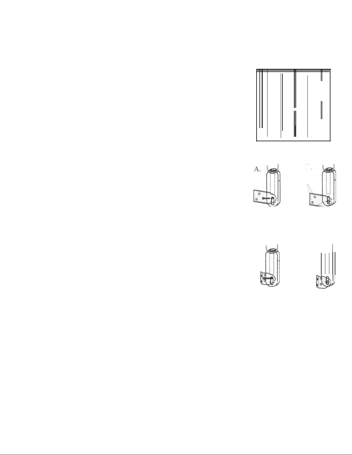
Figure 7. Inside Mount Installation
Attach Bracket
to Device
Indicator line
Mark Screw Hole
Figure 8. Outside Mount Installatioi
A.
B.
Screw Hole
Attach Bracket
to Device
Mark Screw Hole
B.
Screw Hole
11/24/10 2/2 Patent Pending
Install Device
You can install the device inside window casing with inside mount
bracket, or outside window casing with outside mount bracket. Make
sure the device is not placed in the path of the bottom rail or fabric. At
the job site, use cutting pliers to carefully snip and remove the cable tie
from the device. Slide the device to the bottom of the tool while pulling
the screw hole in the device as shown in Figure 6. The device must be
properly and securely mounted with tension on the drive loop for the
shade to be fully operatable.
Inside Mount (see Figure 7)
1. Attach the device to the inside mount bracket with the short screw as
shown in Figure 7A. The nub on the bracket fits into the back of the screw
hole on the device.
2. Pull down on the bracket, align the center of the screw hole part with
the indicator line on the device as shown in Figure 7B.
3. While holding the device firmly in place, check if the loop can move
freely through it.
1) If the device locks onto the loop, it is too loose and the bracket
and device should be moved down.
2) If the loop does not run freely through the device, it is too tight
and the bracket and device should be moved up.
4. Mark and pre-drill the screw holes.
5. Pull down on the bracket and device, align it with the drilled holes, and
mount the bracket to inside window casing with two long screws.
6. Check to ensure the loop can move freely through the device without
engaging the lock.
Outside Mount (see Figure 8)
Follow the same procedure as the inside mount from step 1 to step 4,
except outside mount bracket should be used instead of inside mount
bracket. Detach the device from the bracket by removing the short screw.
Align the bracket screw holes with the drilled holes and mount the
brackets to the wall with two long screws. Reattach the device to the
bracket with the short screw. Check to ensure the loop can move freely
through the device without engaging the lock.
Note: Bead chain connectors or stops will cause a slight jump when going through
the device. Certain brand of bead chain connectors may not work with the device.
www.HomeSewingDepot.com