HTC 2500 iX User manual

Instructions HTC 2500 iX
1 Starting Procedure
2 Maintenance Schedule
3 HTC 2500 Manual
4 HTC 2500 Education
5 Perkins 1104 Engine Manual
Particle Filter Datasheet
6 Generator Manuals
7 HTC 86D Manual
HTC 55C Manual
8 Gear Unit Manual
9
10


33
:KHQWKHHQJLQHVWDUWVUHOHDVHWKHNH\DQGDOORZLWWR
UHWXUQ
,IWKHHQJLQHGRHVQRWVWDUWUHOHDVHWKHVWDUWNH\DQG
DOORZWKHHOHFWULFVWDUWHUPRWRUWRFRRO7KHQUHSHDWVWHSV
DQG
7KHHQJLQHLQLWLDOO\UXQVDWLGOHVSHHGWRHQVXUHOXEULFD-
WLRQIRUDOOSDUWVDQGDXWRPDWLFDOO\VSHHGVXSWRZRUNLQJ
USPDIWHUDSSUR[LPDWHO\VHFRQGV/HWWKHFRQWUROGLVSOD\
Operation
7XUQWKH´,JQLWLRQ´NH\IXOO\FORFNZLVHDQGFUDQNWKHHQ-
JLQHXQWLOWKHHQJLQHVWDUWV
0
I
II
III
OK
SteeringGrinding
OFF ON
OFF ON
OFF
Off
ON
On
OFF ON
OK
VACControl
Ignition
GrindingHead
DOWN
UP
Grinding
Speed
Warning
MainPower
Electric
Power
MainpowerOn
Mainpower
SystemReady
HTC 2500 iX
OK
SteeringGrinding
OFF ON
OFF ON
OFF
Off
ON
On
OFF ON
OK
VAC Control
Ignition
Grinding Head
DOWN
UP
Grinding
Speed
Warning
Main Power
Electric
Power
Main power On
Main power
System Ready
HTC 2500 iX
ERRWXQWLO´&217,18(´FDQEHVHHQRQVFUHHQ
6WDUWWKHGXVWH[WUDFWRUDQGUHYHUVHGULYLQJFRQWUROPRQL-
WRU6HHSDJHSRV
3RVLWLRQDOOVWHHULQJDQGWXUQLQJMR\VWLFNVLQQHXWUDO
&KHFNWKDWWKHVWHHULQJJULQGLQJ9$&FRQWURODQG
JULQGLQJKHDGSRVLWLRQFRQWUROVDUHLQWKHLUFHQWUDOQHXWUDO
SRVLWLRQ
3UHVVWKH´&217,18(´EXWWRQRQWKHFRQWUROGLVSOD\
32
Operation
Starting the engine
WARNING:'RQRWXVHDHURVROW\SHVRIVWDUWLQJDLGVVXFK
DVHWKHU6XFKXVHFRXOGUHVXOWLQDQH[SORVLRQDQGSHU-
VRQDOLQMXU\
WARNING: ,I\RXQHHGWRVKXWWKHHQJLQHRIIDWDQ\WLPH
WRDYRLGLQMXU\RUGDPDJHXVHWKH(0(5*(1&<6723
EXWWRQ6LPSO\WXUQLQJRIIWKHNH\ZLOOQRWVWRSWKHHQJLQH
LPPHGLDWHO\
NOTICE:'RQRWFUDQNWKHHQJLQHIRUPRUHWKDQVHF-
RQGV$OORZWKHHOHFWULFVWDUWHUPRWRUWRFRROIRUWZRPLQ-
XWHVEHIRUHFUDQNLQJWKHHQJLQHDJDLQ
(QVXUHWKDWWKHPDLQVZLWFKVHH¿JXUHEHORZKDVEHHQ
HQJDJHGIRUDWOHDVWVHFRQGV
&KHFNWKDWWKHPDFKLQH¶VGRRUVDQGFRYHUVDUHFORVHG
DQGORFNHGVRWKDWQRSHUVRQQHOFDQEHLQMXUHG
7XUQRIIWKH&RQGLWLRQLQJVHH¿JXUHEHORZ
0
I
II
III
OK
Steering Grinding
OFF ON
OFF ON
OFF
Off
ON
On
OFF ON
OK
VACControl
Ignition
GrindingHead
DOWN
UP
Grinding
Speed
Warning
MainPower
Electric
Power
Mainpower On
Mainpower
SystemReady
HTC 2500 iX
0
I
II
III
OK
Steering Grinding
OFF ON OFF ON
OK

46
After stopping engine
WARNING:$OZD\VOHWWKHHQJLQHFRROEHIRUHLQVSHFWLQJ
WKHFRRODQWOHYHO)DLOXUHWRGRVRFDQUHVXOWLQSHUVRQDO
LQMXU\
NOTICE:2QO\XVHDQWLIUHH]HFRRODQWPL[WXUHVUHFRP-
PHQGHGLQWKHFRRODQWVSHFL¿FDWLRQVWKDWDUHLQWKH2SHUD-
WLRQDQG0DLQWHQDQFH0DQXDO)DLOXUHWRGRVRFDQFDXVH
HQJLQHGDPDJH
&KHFNFUDQNFDVHRLOOHYHO0DLQWDLQWKHRLOOHYHOEH-
WZHHQWKH³$''´PDUNDQGWKH³)8//´PDUNRQWKHRLOOHYHO
GLSVWLFN,QRUGHUWRDOORZWKHRLOWRUHWXUQWRWKHRLOSDQGR
QRWRSHUDWHWKHHQJLQHIRUDWOHDVWPLQXWHVSULRUWRWKLV
FKHFN
,IQHFHVVDU\SHUIRUPPLQRUDGMXVWPHQWV5HSDLUDQ\
OHDNVDQGWLJKWHQDQ\ORRVHEROWV
1RWHWKHUHTXLUHGVHUYLFHLQWHUYDOVIRUWKHPDFKLQH¶V
FRPSRQHQWV3HUIRUPWKHHQJLQHPDLQWHQDQFHWKDWLVVSHFL-
¿HGLQWKH2SHUDWLRQDQG0DLQWHQDQFH0DQXDO³0DLQWH-
QDQFH,QWHUYDO6FKHGXOH´3HUIRUPDOOUHTXLUHGSHULRGLF
PDLQWHQDQFHRQDOOGULYHQHTXLSPHQW
)LOOWKHIXHOWDQNLQRUGHUWRKHOSSUHYHQWDFFXPXODWLRQ
RIPRLVWXUHLQWKHIXHO7KHIXHOWDQNPD\RQO\EH¿OOHGZLWK
GLHVHOFODVV0.'RQRWRYHU¿OOWKHIXHOWDQN
$OORZWKHHQJLQHWRFRRO&KHFNWKHFRRODQWOHYHO
,IIUHH]LQJWHPSHUDWXUHVDUHH[SHFWHGFKHFNWKHFRRO-
DQWIRUWKHFRUUHFWDQWLIUHH]HSURWHFWLRQ7KHFRROLQJV\VWHP
PXVWEHSURWHFWHGDJDLQVWIUHH]LQJWRWKHORZHVWH[SHFWHG
RXWVLGHWHPSHUDWXUH,IQHFHVVDU\DGGWKHFRUUHFWFRRODQW
ZDWHUPL[WXUH
Operation
45
Stopping the engine
NOTICE:6WRSSLQJWKHHQJLQHLPPHGLDWHO\DIWHULWKDV
EHHQZRUNLQJXQGHUORDGFDQUHVXOWLQRYHUKHDWLQJDQG
DFFHOHUDWHGZHDURIWKHHQJLQHFRPSRQHQWV,IWKHHQ-
JLQHKDVEHHQZRUNLQJDWKLJKORDGVLWLVLPSRUWDQWWKDW
WKHHQJLQHLVUXQDWORZLGOHIRUDWOHDVWWKUHHPLQXWHVWR
UHGXFHDQGVWDELOLVHLQWHUQDOHQJLQHWHPSHUDWXUHEHIRUHLW
LVVWRSSHG$YRLGLQJKRWHQJLQHVKXWGRZQVZLOOPD[LPLVH
WXUERFKDUJHUVKDIWDQGEHDULQJOLIH
NOTICE:(PHUJHQF\VKXWRIIFRQWUROVDUHIRU(0(5*(1-
&<XVH21/<'2127XVHHPHUJHQF\VKXWRIIGHYLFHVRU
FRQWUROVIRUQRUPDOVWRSSLQJSURFHGXUH
3UHVVWKH0DLQ3RZHUEXWWRQ2))
7XUQWKHNH\WRWKH2))SRVLWLRQ
Operation
7KHHQJLQHZLOOUXQDWLGOHDQGVWRSVDXWRPDWLFDOO\DIWHU
WZRPLQXWHVLQRUGHUWRVWDELOLVHLQWHUQDOHQJLQHWHPSHUDWXUH
DQGPD[LPLVHWXUERFKDUJHUOLIH
0DNHVXUHWKDWGLHVHOHQJLQHLVFRPSOHWHVWRSSHG
7XUQWKH0DLQ3RZHUVZLWFKWR2))DQGUHPRYHWKHNH\
0
I
II
III
OK
Steering Grinding
OFF ON
OFF ON
OFF
Off
ON
On
OFF ON
OK
VACControl
Ignition
GrindingHead
DOWN
UP
Grinding
Speed
Warning
MainPower
Electric
Power
MainpowerOn
Mainpower
SystemReady
HTC 2500 iX
OK
Steering Grinding
OFF ON
OFF ON
OFF
Off
ON
On
OFF ON
OK
VAC Control
Ignition
Grinding Head
DOWN
UP
Grinding
Speed
Warning
Main Power
Electric
Power
Main power On
Main power
System Ready
HTC 2500 iX
1
2

Maintenance schedule
HTC 2500 iX
When required
Battery – disconnect.............................................................................HTC 2500 Manual, page 32
Engine – clean...........................................................................................Perkins Manual, page 60
Engine air cleaner element clean/replace................................................Perkins Manual, page 61
Engine oil sample – obtain .......................................................................Perkins Manual, page 64
Fuel injector – test/change.......................................................................Perkins Manual, page 68
Fuel system – prime .................................................................................Perkins Manual, page 69
Severe service application – check...........................................................Perkins Manual, page 75
Machine – clean ...................................................................................HTC 2500 Manual, page 47
Daily
Alternator and fan belts – inspect/adjust/replace...................................Perkins Manual, page 53
Cooling system coolant level – check.......................................................Perkins Manual, page 59
Driven equipment – check........................................................................Perkins Manual, page 60
Engine air cleaner element - clean...........................................................Perkins Manual, page 61
Engine oil level – check.............................................................................Perkins Manual, page 64
Fuel system primary filter/water separator – drain.................................Perkins Manual, page 70
Walk-around inpection.............................................................................Perkins Manual, page 77
Grinding heads – inspect .............................................................HTC 950 RX manual, Chapter 5.5
Hoses – inspect................................................................................................................................
Sock filters – inspect.............................................................................. HTC 86D Manual, page 10
Pneumatic system – drain ...............................................................................................................
Slide valves – check .........................................................................................................................
Electrical cabinets – check fans .......................................................................................................
Every 50 Service hours or weekly
Fuel tank water and sediment – drain .....................................................Perkins Manual, page 73
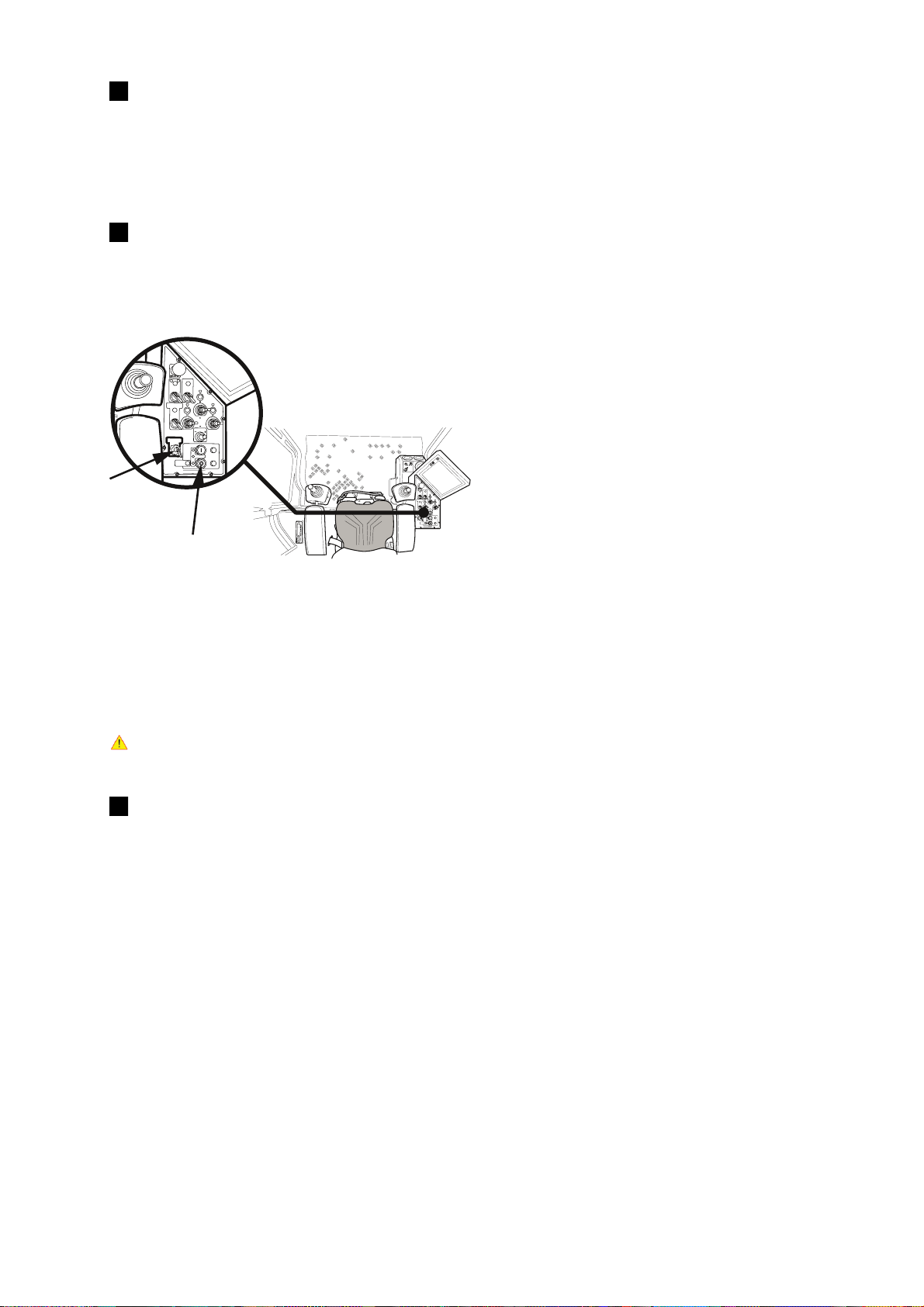
RCCDs - test ..........................................................................................HTC 2500 Manual, page 61
Circuit breakers - exercise ....................................................................HTC 2500 Manual, page 61
Dust extractors – inspect.................................................................................................................
Pre-separators – inspect..................................................................................................................
HEPA filter – inspect.............................................................................. HTC 86D Manual, page 11
Machine – clean ...................................................................................HTC 2500 Manual, page 47
Grinding heads – inspect .............................................................HTC 950 RX manual, Chapter 5.6
Grease points – lubricate ................................................................................................................
Gear unit – inspect/clean ............................................................... Gear unit Manual, Chapter 6.1

Every 100 hours or 1 year
Grinding heads – inspect .............................................................HTC 950 RX manual, Chapter 5.7
Every 250 hours or 1 year
Engine oil and filter – change ...................................................................Perkins Manual, page 65
Every 500 hours or 1 year
Engine air cleaner element – clean/replace.............................................Perkins Manual, page 61
Engine ground – inspect/clean.................................................................Perkins Manual, page 64
Fuel system primary filter (water separator) element – replace .............Perkins Manual, page 70
Fuel system secondary filter – replace.....................................................Perkins Manual, page 71
Hoses and clamps – Inspect/replace........................................................Perkins Manual, page 74
Radiator – clean........................................................................................Perkins Manual, page 75
Sock filters – replace ............................................................................. HTC 86D Manual, page 10
HEPA filter – replace.............................................................................. HTC 86D Manual, page 11
Chassie joint – inspect .....................................................................................................................
Particle filter – clean....................................................................................DPX Datasheet, page 4
Every 1000 service hours
Engine valve lash – inspect/adjust ...........................................................Perkins Manual, page 67
Every 2000 service hours
Aftercooler core – inspect ........................................................................Perkins Manual, page 52
Alternator – inspect..................................................................................Perkins Manual, page 53
Engine mounts – inspect ..........................................................................Perkins Manual, page 64
Starting motor – inspect...........................................................................Perkins Manual, page 76
Turbocharger – inspect ............................................................................Perkins Manual, page 76
Water pump – inspect..............................................................................Perkins Manual, page 78
Every 2 years
Cooling system coolant – change .............................................................Perkins Manual, page 58
Every 3000 Service hours
Fuel injector – test/change.......................................................................Perkins Manual, page 68
Every 3000 service hours or 2 years
Cooling system coolant – change .............................................................Perkins Manual, page 55
Gear unit – inspect/oil change ....................................................... Gear unit Manual, Chapter 6.1
Every 4000 service hours
Aftercooler core – clean/test ...................................................................Perkins Manual, page 52

1
Manual
GB


1
Introduction
The HTC 2500 iX is the world’s rst industrialised grinding machine. A complete, mobile grinding system in one and the same
vehicle makes the HTC 2500 iX the world’s most advanced and most efcient grinding machine ever. With a grinding width
of an impressive two and a half metres and an automatic dust separation system integrated in the machine, the HTC 2500 iX
grinding machine is in a class of its own, an industrialised grinding system for really large areas. The HTC 2500 iX is packed
with technology and features, and our designers have done everything possible to optimise the oor grinding work. And with
its on-board comforts, the machine is also incomparably more comfortable to operate from an ergonomic perspective than
other grinding machines on the market. Congratulations on your purchase of the world’s most efcient and innovative
grinding system.

2
Important information
Read through this manual carefully so that you know how to use and maintain the HTC 2500 iX before using it.
For service work other than that described in this manual, contact HTC for parts and service.
Liability
• Even though every effort has been made to make this manual as complete and accurate as possible, we bear no
responsibility for incorrect or missing information. HTC reserves the right to change descriptions in this manual without
giving prior notice.
• This manual is protected by the Copyright Act and no part of it may be copied or used in any other way without the
written approval of HTC.
Trademarks
HTC is a trademark owned by HTC Sweden AB. Other names and products mentioned in this manual may be registered
trademarks owned by the relevant companies.
© 2006 HTC Sweden AB. All rights reserved.
Travel and transport on public roads
Always check applicable road trafc provisions before travel and transportation on public roads. During transportation,
approved fastening devices must always be used and the machine must be securely anchored.

3
Contents
Introduction................................................................................................................................................1
Important information...............................................................................................................................2
Trademarks ................................................................................................................................................2
Travel and transport on public roads......................................................................................................2
Liability.......................................................................................................................................................2
Warranty.....................................................................................................................................................7
The manual.................................................................................................................................................8
Safety..........................................................................................................................................................9
Vibration and noise.................................................................................................................................10
Machine name plate ................................................................................................................................10
On delivery...............................................................................................................................................10
Example of machine name plate ........................................................................................................... 11
Unpacking the machine..........................................................................................................................12
CE marking...............................................................................................................................................12
Declaration of conformity.......................................................................................................................13
Introduction to the HTC 2500 iX.............................................................................................................14
Technical specication for the HTC 2500 iX .............................................................................................. 14
The technology and its benets ................................................................................................................. 15
Safety instructions..................................................................................................................................16
Operating the machine on a sloping surface....................................................................................................................16
Machine description – Front view..........................................................................................................17
Description of machine components – Front.......................................................................................18
Machine description – Rear view...........................................................................................................19
Description of machine components – Rear ........................................................................................20
Presentation.............................................................................................................................................21
Cab – Location of controls.................................................................................................................................................21
Presentation.............................................................................................................................................22
Cab – Function of controls.................................................................................................................................................22
Presentation.............................................................................................................................................23
System location – Left-hand side ......................................................................................................................................23

4
Presentation.............................................................................................................................................24
System description .............................................................................................................................................................24
Presentation.............................................................................................................................................25
System location – Right-hand side....................................................................................................................................25
Presentation.............................................................................................................................................26
System description .............................................................................................................................................................26
Presentation.............................................................................................................................................27
System description – Interface touch-screen...................................................................................................................27
Presentation.............................................................................................................................................28
System description – Interface touch-screen – Service..................................................................................................28
Presentation.............................................................................................................................................29
System description – CanOpen components’ status.......................................................................................................29
Presentation.............................................................................................................................................30
System description – Interface touch-screen...................................................................................................................30
Operation..................................................................................................................................................31
Before starting the engine..................................................................................................................................................31
Operation..................................................................................................................................................32
Starting the engine..............................................................................................................................................................32
Operation..................................................................................................................................................33
Operation..................................................................................................................................................34
Operating the machine........................................................................................................................................................34
Operation..................................................................................................................................................35
Driving the machine............................................................................................................................................................35
Operation..................................................................................................................................................36
Operation..................................................................................................................................................37
Grinding heads....................................................................................................................................................................37
Operation..................................................................................................................................................38
Grinding................................................................................................................................................................................38
Operation..................................................................................................................................................39
Folding up grinding head for tool replacement................................................................................................................39
Operation..................................................................................................................................................40
Tool replacement.................................................................................................................................................................40

5
Operation..................................................................................................................................................41
Mist Cooler System.............................................................................................................................................................41
Operation..................................................................................................................................................41
Grinding pressure ...............................................................................................................................................................41
Presentation.............................................................................................................................................42
Suction system....................................................................................................................................................................42
Schematic diagram..................................................................................................................................43
Suction system....................................................................................................................................................................43
Operation..................................................................................................................................................44
Suction system....................................................................................................................................................................44
Operation..................................................................................................................................................45
Stopping the engine............................................................................................................................................................45
Operation..................................................................................................................................................46
After stopping the engine...................................................................................................................................................46
Care and maintenance............................................................................................................................47
Cleaning the machine .........................................................................................................................................................47
Refuelling the diesel engine...............................................................................................................................................47
Error codes in control panel...................................................................................................................48
Frequency converter: Error code 0 - 14 ............................................................................................................................48
Error codes in control panel...................................................................................................................49
Frequency converter: Error code 15 - 28 ..........................................................................................................................49
Error codes in control panel...................................................................................................................50
Frequency converter: Error code 29 - 42 ..........................................................................................................................50
Error codes in control panel...................................................................................................................51
Frequency converter: Error code 43 - 56 ..........................................................................................................................51
Error codes in control panel...................................................................................................................52
Frequency converter: Error code 57 - 70 ..........................................................................................................................52
Error codes in control panel...................................................................................................................53
Frequency converter: Error code 71 - 73 ..........................................................................................................................53
Control cabinet - AS1..............................................................................................................................54
Control cabinet - AS1..............................................................................................................................55

6
Control cabinet - AS2..............................................................................................................................56
Control cabinet - AS3..............................................................................................................................57
Control cabinet - AS4..............................................................................................................................58
Appendix 1 – Additions to manual for HTC 2500 iX.............................................................................59
Appendix 2 – Maintenance intervals for HTC 2500 iX..........................................................................58

7
Warranty
This warranty only covers manufacturing defects. HTC bears no responsibility for damage that arises or occurs during trans-
portation, unpacking or use. In no case and under no circumstances shall the manufacturer be held responsible for damage
and defects caused by incorrect use, corrosion or use over and above the prescribed specications. The manufacturer is not
responsible for indirect damage or costs under any circumstances. The manufacturer’s warranty period is 24 months from
commissioning, although no longer than 18 months from delivery from the factory (General delivery terms NL92).
Local distributors may have special warranty terms specied in their terms of sale, delivery and warranty. If you are unsure
regarding warranty terms, please contact your retailer.

8
This symbol means Warning! and indicates a risk of personal injury or material damage in the event of incorrect use of the machine
or associated equipment.
If you see this symbol next to a section of text, you must be particularly careful when reading through the text and must not carry out
any stages of which you are unsure. This is for your own and other users’safety and to avoid damage to machinery or other equipment.
This symbol means Note! and indicates a potential risk of material damage in the event of incorrect use of the machine or associated
equipment.
If you see this symbol next to a section of text, you must be particularly careful when reading through the text and must not carry out
any stages of which you are unsure. This is to avoid damage to the machinery or other equipment.
This symbol means Tip! and indicates that, in the subsequent text, you can get tips and advice on ways to make operating your ma-
chine or associated equipment easier, and to avoid wear.
If you see this symbol next to a text, you should read through the text to make your work easier and to extend the service life of the
machine.
The manual
In addition to general functions, this manual deals with areas of application and maintenance for the HTC 2500 iX grinding
machine. A number of symbols are used in the manual to highlight the most important sections, see below. In order to avoid
both personal injury and material damage as much as possible, it is extremely important to read and understand the text next
to these symbols particularly carefully. There are also other symbols indicating practical tips. These tips are there to make it
easier to understand the machine and to get maximum benet from the grinder.

9
Appropriate breathing protection must be worn and the cab must be closed during operation.
The dust collector may not be used when grinding materials that can produce explosive gases, such as epoxy and acrylic.
If the machine is being operated indoors, the location must be well ventilated.
The machine may not be operated on slopes in excess of 10°.
The machine may not be used in environments where there is a risk of falling objects.
The machine may only be operated or repaired by personnel who have completed the necessary practical and theoretical training, and who have read this manual thor-
oughly.
The instructions in this manual must be followed in order for the CE mark to be valid.
The machine may only be used for grinding and polishing unhewn stone, terrazzo, concrete or other materials specied in this manual.
The machine may not be used in environments where there is a risk of explosion or re. Look up and follow the relevant re safety regulations before starting the grinder.
Personal protection equipment must be used – safety shoes, hearing protection, a mask, safety glasses and protective gloves.
The machine must not be started in the folded position. Only start with the rotating discs facing the oor and with the tools applied.
When replacing grinding tools, pay attention as the grinding tools and the metal discs may be hot.
When replacing grinding tools, the power must be disconnected from the machine.
The machine may not be lifted in any way other than that indicated in this manual.
When removing glue and during wet grinding, always lift up the grinding heads after grinding so that they do not stick to the oor and destroy machine parts and the oor
when restarting.
The machine must always be stored in a warm, dry area when not in use.
If the machine is stored in a cold environment, it should be left to warm up for at least two hours before use.
The machine may only be used when the splash guards are tted.
Only HTC original tools and spare parts may be used.
If the mechanical locking of the grinding heads is not working, take care when working with these.
In the event of a breakdown that prevents the machine being driven under its own power, see page 16 to release operating engines.
Contact should be made with the machine’s operator before emptying dust waste. Only work directly behind the machine, within sight of the operator’s reversing camera.
Take care inside the machine’s safety zone.
For relevant wiring diagrams, contact HTC Sweden AB.
Safety

10
Vibration and noise
The machine has been tested in accordance with the ISO 8662-4 and ISO 11202 standards for vibration and noise. For vi-
brations, the average value is 1.01 m/s², which applies when the machine is being accelerated. The sound level at the ma-
chine during operation is approx. 105 dBA. This value varies depending on the choice of tool and the type of oor. The sound
level in the operator’s environment is approx. 76 dBA. Always use hearing protection.
Machine name plate
The model number and serial number for your machine are shown on the machine name plate. This information is required
when ordering spare parts for the machine. Use the space below to make a note of the model number and serial number of
your machine for future reference.
MODEL NUMBER _______________________________________________________
SERIAL NUMBER _________________________________________________________
KEY NUMBER _______________________________________________________
On delivery
The following items will be included in the delivery. Contact your retailer if anything is missing.
• Grinding machine
• Splash guard
• Manual
• Key

11
Example of machine name plate
The machine name plate is located inside the front hatch, on
the right-hand side of the cab. The serial number can also
be found inside the left-hand hatch, on the frame above the
lifting point.
1: Serial number
2: Engine number
3: Generator number
4: Output
5: Voltage 9: Weight
6: Frequency 10: Length
7: Current 11: Height
8: Phases 12: Width
13. Address eld

12
Unpacking the machine
Check carefully to see if the packaging or machine has been damaged during delivery. If there is any sign of dam-
age, contact your retailer and report it.
Check that the delivery matches the order. If there are any discrepancies, contact your retailer.
You should carefully read through the safety instructions and the manual prior to use.
CE marking
CE marking of a product guarantees its free movement within the EU area in accordance with EU regulations. CE marking
also guarantees that the product fulls various directives (the EMC Directive and other possible requirements in so-called
directives for new procedures in accordance with these regulations). The HTC 2500 iX grinding machine carries the CE mark
in accordance with the Low Voltage Directive (LVD), the Machinery Directive and the EMC Directive. The EMC Directive
states that electrical equipment must not disturb its surroundings with electromagnetic radiation and that it must also be im-
mune to electromagnetic interference in the surroundings.
The Manufacturer’s Declaration of Conformity, which shows that the HTC 2500 iX grinding machine is harmonised with the
EMC Directive, can be found on the following pages. The HTC 2500 iX is classied for use in environments such as heavy
industry Class A.
Table of contents
Other HTC Grinder manuals