HTC DM 81 User manual

1

2
Digital Multimeter –DM 81 User Manual
I. General Instruction
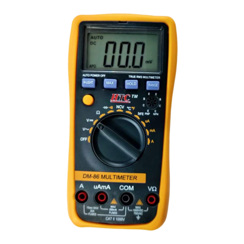
This meter DM-81 is 31/2 digital multi-function meter, which focus on large scale
integrated circuit design and A/D converter, as well as full overload protection, meter
can measure AC/DC voltage, AC/DC current, resistance, capacitance, diode forward
voltage drop, transistor hFE parameter, the transmission signal detection of infrared
remote controller (remote control) and live wire recognition.
II. Safety Precaution
This meter complies with IEC 61010-1, CAT.I 1000V standards, before operation,
please read this user manual carefully.
To avoid risk of electric shock, do not use the meter before the battery cover is in
place.
Carefully check the conditions of test leads, such as insulation, breakage or others, if
test leads is in bad condition, do not use it with the meter.
The range switch should be at right position for the testing.
To avoid electric shock and damaging the instrument, the input signals are forbidden
to exceed the specified limits.
Range switch position is forbidden to be changed at random during measurement.
To avoid electric shock, make sure max voltage between input terminal “COM” and
Earth Ground“” does not exceed over 1000V.
Take caution against shock in the course of measuring voltage higher than DC 60V &
AC 30Vrms.
Once LCD display showed ‘ ’, to change the battery to guarantee the accuracy of
measurement.
Use only moist fabric or small amount of detergent Do not use chemical solution for
cleaning the meter.
Do not store meter in high temperature and humidity conditions.
Take out of battery before storage.
III. General Description
1) DC basic Accuracy: ±1%
2) Low battery indication: “
-+
”
3) Max. display: 1999 (3 1/2 digits)
4) Auto power off: automatically powered off in 15 minutes
5) 20A input Jack: no fuse
6) mA input jack fuse: 200mA/250V fuse
7) Installed battery: 9V NEDA/6F22 or equivalent battery
8) Environmental conditions
Working Temp.: 0℃~40℃; Humidity: <80%

3
Storage Temp.: -10℃~50℃; Humidity: <85%
Accuracy Guaranty Temp.: 23℃±5℃; Humidity: <70%
IV. Specifications
1. DC Voltage
Range
Resolution
Accuracy
200mV
0.1mV
±(1.2%+5)
2V
1mV
20V
10mV
200V
100mV
1000V
1V
±(1.5%+5)
-- Input Impendency: 1MΩ@200mV&2V, effective @10MΩ for other ranges
-- Overload Protection: 250V for 200mV & 2V range, effective DC or AC 1000V for other
ranges
2. AC Voltage
Range
Resolution
Accuracy
200mV
0.1mV
±(2%+5)
2V
1mV
±(1.8%+5)
20V
10mV
±(1.5%+5)
200V
100mV
750V
1V
±(2%+7)
-- Input Impendency: 1MΩ@200mV&2V, effective @10MΩ for other ranges
-- Frequency Range: 40Hz ~ 400Hz (40Hz~100Hz @200V/700V)
-- Overload Protection: 250V for 200mV & 2V range, effective DC or AC 1000V for other
ranges
-- Response: average, calibrated in RMS of sine wave
3. DC Current
Range
Resolution
Accuracy
2mA
1μA
±(1.5%+5)
200mA
100μA
±(2%+5)
20A
10mA
±(3%+5)
-- Overload Protection: 200mA/250V fuse, 20A range without fuse
-- Max Input Current: 20A (≤10 seconds)
--
Measured by the voltage drop: full range as 200mV

4
4. AC Current
-- Overload Protection: 200mA/250V fuse,
20A range without fuse
-- Max Input Current: 20A (≤10 seconds)
-- Measured by the voltage drop: full range
as 200mV
-- Frequency Range: 40Hz ~ 400Hz
-- Response: average, calibrated in RMS of sine wave
5. Resistance
Range
Resolution
Accuracy
200Ω
0.1Ω
±(1.5%+5)
2KΩ
1Ω
20KΩ
10Ω
200KΩ
100Ω
2MΩ
1KΩ
20MΩ
10KΩ
±(2%+5)
200MΩ
100KΩ
±(5%+5)-10
-- Overload Protection: 220V effective value
-- Open circuit Voltage: <1V (200MΩ@ range 2.8V)
-- 200MΩrange short display appox.10 digits, measuring value = displayed value – 10 digits
6. Capacitance
Range
Resolution
Accuracy
20nF
10pF
±(3%+10)
200nF
100pF
2μF
1nF
200μF
10nF
±(5%+10)
-- Overload Protection: 36V or AC peak value
7. Transistor hFE Test
Range
Description
Measuring Condition
hFE
Display:
0~1000β
Ibo≈10μA,
Vce≈2.8V
Range
Resolution
Accuracy
2mA
1μA
±(2%+5)
200mA
100μA
±(2.5%+5)
20A
10mA
±(3%+7)

5
8. Diode and Continuity Test
Range
Description
Measuring Condition
Read approximate forward
voltage of diode
Forward DC current approx. as
1mA;
Inverse DC voltage approx. as
2.8V
Built-in buzzer will sound if
resistance is less than 50Ω,
display resistance approximate
value
Open circuit voltage
approximate as 2.8V
-- Overload Protection: 250V effective value
9. The transmission signal detection of infrared remote controller and live wire
recognition (△), see operation instruction.
V. Operating Instruction
Pay attention to the “ ” besides the input jack, which shows that the input voltage
or current should be within the specified value. In addition, the range switch should be
at right position for the testing.
1. Measuring DC Voltage
1> Connect the black test lead to COM jack and the red to V/Ω jack.
2> Set the rotary switch at the desired “V ” range position, connect test leads across
the source or load under
measurement, you can get reading from LCD. The polarity of the red lead connection
will be indicated along
with the voltage value.
NOTE:
a.When the value scale to be measured is unknown, set the range selector at the highest
position.
b. When only the figure’1’ is displayed, it indicates over-range situation and the higher
range has to be selected.
c.“ ” means you can’t input the voltage more than 1000V, it’s possible to show higher
voltage, but it may destroy the inner circuit or pose a shock.
d. Be cautious against shock when measuring high Voltage
2. Measuring AC Voltage
1> Connect the black test lead to COM jack and the red to V/Ω jack.
2> Set the rotary switch at the desired “V~” range position, connect test leads across the
source or load under
measurement.
NOTE

6
Refer the Measuring DC Voltage a.b.d.
a. means you can’t input the voltage more than 750V, it’s possible to show higher
voltage, but it may destroy the inner circuit or pose a shock.
3. Measuring DC Current
1> Connect the black test lead to COM jack, connect the red test lead to the mA jack once
measuring current below 200mA and connect the red test lead to 20A jack once the
measuring current is between 200mA to 20A.
2> Set the rotary switch at the desired A range position, connect the test leads in series
with the load under measurement, you can get the reading from LCD, the polarity of
the red lead connection will be indicated along with the current value.
NOTE
a. When the value scale to be measured is unknown beforehand, set the range selector
at the highest position.
b. When only the figure’1’ is displayed, it indicates over-range situation and the higher
range has to be selected.
c. The socket mA’s maximum current is 200mA.
d. Since 20A is not fused, the measuring time should be less than 10 seconds to prevent
precision from affecting by circuit heating.
4. Measuring AC Current
1> Connect the black test lead to COM jack, connect the red test lead to the mA jack once
measuring current below 200mA and connect the red test lead to 20A jack once the
measuring current is between 200mA to 20A.
2> Set the rotary switch at the desired A~range position, connect the test leads in series
with the load under measurement.
NOTE
a. Refer the Measuring DC Current a.b.c.d.
5. Measuring Resistance
1> Connect the black test lead to COM jack and red to V/Ωjack.
2> Set the rotary switch at the desiredΩrange position and connect the test leads across
the resistance under measurement.
NOTE
a. For measuring resistance above 1MΩ, the meter may take a few seconds to get
stable reading.
b. For measuring high resistance, connect the resistance to V/Ω and COM jacks to avoid
interference.

7
c. When checking in-circuit resistance, be sure the circuit under test has all power
removed and that all capacitors have been discharged fully.
d. 200MΩrange short display appox.10 digits, measuring value = displayed value – 10
digits, eg. Measuring 100MΩ, displayed value is 101.0, then the correct value will be
101.0 –1.0 = 100.0MΩ.
6. Measuring Capacitance
Connect black test lead to COM jack and red to mA jack; put the capacitance to the end
of test leads, pay attention on polarity.
NOTE
a. The meter may take a few seconds to stabilize reading, this is normal for high
capacitance measuring.
b. Do not connect an external voltage or a charged capacitance (especially high
capacitance) to the testing terminals.
c. Once the high capacitance with serious leakage or breakdown, the measuring value
will be not stable
7. Measuring Transistor hFE
1> Set the rotary switch to hFE range position.
2> Determine whether the transistor under testing is NPN or PNP and locate the emitter,
base and collector leads. Insert the leads into proper holes of hFE socket on the front
panel. Display the approximate hFE value at the testing condition of base current
Ib10uA and Vce 3V.
8. Measuring Diode
1> Connect the black test lead to “COM” jack and the red to “VΩmA ”jack. (the polarity of
red lead is ‘+’)
2> Set the rotary switch at the “ ” range position, Connect the red lead to the anode
and the black lead to
NOTE
a. If the lead connection is reversed, meter displayed over-range
b. The meter will show approximate forward voltage drop of the diode.
9. Measuring Continuity
1> Connect the black test lead to COM jack and set the rotary switch at the range
position, connect the red lead to the anode and the black lead to the cathode of the
diode under testing.
2> If resistance less than about 50Ω, built-in buzzer will be sound.

8
NOTE
Continuity test is available to check open/short of the circuit.
10. Infrared Remote Control Transmitting Signal Detection( )
Set the rotary switch to and align the emitter head vertically in line with the
infrared receiver, make sure the deviation is not more than±15o and the distance
between (1-30 cm) and press the power button of remote controller. If the red LED
glows at the same time, then the remote controller works properly.
NOTE
a. To avoid the intense light once applied this function.
b. The emitter head vertically align to infrared receiver and the deviation is not more
than±15o
11. Live Wire Recognition (△) (LINE TESTER).
Connect red test lead to V/Ωjack and black to COM jack, hold the insulation part of
black test lead and do not put into circuit under measurement; connect the red test
lead to live wire, the meter will display △, when the red test lead connect the earth
wire, the meter does not display △.
NOTE
When the circuit is not ground or in serious leakage circuit, once connect earth wire
might display△
Table of contents
Other HTC Multimeter manuals
Popular Multimeter manuals by other brands

Electrex
Electrex ZEPTO 96 Installation Instructions and Technical Information

Almemo
Almemo 2190-2 operating instructions

Daiichi Electronics
Daiichi Electronics SVLC-110L instruction manual

Fnirsi
Fnirsi 2C23T manual

LOVATO ELECTRIC
LOVATO ELECTRIC DMK 21 manual

LaserLine
LaserLine MultiMeter-Home operating instructions