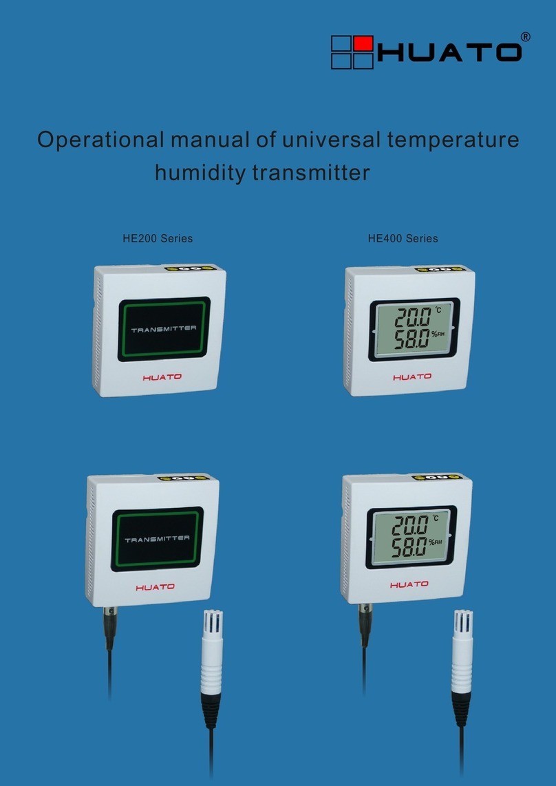
Huato HE500 Series User manual

User’s Guide
HE500 Series
Temperature & Humidity
Transmitter, wall-mounted
E-mail: [email protected]
Talk to our sales
and shop online at
www.huato.cn

The information contained in this document is believed to be correct, but HUATO accepts no liability for any errors it contains, and reserves
the right to alter specifications without notice.
www.huato.cn [email protected]
HUATO HUATO ELECTRIC CO., LTD.
Toll-Free: 0755-29977605
Customer Service: 0755-29977605
Engineering Service: 0755-29977605
Fax: +86-755-29748856
E-mail: [email protected]
Headquarters:
For Other Locations Visit www.huato.cn
South Africa:
AWR Smith Process Instrumentation CC
Web site: www.instruments.co.za

HE500 Series Table of
Contents
Table of Contents
Section
......................................................................................
Page
Section 1 Introduction ........................................................................................ 1
1.1 Introduction ................................................................................. 1
1.2 Features ........................................................................................ 1
1.3 Applications ................................................................................. 1
1.4 Data Logger Model ..................................................................... 1
1.5 Temperature and Humidity Data Logger Appearance ......... 2
1.6 Temperature and Humidity Data Logger Screen ................... 3
1.7 Button function instructions ....................................................... 5
1.7.1 - Button function instructions............................................ 5
1.7.2 - HE500A button operation instructions.......................... 5
1.7.3 - HE500M/N button operation instructions................... 7
1.8 Output Interpretation Table ...................................................... 13
2.1 Voltage........................................................................................... 14
2.2 Current ......................................................................................... 14
2.3 Modbus/RS485 ............................................................................ 15
2.4 Installation Size ........................................................................... 16
2.5 Standard MODBUS RTU Data Frames (Modbus )........... 16
Section 2 Method of Cable Installation ........................................................... 14

HE500 series temperature and humidity transmitter adopt Switzerland imported
2 in 1 sensor, the output it provides including voltage, current and modbus .etc.
With built-in high performance, lower power SCM, it provides wide range and
high precision measurements.
Section 1 - Introduction
Section 1.2 - Features
• Accuracy: Temperature/±0.5℃; Humidity/±5%RH.
• Supporting multiple standard signal output: 4-20mA /0-5V/0-10V/Modbus
/RS485,etc.
• Designed for faster heat dissipation.
• Wall-mounted.
• DC Power Supply: 9-30V.
• Host Size(L x H x D): 100mm x 100mm x 30mm.
• LCD Screen Size: 60mm x 40mm.
Section 1.3 - Application
• Museums.
• Archive room.
• Industrial and civil sectors.
There are no user serviceable parts inside your unit. Attempting to repair or service your
unit may void your warranty.
Section 1.4 - Data Logger Model
Introduction
1
NOTE:
1
HE500A-TH
HE500A-EX
-30~70℃±0.5℃
0~100%RH ±5%RH 4~20mA
0~5V
0~10V
Model Temperature
Range
Humidity
Range
Temperature
Accuracy
Humidity
AccuracyOutput
HE500V5 ±0.5℃
HE500V5-EX
HE500V10
HE500V10-EX
±0.5℃
-0~50℃
-0~50℃
-30~70℃
-30~70℃0~100%RH
0~100%RH
±5%RH
±5%RH

2
Introduction 1
Modbus
RS485
Model Temperature
Range
Humidity
Range
Temperature
Accuracy
Humidity
AccuracyOutput
HE500M
HE500M-EX
-20~70℃
±0.5℃
0~100%RH ±5%RH
HE500N ±0.5℃
HE500N-EX
-20~70℃
-40~85℃
-40~85℃0~100%RH ±5%RH
1
Section 1.5 - Temperature Data Logger Appearance
(HE500A-TH/HE500A-EX/HE500V5/HE500V5-EX/
HE500V10/HE500V10-EX/HE500M/HE500M-EX/
HE500N/HE500N-EX)
HE500A-TH
1.
2.
3.
4.
5.
6.
LCD screen
Label
Set button
Value up
Value down
Confirm button (save set
data)
Stabilizer of upper and lower covers
Venting hole
Screw holes
Threading hole
Collection of Thread hole
Connection Port
External Temperature Humidity Sensor
7.
8.
9.
10.
11.
12
13.
32 4 5 6 7 8
RANGE:-30~70℃/0~100%RH
SN:
HUATO SYSTEM CO.,LTD
HE500A2138
MODEL:HE500A-TH
10
9
9
11
12
12

Introduction
1
3
HE500V5/HE500V10/HE500M/HE500N
HE500A-EX/HE500V5-EX/HE500V10-EX/HE500M-EX/HE500N-EX
32 4 5 6 7 8
RANGE:-30~70℃/0~100%RH
SN:
HUATO SYSTEM CO.,LTD
HE500A2138
MODEL:HE500A-EX
1.
2.
3.
4.
5.
6.
LCD screen
Label
Set button
Value up
Value down
Confirm button (save set
data)
Stabilizer of upper and lower
covers
Venting hole
Screw holes
Threading hole
Collection of Thread hole
Connection Port
7.
8.
9.
10.
11.
12
32 4 5 6 7 8
RANGE:-0~50℃/0~100%RH
SN:
HUATO SYSTEM CO.,LTD
HE500A2138
MODEL:HE500V5
1
10
9
9
11
12

4
Introduction 1
1.
2.
3.
4
Alarm symbol
High limit symbol
Lower limit symbol
Set mode indicator
5.
6.
7.
8.
Baud rate indicator
Address indicator
Receive/send indicators
Temperature unit: °C or °F
9.
10.
11.
12.
Temperature value area
Humidity unit symbol
Humidity value area
Baud rate unit symbol
Section 1.6 - Temperature and Humidity Data Logger Screen
HE500A-TH/HE500A-EX/HE500V5/HE500V5-EX/HE500V10/
HE500V10-EX/HE500M/HE500M-EX/HE500N/HE500N-EX
1.
2.
3.
4.
5.
LCD screen
Label
Set button
Value up
Value down
6.
7.
8.
Confirm button
(save set data)
Stabilizer of upper and
Lower covers
Venting hole
Screw holes
Threading hole
Collection of thread hole
Connection port
External Temperature
Humidity Sensor
9.
10.
11.
12.
13.
1
10
9
9
13
11
12
1
2
3
4
5
6
7
8
9
11
10
12

Introduction
1
Section 1.7 - Button function instructions and button operation
:Press to enter SET mode when the transmitter is in normal displaying mode;
Press to get back to normal displaying mode when the transmitter is in SET mode.
:Add value (switch symbol)
:Reduce value
:Press to save temperature value and enter humidity SET mode if the transmitter
is in temperature SET mode ;
Press to save humidity value and enter normal displaying mode if the transmitter
is intemperature SET mode .
The basic flow of the HE500A setting interface is:
Temperature deviation value setting --> humidity deviation value setting --> °C / °F
switching setting.
1, HE500A power-on display instructions
The device is powered on normally and fully displayed as shown in Figure (1). After HE500A,
the version number 【V4.4】is displayed, as shown in Figure (2). After normal startup, it
enters the normal measurement state, and the screen displays the temperature value and
temperature symbol. The lower row shows the humidity value and humidity symbol, as
shown in Figure (3).
1.7.1 - Button function instructions
1.7.2 - HE500A button operation instructions
Figure 1 Figure 2 Figure 3
5

Introduction 1
2, Enter the setting interface and temperature deviation
setting
Power on the HE500A and press the 【MENU】key for 2 seconds to enter the setting
interface. As shown in Figure (1), the LCD screen displays the set temperature 【SET.T】and
the initial temperature deviation value 【0.0】. At this time, press 【UP】(【DOWN】) key to
【add】(【decrease】) the deviation value, long press to accumulate (reduced), release the
button to stop accumulating (reduced). The display interface is shown in Figure (4).
Figure 4
Figure 5
3, Humidity deviation setting
After setting the temperature deviation value, press the 【MENU】key again to select the
humidity channel deviation value setting. After entering the humidity channel deviation
value setting interface, the LCD screen displays the setting humidity 【SET.H】 and the
humidity deviation value initial value【0.0】, also perform the addition and subtraction of
the deviation value of the current channel as above, until it is set to the desired value. The
display interface is shown in Figure (5).
6

Introduction
1
°C Symbol °F Symbol
4, °C/°F Switch Settings
When the 【MENU】key is pressed again, the temperature symbol switching interface is
entered. At this time, the LCD screen displays the set temperature 【SET.°C】and the
temperature initial value symbol 【°C】; when the 【UP】/【DOWN】key is pressed, the
current temperature can be changed Symbol [°C] →[°F].
When all settings are completed, press the 【OK】key to save the setting data and the device
enters the normal measurement state.
The basic flow of the HE500M setting mode is:
Address Setting --> Baud Rate Setting --> C/F Switch Setting --> Over Temperature Alarm
Setting --> Low Temperature Alarm Setting --> Humidity High Alarm Setting - -> Humidity
under low alarm setting --> alarm switch setting --> temperature and humidity deviation
value setting.
The basic flow of the HE500N setting mode is:
C/F switching setting --> over temperature alarm setting --> low temperature alarm setting
--> humidity too high alarm setting --> humidity low alarm setting --> alarm switch Settings
--> Temperature and humidity deviation value settings.
1.7.3 - HE500M/N button operation instructions
1. HE500M/N power-on display
The HE500M/N is powered on and displayed normally as shown in Figure (1). The version
number 【V1.0】and the device address 【001】are displayed, as shown in Figure (2). After
normal startup, the device enters the normal measurement state, and the screen displays the
temperature value. And temperature symbol, the lower row shows the humidity value and
humidity No., as shown in Figure (3).
7

Introduction 1
Figure 1 Figure 2 Figure 3
2. Address settings (HE500M)
Press and hold the 【MENU】button for 50ms to enter the setting interface, as shown in
Figure (4). The LCD screen displays the setting temperature 【SET】and the setting item 【
ADR】, indicating the setting address (address), and the default address 01 is displayed in the
center of the LCD screen. At this time, press the 【UP】(【DOWN】) key to perform the
deviation value. 【Plus】(【minus】) operation, long press to accumulate (reduced), release
the button to stop accumulating (reduced), the address value is greater than zero, less than
255.
3, Baud rate setting (HE500M)
Press the 【MENU】button again to display the screen display content as shown in Figure
(5); 2. Baud rate setting. Press the 【MENU】button again, the display screen display content
is shown in Figure (5); the LCD screen displays the set temperature 【SET】and the setting
item 【BAUD】, indicating the baud rate is set. The default baud rate is 9600 (9.6Kbit/s) At
this time, press the 【UP】(【DOWN】) button to set the baud rate of 2.4 Kbit/s, 4.8 Kbit/s,
9.6 Kbit/s, and 19.2 Kbit/s. As shown in the figure, Figure (6), Figure (7), Figure (8), Figure
(9).
RANGE:-30~70℃/0~100%RH
SN:
HUATO SYSTEM CO.,LTD
HE500A2138
MODEL:HE500A-TH
Figure 4
Long press the menu button 2s
8

4, C / F switch settings
Press the 【MENU】button again, the interface will display as shown in Figure (10), the LCD
screen will display the setting temperature 【SET】and the setting item 【°C 】. At this time,
the default temperature symbol is 【°C 】, then press 【UP】(【DOWN】) button can be
used to switch between C/F.
Figure 10
Figure 7Figure 6Figure 5
Figure 9Figure 8
Introduction
1
9

6, The temperature is too low alarm settings
Press the 【MENU】button again, the interface will display as shown in Figure (12). The
LCD screen displays the set temperature 【SET】and the setting item 【LO】. At this time,
the default temperature high alarm threshold is -40.0, the symbol is 【°C 】, at this time, press
the 【UP】(【DOWN】) button to perform the 【Add】(【Decrease】) operation on the
default value, long press the accumulate (reduced), release the button to stop accumulating
(reduced) until the user The value you want to set.
Figure 1
5, The temperature is too high alarm settings
Press the 【MENU】button again, the interface will display as shown in Figure (11). The
LCD screen displays the set temperature 【SET】and the setting item 【HI】. At this time,
the default temperature high alarm threshold is 120.0 and the symbol is 【°C】. Press
the 【UP】(【DOWN】) button to perform the 【Add】(【Subtract】) operation on the
default value. Press and hold the accumulate (reduced), release the button to stop
accumulating (reduced) until the user wants to set The value is up.
Figure 11
Introduction 1
10

7, humidity is too high alarm settings
Press the 【MENU】button again, the interface will display as shown in Figure (13). The LCD
screen displays the set temperature 【SET】and the setting item 【HI】. At this time, the
default temperature high alarm threshold is 100.0, and the symbol is 【RH%】, at this time,
press the 【UP】(【DOWN】) key to perform the 【Add】(【Decrease】) operation on the
default value, long press the accumulation (reduced), release the button to stop the accumula-
tion (reduced) until the user The value you want to set.
Figure 13
8, humidity is too low alarm settings
Press the 【MENU】button again, the interface will display as shown in Figure (14). The LCD
screen displays the set temperature 【SET】and the setting item 【LO】. At this time, the
default temperature high alarm threshold is 0 0. 0, the symbol is 【RH%】, press 【UP】
(【DOWN】) at this time to perform 【Add】(【Decrease】) on the default value, long press
to accumulate (reduced), release the button to stop accumulating (reduced), until The value
that the user wants to set.
Figure 14
Introduction
1
11

10, Temperature and humidity deviation value setting
Press the 【MENU】button again, the interface will display as shown in Figure (17) and
Figure (18). In the temperature and humidity value setting interface, the user can press the
【UP】(【DOWN】) button to 【default】the value 【Plus】(【Subtract】) operation, long
press to accumulate (reduced), release the button to stop accumulating (reduced) until the
user wants to set the value.
Figure 18Figure 17
9, temperature and humidity is too high and too low alarm
settings
Press the 【MENU]】button again, the interface will display as shown in Figure (15), Figure
(16), LCD screen display setting temperature 【 SET】and setting items 【 ?】, the temperature
and humidity are too high and the alarm is too low by default. At this time, you can press the
【UP】(【DOWN】) button to perform the 【Plus】(【Subtract】) operation on the default
value to implement the switch function.
Figure 16Figure 15
Introduction 1
12

In the setting mode and temperature and humidity calibration mode, if there is no button operation in more than 20S, the device will
automatically exit the setting interface or calibration mode interface, automatically exit to the normal measurement mode, and automatically exit
the data set in the current time without saving.
Section 1.8 - Output Interpretation Table
Humidity
Temperature
0%RH 0
5V
4mA
20mA
4mA
20mA
0
5V
0
10V
0
10V
Output Type 0-5V 0-10V 4-20mA
0℃(-30)
100%RH
50℃(70)
Introduction
1
13
11, Restore factory settings (HE500M)
Press 【MENU】again to enter the factory reset interface. After pressing the 【OK】button
for 3 seconds, the user will restore the factory settings, and then automatically exit the setting
interface. The interface display is shown in Figure (19); after pressing the 【MENU】button,
Make the factory settings and exit (Note: The factory reset interface is a separate interface,
and the settings of the previous interface are not saved after pressing the 【MENU】key).
Figure 19

T_out RH_out Gnd Vcc
3 4 5 6
Temperature Output Humidity Output Negative DC Input Positive DC Input
T_out RH_out Vcc
456
Temperature Output Humidity Output Positive DC Input
Installation and Instruction 2
Section 2 - Method of Cable Installation
Section 2.1 - Voltage
Section 2.2 - Current
This section describes the installation methods of each series of HE500 products.
The name, meaning and proper wiring of each terminal are described in detail.
14

A B Gnd Vcc
1 2 5 6
485- 485+ Negative DC Input Positive DC Input
Section 2.3 - Modbus/RS485
Installation and Instruction
2
15

Installation and Instruction 2
8-Bits 8-Bits N x 8-Bits 16-Bits
Address Function Data Check
•
Section 2.4 - Installation Size
Section 2.5 - Standard MODBUS RTU Data Frames (Modbus )
70mm
70mm
67mm
5mm
8mm
4mm
16
This manual suits for next models
10
Table of contents
Other Huato Transmitter manuals