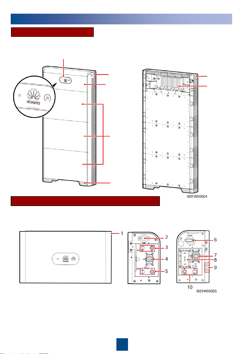
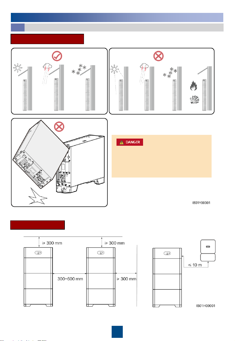
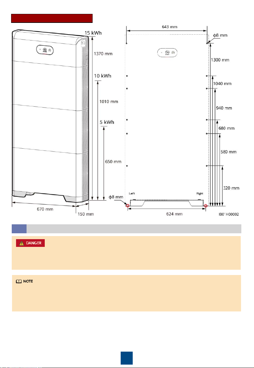
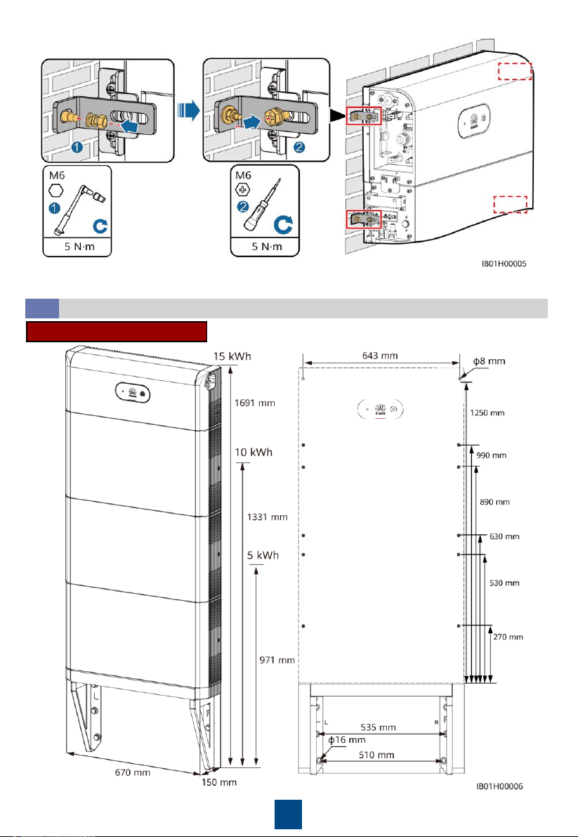
Huawei LUNA2000-NHS0 User manual

HUAWEI TECHNOLOGIES CO., LTD.
LUNA2000-(5-30)-NHS0
Quick Guide
Issue: 03
Part Number: 31500EMB
Date: 2021-05-30

1
1Product Overview
LUNA2000 Battery Appearance
Floor-
mounted
base
Power
control
module
Battery
expansion
modules
DC switch Black start
switch
Heat sink
Indicator
Note: The 15 kWh model is used as an example.
Power Control Module and Battery Expansion Modules
The LUNA2000 battery consists of a power control module and battery expansion modules. The
power control module is 5 kW, and a battery expansion module has a standard capacity of 5
kWh.
(1) Power control
module
(DCDC)
(2) Black start switch
(3) Battery terminals
(BAT+/BAT
–)
(4) COM port (COM)
(5) Battery cascading terminals
(B+/B
–)
(6) DC switch (DC SWITCH)
(7) COM port (COM)
(8) Fuse (9) Ground point
(10) Battery terminals (
BAT-
/BAT
+)
Front view Left view Right view
Copyright © Huawei Technologies Co., Ltd. 2021.
All rights reserved.
The LUNA2000 battery is applicable to the grid-tied or off-grid systems of residential rooftop PV
plants. It can store and release electric energy based on service requirements.

2
Battery Capacity Description
The battery supports power and capacity expansion. Two power control modules can be connected
in parallel. One power control module supports a maximum of three battery expansion modules.
(1) Battery expansion module
(2) Boss for alignment
(3) Battery cascading
terminals (B+/B
–)
(4) Battery cascading terminals (B+/B
–)
(5) COM port (COM)
(6) Ground point
(7) Heat sink
(8) Ground point
Front view Left view Right view
Signal cable DC input cable
5 kWh
10 kWh
15 kWh 20 kWh
25 kWh 30 kWh
*
A maximum of three battery expansion modules are supported for the JET/S-JET certification.

3
2Device Installation
Installation Requirements
2.1
Installation Environment
Installation Space
INVERTER
Do not use a dropped battery module or a
battery module that has been subjected to a
strong impact force. Otherwise, safety risks
(such as cell leakage and electric shock) may
arise.

4
Installing the Floor Support
2.2
•Avoid drilling holes in the water pipes and cables buried in the wall.
•The installation position must be far away from water sources such as taps, sewer pipes, and
sprinklers to prevent water seepage.
Mounting Hole Dimensions
First Battery PACK
DCDC (one PACK used)
DCDC (two PACKs used)
Second Battery PACK
Third Battery PACK
DCDC (three PACKs used)
The M6x60 expansion bolts delivered with the battery are mainly used for solid concrete walls and
concrete floors. If other types of walls and floors are used, ensure that the walls and floors meet
the load-bearing requirements (one battery expansion module weighs 50 kg) and select the bolts
by yourself.

5
Keep a distance of
10 mm to 15 mm
between the support
and the wall surface.
Align the
marking-off
template with the
upper surface of
the floor support.
Ground
Level Mounting holes for the
15 kWh module
Mounting holes for the
10 kWh module
Mounting holes for the
5 kWh module
Wall
Baseboard
Marking line
Pack
mounting
holes

6
Installing Battery Expansion Modules
2.3
•The following describes how to install the battery expansion modules for a 15 kWh model.
•The installation of battery expansion modules for 5 kWh and 10 kWh models is the same.
One battery expansion module is installed for a 5 kWh model, and two battery expansion
modules are installed for a 10 kWh model.
1. Install the battery expansion modules and power control module on the support.
Align the first battery
expansion module with
the support on the floor
support.
Install the connecting
pieces on both sides
and tighten the four
screws.
Install the remaining battery modules and power module from bottom to top. After
installing a module, secure the left and right connecting pieces, and then install the
next module.

7
2. Secure the power control module to the wall.
Wall-mounted Installation
2.4
Mounting Hole Dimensions
You can adjust the
connecting piece
vertically to align
with the screw holes.
3. Secure the battery expansion modules to the wall by referring to step 2.
First Battery PACK
DCDC (one PACK used)
DCDC (two PACKs used)
Second Battery PACK
Third Battery PACK
DCDC (three PACKs used)

8
Level
Wall
Ground
Mounting holes
for the 15 kWh
module
Mounting holes
for the 5 kWh
module
Mounting holes
for the 10 kWh
module
Support
For floor-mounted installation, the base is 50 mm high. If waterproofing requirements cannot be
met, the battery can be installed on a wall. The mounting kits need to be purchased separately.
For wall- and floor-mounted installation, ensure that the load-bearing capacity meets the
requirements (one battery expansion module weighs 50 kg).
Installing the Support for Wall-mounted Installation
Mounting holes for support
Pack
mounting
holes

9
18
2
Installing an Internal Ground
Cable
3.1 Installing Internal DC
Terminals
3.2
Connect the ground
points of modules in
sequence, and secure
the ground cable using
a ground screw.
•Connect cables in accordance with local installation laws and regulations.
•Before connecting cables, ensure that the DC switch on the battery and all the switches
connected to the battery are set to OFF. Otherwise, the high voltage of the battery may result
in electric shocks.
3Internal Electrical Connections of the Battery
•Internal electrical cables are delivered with the battery, see the
Packing List
in the packing case.
•The Amphenol terminal is used as the DC terminal between the power control module and the
battery expansion modules.

10
Connecting Internal Signal Cables
3.3
2
Connect cables in accordance with local installation laws and regulations.
Preparing Cables
4.1
4External Electrical Connections of the Battery
Terminal of
battery
modules
Terminal of
power
module
•When a communications terminal is connected to a single network cable, a waterproof rubber
plug must be installed. Do not install a cable with a diameter of 5 mm into a Ф7 mm rubber
plug, the 7 mm hole is used to connect to an inverter or cascaded battery.
•After inserting the terminal shell into the COM port, shake the terminal shell left and right
and pull it back to ensure that it is securely installed, and tighten the nut (ensure that the
rubber plug is tightly compressed). Otherwise, the waterproof performance is affected.
Click
Install the internal signal cables described in this section using the three signal cables with a
diameter of 5 mm and rubber plugs delivered with the DCDC. Do not use signal cables with a
diameter of 7 mm.

11
Installing a Ground Cable4.3
No.
Cable
Type
Conductor Cross
-
Sectional Area
Range
Outer Diameter
1
Ground cable
Single
-core outdoor
copper
-core cable
8 mm
2
N/A
2
DC input power cable
(inverter to battery
and battery to battery)
Common outdoor PV
cable in the industry
3.5
–5.5 mm2
5.5
–9 mm
3
Signal cable (inverter
to battery and battery
to battery)
Outdoor shielded
twisted pair cable (8
cores)
0.20
–1mm2
6.2
–7mm
Routing Cables Out of the Cable Hole
4.2
Before connecting external cables, route
the cables through the cable hole to avoid
disconnecting after installation.
Prepare cables based on site requirements.
•Ground a ground point of the power control module.
•Apply silica gel or paint around the ground terminal after the ground cable is connected.
Power control module
•Before connecting cables, ensure that the DC switch on the battery and all the switches
connected to the battery are set to OFF. Otherwise, the high voltage of the battery may result
in electric shocks.
•The DC input power cable and signal cable between the battery and the inverter must be less
than or equal to 10 m.

12
Assembling DC Connectors
Click
Positive metal
terminal
Negative metal
terminal
Ensure that the cable
cannot be pulled out after
being crimped.
Positive connector
Negative
connector
Use the wrench
shown in the figure
to tighten the
locking nut. When
the wrench slips
during the
tightening, the
locking nut has
been tightened.
Ensure that cable
polarities are
correct.
Recommended:
PV-CZM-19100
PV-MS-HZ
Open-end
wrench
Installing DC Input Power Cables
Use dedicated insulated tools to connect cables. Ensure that battery cables are connected to
correct polarities. If the battery cables are reversely connected, the battery may be damaged.
1. You are advised to connect the battery terminals (BAT+ and BAT–) on the switch side to the
inverter and connect the other side to the cascaded battery.
2. The battery terminals use the Staubli MC4 positive and negative metal terminals and DC
connectors supplied with the solar inverter. Using incompatible positive and negative metal
terminals and DC connectors may result in serious consequences. The caused device damage is
not covered under warranty.
Installing DC Input Power Cables
4.4

13
•When laying out a signal cable, separate it from power cables and keep it away from strong
interference sources to prevent communication interruption.
•Ensure that the protection layer of the cable is inside the connector, that excess core wires
are cut off from the protection layer, that the exposed core wire is totally inserted into the
cable hole, and that the cable is connected securely.
•Use a plug to block the idle cable hole with the waterproof rubber ring, and then tighten the
locking cap.
•If multiple signal cables need to be connected, ensure that the outer diameters of the signal
cables are the same.
Installing a Signal Cable
4.5
Communications Terminal Description
It is recommended that the right side of COM port be
connected to the inverter and the left side of the COM port
be connected to the cascaded batteries. The communications
terminal insertion directions on the left and right side of the
COM port are different. Insert the communications terminals
in the directions shown in the figures.
Pins 6 to 10 are close to the
groove side.
groove
groove
Connects to the battery in parallel.
The COM port on the right side connects to the inverter.

14
COM Port Pin Definitions
No.
Label
Definition
Description
1
PE
Ground point on the shield
layer
Ground point on the shield layer
2
Enable
-
Enable signal GND
Connects to the enable signal GND of the
inverter.
3
Enable+
Enable signal
+
Connects to the enable signal of the
inverter.
4
485A1
RS485A,
RS485 differential
signal+
Connects to the RS485 signal port + of the
inverter or cascaded batteries.
5
485A2
RS485A, RS485 differential
signal+
Reserved
6
485B2
RS485B, RS485 differential
signal
–
Reserved
7
485B1
RS485B,
RS485 differential
signal
–
Connects to the RS485 signal port
–of the
inverter or cascaded batteries.
8
CANL
Extended CAN bus port
Used for signal cable cascading in battery
cascading scenarios.
9
CANH
Extended CAN bus port
Used for signal cable cascading in battery
cascading scenarios.
10
PE
Ground point on the shield
layer
Ground point on the shield layer
The communications terminals on the inverter side need to be connected to RS485+\RS485-,
EN+\EN-, and PE. The communications terminals on the cascading side need to be connected to
RS485+\RS485-, EN+\EN-, CANH\CANL, and PE.
Pins 6 to 10 are close to the groove side.
groove

15
Connecting the Communications Terminal to the Inverter
Cascading Networking
(1) Communications terminal for
cascaded batteries
(2) Communications terminal
connected to the inverter
(Optional) Cable Connections in Cascading Scenarios
4.6
Insert the terminals
according to the
silkscreen number.
Pins 6 to 10 are close to
the groove side.
Click

16
Connecting the Communications Terminal for Cascaded Batteries
Cascading DC Input Connection
Prepare DC connectors and connect DC battery cascading terminals (BAT+ and BAT–) for cascaded
batteries. For details, see section 4.4 “Installing DC Input Power Cables”. The positive and negative
metal terminals and DC connectors of the Staubli MC4 for cascading need to be purchased.
Insert the terminals
according to the
silkscreen number.
Pins 6 to 10 are close to
the groove side.
4.7 Connecting Cables to the Inverter
Click
•When a communications terminal is connected to a single network cable, a waterproof rubber
plug must be installed.
•After inserting the terminal shell into the COM port, shake the terminal shell left and right
and pull it back to ensure that it is securely installed, and tighten the nut (ensure that the
rubber plug is tightly compressed). Otherwise, the waterproof performance is affected.
SUN2000-4.95KTL-JPL1

17
(1) Self-supporting output
(2) Grid-tied output
Master power
distribution panel
Specific load
power
distribution
panel

18
Battery terminals (BAT-/BAT+)
COM port (COM)
Number
Label
Definition
Description
1
OUT+
12V_OUT+
(Enable+)
Used for connecting
to the enable signal
of the battery.
2
OUT-
12V_OUT-
(Enable-)
3
A1 RS485A1
Used for connecting
to the RS485 signal
ports of the battery.
4
B1 RS485B1
5Verifying the Installation
After electrical connections are complete, check that cables are correctly and securely connected,
install the external protective cover, and secure it using screws.
Installing the Cover
5.1

19
Verifying the Installation
5.2
No.
Acceptance Criterion
1
The battery is installed correctly and securely.
2
The cables are routed properly as required by the customer.
3
Cable ties are secured evenly and no burr exists.
4
The ground cable is connected correctly and securely.
5
The battery switch and all switches connected to the battery are OFF.
6
The DC input power cables and signal cables are connected correctly and securely.
7
Idle terminals and ports are locked by watertight caps.
8
The installation space is proper, and the installation environment is clean and tidy.
Product Overview
6System Power-On
•To prevent the device from being exposed to high humidity in the power-off state, you are
advised to power on the LUNA2000 within 24 hours after unpacking it. The period for which the
device remains powered-off during maintenance must not exceed 24 hours. Otherwise,
condensation may cause damage to the device.
•After turning on the battery switch, power on the inverter. For details about how to power on
the inverter, see the quick guide for the corresponding inverter model.
•If no PV module is configured, press the black start button.
Turn on the DC switch on the battery. After the battery is installed and powered on for the first
time, the ring LED blinks for three circles. Observe the battery indicator to check the running status.
Type
Status
(blinking at long
intervals: On for 1s and then
Off for 1s; Blinking at short
Intervals:
On
for 0.2s and then
Off for 0.2s)
Meaning
Running
indication
N/A
Steady green
Steady green
Operating mode
Blinking green
at long
intervals
Blinking green
at long
intervals
Standby mode
Off
Off
Sleep mode
Blinking red
at short
intervals
N/A
Battery power control module environment alarm
N/A
Blinking red at
short intervals
Battery expansion module environment alarm
Steady red
N/A
Battery power control module fault
N/A
Steady red
Battery expansion module fault
This manual suits for next models
1
Table of contents
Other Huawei Camera Accessories manuals