Huawei PowerCube 500 User manual

Included Items
1
Horizontal Placement
Place the Camera 500 on a flat tabletop and connect the cables.
Installing the Camera 500
2
The Camera 500 can be placed horizontally, mounted on top of a display, wall-mounted,
ceiling-mounted, or placed on a tripod. Choose the best method for your site requirements.
If you have to place the Camera 500 on a sloping surface, the slope must be less 15° for the PTZ to function
properly.
Do not remove the sliding blocks from the base before installation and retain the default positions.
This list is for reference only. The delivered components may dier in appearance. The cables and power adapter
work only with the included Camera 500. If a component is damaged, missing, or wet upon being removed from
the box, contact your local supplier.
M3 x 6 Phillips flat
head machine screws
Plastic expansion bolt
(tapping screws and plastic
expansion sleeve)
Base L-shaped bracket Velcro tape strips
M3x10 screw assembly
1/4"-20 UNC screw
Standard
Optional
Camera 500 5 m network cable
Quick Start
快速入门
HUAWEI Camera 500
Quick Start
"Smart eye" cover, Securing tab
Power adapter, power cable
DIP switch plectrum
1

Mounting on Top of a Display
The Camera 500 can be mounted on top of a display if:
• Display thickness ≤ 80 mm (3.15 in.) or 100 mm (3.94 in.) < display thickness ≤ 160 mm (6.30 in.).
• The display is placed horizontally.
Use the L-shaped bracket, base, 1/4"-20UNC screw, M3x10 screw assembly, and velcro tape strips
which are delivered with the Camera 500. You need to prepare a ruler by yourself.
5Install the Camera 500 on the display.
A display thinner than or equal to 80 mm
(3.15 in.) is used as an example here.
6
1Install the Camera 500 on the base and
tighten the 1/4"-20 UNC screw.
2Measure the display thickness.
3Install the L-shaped bracket on the base. 4Stick a velcro tape strip to the
back of the display.
Display thickness ≤ 80 mm (3.15 in.) 100 mm (3.94 in.) < Display
thickness ≤ 160 mm (6.30 in.)
Pay attention to
the installation
direction of the
bracket.
• Fix the display position before installation. If the display needs to be moved after the installation, uninstall the
camera and reinstall it after the movement is complete.
• If the frame width of the display is less than 11.8 mm(0.46 in.), the front panel edge of the base may block
part of the screen.
Closely attach the
L-shaped bracket
to the back of the
display.
Do not leave a gap
between the front
panel of the base
and that of the
display.
ab
119.5 (4.70 in.) –139.5 mm (5.49 in.)
Secure the L-shaped bracket using a
velcro tape strap and tighten the
M3 x 10 screw assembly.
2
56
Hole diameter: 8 mm (0.31 in.)
Hole depth: 55 mm (2.17 in.)
12
4
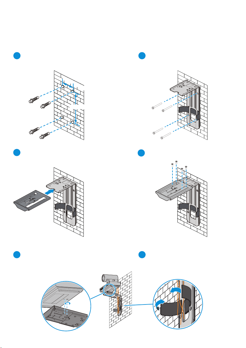
Connect the cables and route them out of the
hole in the L-shaped bracket by referring to
section "Connecting Cables".
Tie the cables together. (The color of
the cable you use may dier.)
Wall-Mounting
Secure the plastic expansion sleeves to the wall.
Install the base.
The Camera 500 can also be installed on a wall if the display is wall-mounted.
Use the included plastic expansion bolts, L-shaped bracket, base, 1/4"-20 UNC screw, and M3 x 6
Phillips flat head machine screws. You will need a hammer drill, hammer, rechargeable
battery-powered electric screwdriver, and Phillips screwdriver.
150mm (5.91 in.)
75mm (2.95 in.)
Screw the L-shaped bracket with the
tapping screws.
Screw the base with M3 x 6 Phillips flat
head machine screws.
3
3

14.5 mm (0.57 in.)
101.5mm (4 in.)
Screw hole depth: 4.0 mm (0.16 in.)
Use 1/4"-20 UNC screws.
Location hole
Diameter: 4.3 mm (0.17 in.)
Ceiling Mounting
Mount the camera on the ceiling with a self-purchased bracket. The bracket must meet the following
requirements:
• A minimum weight load of 10.5 kg (23.15 lb) and a thickness of 2 mm (0.08 in.) to 3 mm (0.12 in.).
• Comes with a location pillar, which can be inserted into the location hole of the Camera 500. The
distance between the screw hole on the bracket and the location pillar must be 14.5 mm (0.57 in.),
which is also the distance between the two holes at the bottom of the Camera 500.
• A screw hole and one 1/4"-20 UNC screw.
You can also secure the Camera 500 with a tripod. The minimum weight load of the tripod must be
10.5 kg (23.15 lb). Its mounting platform must match the bottom of the Camera 500.
Mount the purchased bracket on the ceiling as needed, and then install the Camera 500 on the bracket.
Mounted on a Tripod
When securing the Camera 500, use the 1/4"-20 UNC screw included with the purchased bracket to avoid a
mismatch.
Installing and Using the "Smart Eye" Cover
5
3
1
Understand the "smart
eye" cover.
Attach the adhesive side of the
securing tab to the left side of
the Camera 500. To disable the
"smart eye", attach the "smart
eye" cover on the "smart eye".
To enable the "smart eye",
attach the "smart eye"
cover to the securing tab
to prevent the cover from
being lost.
23
"Smart eye" cover: attracted
with magnetic force
Securing tab: attached using
adhesive
"Smart eye" cover Securing tab
4

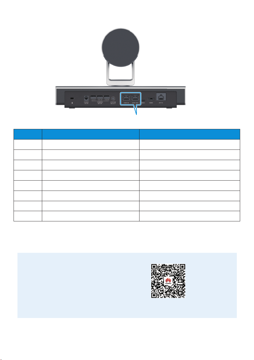
Connecting Cables
4
Performing a Power-on Check
5
Running On standby Hardware
error
Software
error
Overheated
Steady
green
Blinking green,
gradually brighter
or dimmer
Breathing light
Slowly
blinking red
(once/
5 seconds)
Rapidly
blinking red
(4 times/
second)
Blinking red
(twice/
5 seconds)
After the cables are connected, power on the Camera 500. The power indicator turns green and the
Camera 500 starts automatically.
Starting
O
Blinking green
(twice/second)
• Connect the Camera 500 to the Box 600 through an HT-TX port.
Rapidly blinking
green
(4 times/
second)
Upgrading...
Indicator
Powered
o
Status
• Connect the Camera 500 to the Box 300 through an HDMI port.
Do not manually rotate the camera PTZ or prevent it from rotating when the
Camera 500 is being powered on or running.
Network
cable
Power
cable
Power
adapter
Box 300
Network
cable
HDMI cable
SIPNO.
081599990
!
Box 600
SIPNO.
081599990
!
5

Setting the Camera 500
6
You can set camera parameters by using the two-state DIP switch or round DIP switch.
• The following table lists the functions of the two-state DIP switch.
• The following table lists the video output resolutions corresponding to the numbers of the round
DIP switch.
No.
Resolution
9
4K60
8
4K50
7
4K30
6
4K25
5
1080P60
4
1080P50
3
1080P30
2
1080P25
1
720P60
0
720P50
1
2
3
4
5
6
7
8
9
10
11
12
Auto-Framing is disabled.
Auto-Framing is enabled.
HDR is disabled.
HDR is enabled.
Standard installation
Inverted Installation
The left/right switching of the output image is disabled.
The left/right switching of the output image is enabled.
Color depth switching is not supported. (The default color depth is 8-bit.)
Color depth switching between 8-bit and 10-bit is supported.
The RGB video format is supported.
The YUV420 video format is supported.
Video output in auto resolution is disabled.
Video output in auto resolution is enabled.
50 Hz grid frequency is supported.
60 Hz grid frequency is supported.
The RJ45 IN RS-232 level is supported.
The RJ45 IN RS-422 level is supported.
No. Parameter Switch Status Function
Reserved
Reserved
Reserved
O
On
O
On
O
On
O
On
O
On
O
On
O
On
O
On
O
On
O
On
O
On
O
On
AUTO FRAME
HDR SW
FLIP
LR SW
COLOR DEPTH
420 SW, RGB
232 SW, 422 SW
Reserved
Reserved
Reserved
FIXED
RESOLUTION
PWR FR 60,
PWR FR 50
6

Controlling the Camera 500
7
You can control the PTZ and lens of the Camera 500 on the web interface of an UHD video
conferencing endpoint or Touch.
To control the Camera 500 from an endpoint that is connected to the Camera 500 through an HDMI
port, you need to add a serial cable between them.
Appendix
8
Dimensions (H x W x D)
Front Side
Top Top
86mm (3.39 in.)
30°
30°
290mm (11.42 in.)
140mm (5.51 in.)
171mm (6.73 in.)
179.5mm (7.07 in.)
7
Pin Layout
No. COM IN (RJ45) COM OUT (RJ45)
1
2
3
4
5
6
7
8
RS422_TXD-
RS422_TXD+
RS422_RXD-/RS232_RX
GND
GND
RS422_RXD+/RS232_TX
IR-OUT
NC
RS422_RXD-
RS422_RXD+
RS422_TXD-
GND
GND
RS422_TXD+
NC
NC
Scan the
QR Codes
Camera 500 Installation Video
8
Other manuals for PowerCube 500
3
Table of contents
Other Huawei Webcam manuals


