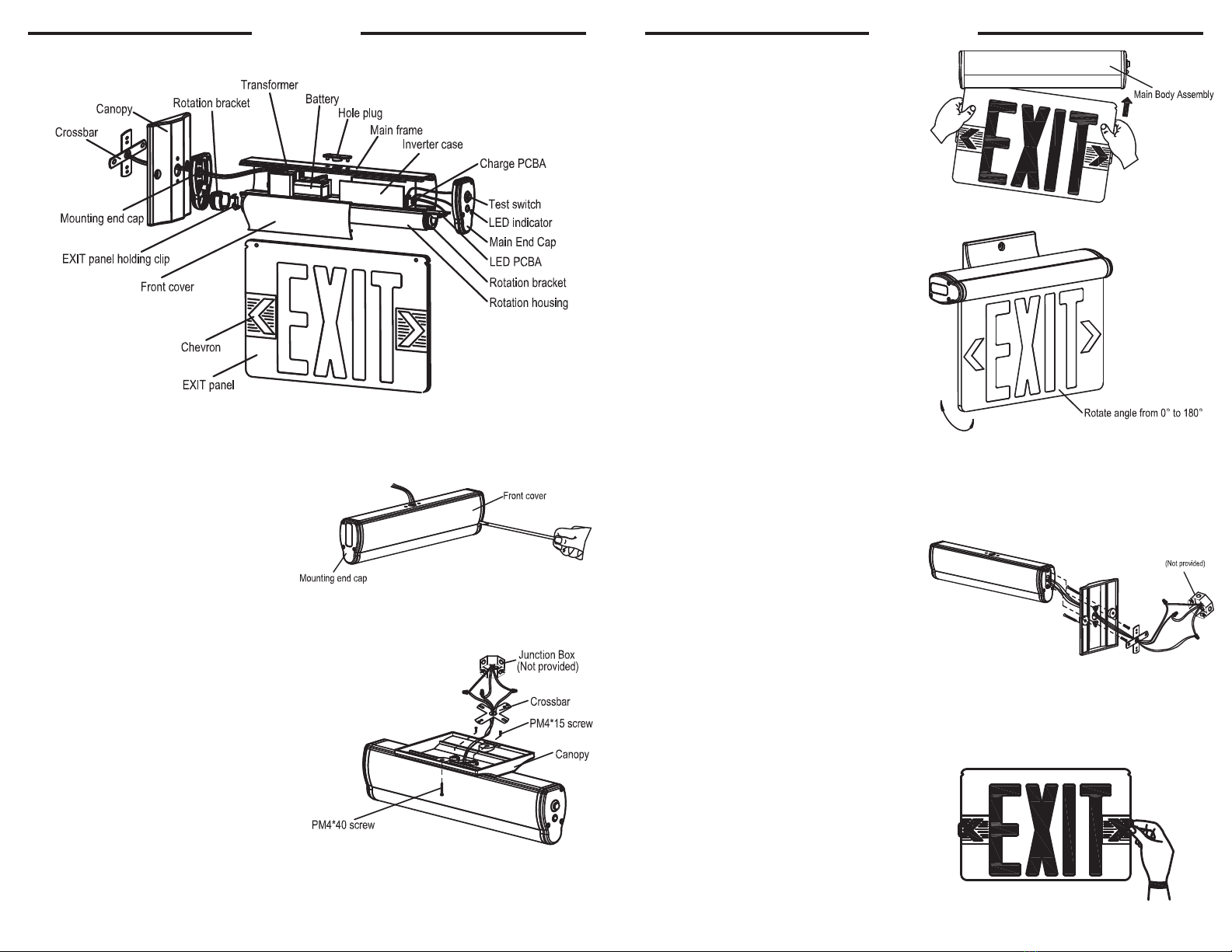
INSTALLATION INSTALLATION
1. Attach crossbar to junction box, using screws
if needed (screws are not provided)
2. Use screwdriver to open front cover to
connect battery connector.
6. Insert EXIT panel into main body assembly
gently. If EXIT panel is for single face, make
sure EXIT letter direction is correct.
3. Feed AC supply wires through canopy center hole.
4. Assemble canopy onto main body assembly
with (2) PM4*15 screws (supplied) and make
wire connections.
(See ELECTRICAL CONNECTIONS)
5. Use (2) PM4-40 screws (supplied) tighten
canopy to crossbar.
7. Determine direction for chevron placement.
(See DETERMINE DIRECTION)
8. The unit can be installed on any surface.
You may rotate the EXIT panel in any angle
from 0° to 180°. Ceiling mounting rotate 90°
become wall mounting.
NOTE: FIRST TURN OF ELECTRICITY
SURFACE CEILING & WALL MOUNTING
SURFACE END MOUNTING
1. Attach crossbar to junction box, using screws
if needed. (Screws are not provided)
2. Use screwdriver open front cover to connect
battery connector.
3. Remove the hole plug from mounting end cap.
4. Pull out all AC supply wires and feed wires
thru the center hole of mounting end cap and
then canopy.
5. Reference 4-7 step in surface ceiling and wall
mounting above for surface end mounting.
6. The unit can be installed on any surface, you
may rotate the EXIT panel in any angle from
0° to 180°.
ASSEMBLY DRAWING
DETERMINE DIRECTIONS
1. If indicator chevron is required, maintain
chevron and remove locator template.
2. If indicator chevron is not required, remove
both the chevron and locator template.


