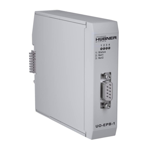
Hubner UO-SPN-1 Quick guide

English
Translation of the original operating and assembly instructions Edition: 03 2021
ID 76621
Operating and configuration instructions
UO-SPN-1 PROFINET module
PROFINET IO interface and PROFIsafe profile
U-ONE®-SAFETY-LWL
Universal encoder system –Generation II
Read the configuration manual before completing assembly,
starting installation and carrying out other work.
Store the manual for future use.
GermanGerman

UO-SPN-1
Operating and configuration manual
2
UO-SPN1_Manual-en_R4
Manufacturer / Publisher
Johannes Hübner Phone: +49 641 7969 0
Fabrik elektrischer Maschinen GmbH Fax: +49 641 73645
Siemensstr. 7 Internet: www.huebner-giessen.com
35394 Giessen / Germany E-Mail: info@huebner-giessen.com
Further current information on this product series can be found online in our Service Point.
Simply scan the QR Code and open the link in your browser.
These instructions and the enclosed declaration of conformity can also be accessed via our Ser-
vice Point. For this purpose, the QR code on the type plate of the corresponding device must be
scanned.
Trademarks
PROFIBUS™, PROFINET™ and PROFIsafe™, and their associated logos, are registered trade-
marks of PROFIBUS Nutzerorganisation e.V. (PNO).
SIMATIC is a registered trademark of SIEMENS AG.
Brand names and product names are trademarks or registered trademarks of their respective
owner. Protected trademarks bearing a ™ or ® symbol are not always depicted as such in the
manual. However, the statutory rights of the respective owners remain unaffected.
Copyright
It is strictly forbidden to reproduce this publication or parts of this publication in any form or by any
means without the prior written permission of Johannes Hübner Fabrik elektrischer Maschinen
GmbH. Content information, text, drawings, graphics, and other representations are protected by
copyright and are subject to commercial property rights. Duplications of any kind that are not com-
bined with use of the machine are prohibited without manufacturer's written consent. Actions to the
contrary make damage compensation mandatory.
Copyright© Johannes Hübner Fabrik elektrischer Maschinen GmbH
Change reservation
The manual has been drawn up with the utmost care and attention. Nevertheless, we cannot
exclude the possibility of errors in form and content.
All rights, subject to errors and changes due to technical improvements reserved.
Writing styles
Cursive or bold texts indicate the title of a document, or are used for emphasis.
Courier-New font indicates text that is visible on the screen and software or software menu selec-
tions.

UO-SPN-1
Operating and configuration manual
UO-SPN1_Manual-en_R4
3
Table of Contents
1General information.........................................................................................................6
1.1 Information on the Operating and assembly manual...................................................6
1.2 Scope of delivery........................................................................................................6
1.3 Explanation of symbols...............................................................................................6
1.4 Warranty and liability...................................................................................................7
1.5 Organisational measures............................................................................................7
1.6 Copyright protection....................................................................................................7
1.7 Warranty provisions....................................................................................................7
1.8 Customer service........................................................................................................7
2Basic safety information.................................................................................................8
2.1 Responsibility of the operator......................................................................................8
2.2 Selecting and qualifying personnel; basic obligations .................................................8
2.3 Proper use..................................................................................................................8
2.4 Improper use ..............................................................................................................9
2.5 Safety information.......................................................................................................9
3Assembly .......................................................................................................................10
3.1 Safety information.....................................................................................................10
3.2 Basic regulations ......................................................................................................10
3.3 Replacing function modules......................................................................................10
4Technical data and functions .......................................................................................11
4.1 Type plate.................................................................................................................11
4.2 Type designation ......................................................................................................11
4.3 Electrical data...........................................................................................................11
PROFINET IO transmission technology, cable specification ..............................12
4.4 Operating statuses and displays...............................................................................13
Module status display.........................................................................................14
Bus status indicator............................................................................................14
5PROFINET IO / PROFIsafe –Commissioning ..............................................................15
5.1 PROFINET IO...........................................................................................................15
Device classes...................................................................................................15
Device description file (XML)..............................................................................15
Device identification...........................................................................................15
Address assignment ..........................................................................................16
5.2 Start-up on the PROFINET IO ..................................................................................17
5.3 Configuration............................................................................................................17
Safety-related data, “AMPN(H)41 E/A safety” module........................................17
Non safety-related process data ........................................................................24
5.4 Configuration............................................................................................................25
F-Parameter (F_Par)..........................................................................................26
iParameter (F_iPar) ...........................................................................................27
6Determining the parameters / CRC calculation ...........................................................29
6.1 iParameter................................................................................................................29
CRC calculation via the iParameter....................................................................30

UO-SPN-1
Operating and configuration manual
4
UO-SPN1_Manual-en_R4
6.2 F-Parameter .............................................................................................................31
Non-adjustable F-Parameters............................................................................32
Adjustable F-Parameters ...................................................................................32
7Create security program - Example configuration......................................................33
7.1 Requirements...........................................................................................................34
7.2 Hardware configuration.............................................................................................35
Set the hardware configuration properties..........................................................39
7.3 Configuration............................................................................................................45
Setting the iParameters......................................................................................45
Setting the F-parameters ...................................................................................46
7.4 Setting the missing (F) modules................................................................................47
Program structure..............................................................................................48
F runtime group..................................................................................................48
Generating object modules (OBs)......................................................................48
Generating the functions (F-FCs).......................................................................49
Programming the F-modules..............................................................................50
7.5 Generating the security program...............................................................................53
7.6 Load security program..............................................................................................53
7.7 Test security program...............................................................................................54
8Access to the safety-related data channel...................................................................54
8.1 Output of passivated data (substitute values) in case of an error..............................54
8.2 F-periphery DBs........................................................................................................54
Measurement system F-periphery DB “DB1638” - Overview of variables...........55
8.3 Access to variables of the F-periphery DBs ..............................................................57
8.4 Measurement system - Passivation and operator acknowledgement........................58
After starting up the F system ............................................................................58
After communication errors................................................................................58
9Preset function ..............................................................................................................59
9.1 Procedure:................................................................................................................59
10Troubleshooting and diagnostics ................................................................................60
10.1 Visual displays..........................................................................................................60
Device Status.....................................................................................................60
Bus Status .........................................................................................................61
PORT1; PORT2.................................................................................................62
10.2 PROFINET IO diagnostics........................................................................................62
Diagnostic alarm................................................................................................62
Diagnosis via record data...................................................................................62
10.3 Data status ...............................................................................................................63
10.4 Return of Submodule Alarm......................................................................................63
10.5 Information & maintenance.......................................................................................64
I&M0, 0xAFF0....................................................................................................64
11Functional safety...........................................................................................................65
11.1 Safety parameters ....................................................................................................65
11.2 Reliability parameters for the SPB ............................................................................65

UO-SPN-1
Operating and configuration manual
UO-SPN1_Manual-en_R4
5
11.3 Information on functional safety ................................................................................65
Safety function principle.....................................................................................65
Safe state...........................................................................................................66
Required security reviews / measures................................................................66
12Inspections ....................................................................................................................67
12.1 Maintenance information...........................................................................................67
13Transportation, packaging and storage.......................................................................67
13.1 Transportation safety information..............................................................................67
13.2 Incoming goods controlling .......................................................................................67
13.3 Packaging (disposal).................................................................................................67
13.4 Storing packages (devices).......................................................................................67
13.5 Returning equipment (repair/goodwill/warranty)........................................................67
13.6 Disposal....................................................................................................................67
14Documents.....................................................................................................................68
14.1 Dimensional drawing.................................................................................................68
14.2 Wiring diagram..........................................................................................................69

UO-SPN-1
Operating and configuration manual
6
UO-SPN1_Manual-en_R4
1 General information
1.1 Information on the Operating and assembly manual
This operating and assembly manual provides important information for using the UO-SPN-1
electronic function module. It must be read carefully before beginning any work and observed.
The UO-SPN-1 electronic function module is referred to in the following documentation as the
SPN.
Furthermore, the local accident prevention regulations and general safety regulations applicable
for the area where the device will be used must be observed.
1.2 Scope of delivery
The scope of delivery for the function module includes the operating and configuration manual
and the software & support CD.
1.3 Explanation of symbols
Warning information is designated using symbols. Information is proceeded by signal words
which express the extent of the danger involved. Always comply with these notices, and use
caution to avoid accidents, personal injury and property damage.
WARNING!
Indicates a potentially hazardous situation that could lead to death or severe in-
jury if it is not avoided.
CAUTION!
Indicates a potentially hazardous situation that could lead to minor or slight inju-
ries if it is not avoided.
CAUTION!
Indicates a potentially hazardous situation that could lead to property damage if it
is not avoided.
NOTE!
Emphasises useful tips and recommendations, and provides information useful
for efficient, smooth operation.
!

UO-SPN-1
Operating and configuration manual
UO-SPN1_Manual-en_R4
7
1.4 Warranty and liability
Only the “General Terms and Conditions” of Johannes Hübner Fabrik elektrischer Maschinen
GmbH apply. These will be provided to the operator at the latest when the order is confirmed or
when the contract is concluded. All warranty and liability claims for personal injury and property
damage are excluded, and the operator's operating permit will be null and void if one or more of
the following apply:
Failure to observe the operating and assembly manual.
Improper use of the function module.
Improper assembly, installation, commissioning and programming of the function module.
Operating the function module despite technical defects.
Independently carrying out mechanical or electrical modifications to function modules.
Independently carrying out repairs.
Catastrophes due to external interference or force majeure.
Use of non-qualified personnel.
Opening the function module.
1.5 Organisational measures
The operating and assembly manual must always be stored easily within reach in the area
where the function module is used.
In addition to the operating and assembly manual, general statutory and other binding
regulations on accident prevention and environmental protection must be observed.
Operators must be trained on these regulations.
Applicable national, local, and system-specific provisions and requirements must be
observed.
The operator is obligated to inform personnel of special operating considerations and
requirements.
The type plate and any prohibitions or notice signs adhered to the function modules must
always be legible.
Repairs may only be carried out by the manufacturer, or by an agency or individual
authorised by the manufacturer.
1.6 Copyright protection
NOTE!
Content information, texts, drawings, images, and other illustrations are copyright
protected and subject to industrial property rights. Copying of any kind not asso-
ciated with use of the function module is prohibited without a written declaration
from the manufacturer. Violations will result in claims for damages.
1.7 Warranty provisions
Warranty provisions are outlined in the manufacturer's General Delivery Conditions.
1.8 Customer service
Contact persons are available by phone, fax, or e-mail for technical questions. See the manu-
facturer’s address on page 2.

UO-SPN-1
Operating and configuration manual
8
UO-SPN1_Manual-en_R4
2 Basic safety information
DANGER!
This section provides an overview of all significant safety aspects necessary to
protect personnel and ensure safe, fault-free operation of the function module.
Failure to observe this information may result in significant danger.
2.1 Responsibility of the operator
The function modules are used in a commercial capacity. The operator of the function modules,
therefore, is subject to statutory occupational safety requirements and the safety, accident pre-
vention and environmental regulations applicable to the areas in which the function modules are
used.
2.2 Selecting and qualifying personnel; basic obligations
All work on function modules may be carried out only by qualified personnel. Qualified per-
sonnel are personnel with the training, experience, and instruction, as well as expertise on
relevant standards, specifications, accident prevention regulations and operating circum-
stances necessary to carry out the required work, and who have been authorised to do so
by the persons responsible for the safety of the system. They are able to identify and avoid
potential hazards.
In addition, please see standards VDE 0105-100 and IEC 364 for the definition of “qualified
personnel” (reference, e.g. Beuth Verlag GmbH, VDE-Verlag GmbH)
Responsibilities for assembly, installation, commissioning and operation must be clearly de-
fined. Personnel who are receiving instruction or training must be supervised.
2.3 Proper use
The SPN must be used in conjunction with the USL(H) 42 basic device and the UO-SCU.
The system manufacturer must review whether the properties of the function module fulfil the
safety requirements in its specific application. The system manufacturer is responsible for use of
the function module and for deciding whether to use the module. Function modules are de-
signed for unsupervised, continuous operation.
Proper use also includes:
observing all information in this operating and assembly manual
observing type plates and any prohibition or information signs
observing the operating manual of the machine or system manufacturer
operating the function module within the limits stipulated in the technical data
not engaging in improper use

UO-SPN-1
Operating and configuration manual
UO-SPN1_Manual-en_R4
9
2.4 Improper use
WARNING!
Danger of death, physical injury and property damage due to improper use of the
function module!
In particular, the following uses are prohibited:
Use in environments with an explosive atmosphere.
Use in environments with radioactive radiation.
Use on ships.
Use for medical purposes.
2.5 Safety information
WARNING! ATTENTION! NOTE!
Destruction, damage or impact to the function of the function module.
Only complete wiring work and only connect or disconnect electrical connections
when the module is powered down.
Review any potential hazards due to interactions with other systems and devices
currently installed in the surrounding area, or which are to be installed. The user
is responsible for taking relevant measures.
The power supply must be secured with a fuse appropriate for the diameter of the
intake line.
Cables used must be suitable for the temperature range.
Defective function modules may not be operated.
Opening function modules is prohibited.
The type plates specify the technical properties of the function modules. If a type
plate is no longer legible, or if a type plate is missing entirely, the function module
may not be operated. Contact Hübner service (see page 2).
NOTE!
Disposal:
If the function module needs to be disposed after its service life, applicable na-
tional regulations must be observed.

UO-SPN-1
Operating and configuration manual
10
UO-SPN1_Manual-en_R4
3 Assembly
3.1 Safety information
WARNING!
Assembly and disassembly may only be carried out by qualified personnel.
In general, the requirements and acceptance conditions for the system as a
whole must be observed.
DANGER! ATTENTION!
Danger of death, severe physical injury and/or property damage due to
deactivating safety functions, caused by an unsecured shaft drive.
In general, the requirements and acceptance conditions for the system as a
whole must be observed.
3.2 Basic regulations
WARNING!
Power and signal lines must be installed separately.
Observe the manufacturer’s information when installing converters, shielding on
power lines between the frequency converter and motor.
Ensure the energy supply is sufficient for the application.
3.3 Replacing function modules
When replacing function modules, observe the following:
The new function module must have the same item no. (ID) as the old one.
When using a new measurement system, the operator must ensure that the PROFIsafe tar-
get address set via hardware switches is the same as the previous address.
Since the F parameter and iParameter of the measurement system are saved in the secu-
rity program for the controller, the new measurement system is configured with the project-
specific settings in the start-up phase.
If the project does not support neighbourhood detection, then the previously assigned de-
vice names must be assigned to the new measurement system as well during the ex-
change. The device name is recognised when the system starts up, and the new MAC ad-
dress and IP address are automatically assigned to the device name.
When recommissioning the replaced function module, a secure test run must be completed
first to ensure it functions correctly.
!

UO-SPN-1
Operating and configuration manual
UO-SPN1_Manual-en_R4
11
4 Technical data and functions
4.1 Type plate
The following image shows an example of a type plate.
The type plate is located on the outside of
the housing, and includes the following
information:
Manufacturer
Type, year of construction
CE mark
Serial number (S/N)
Protective class
Power consumption
ID number
Liquidation
MAC address
Certification information
4.2 Type designation
UO-SPN -1
SPN function module
1: Variation 1
4.3 Electrical data
Information
Value
Supply voltage
Delivered to the SCU module via the bus connector
Additional UO-SPN-1 module
power consumption
< 4 W
Overall resolution
28 Bit
Protective class in accordance
with DIN EN 60529
IP20 for cabinet installation
Degree of protection of cabinet: ≥ IP54
Singleturn functional
13 Bit (8192 steps/revolution)
Singleturn safety-specific
8 Bit (256 steps/revolution)
Multiturn
15 Bit (32768 revolutions)
PROFINET IO interface
in accordance with IEC 61158 and IEC 61784
PROFIsafe profile
3.192b in accordance with IEC 61784-3-3
Fig. 4-1: Type plate (example)

UO-SPN-1
Operating and configuration manual
12
UO-SPN1_Manual-en_R4
Information
Value
Additional functions
Preset
Parameter
Configurable via PROFINET IO
Integration time Safe
50 ms…500 ms
Integration time Unsafe
5 ms…500 ms
Monitoring window size
50…4000 increments
Standstill tolerance preset
1…5 increments/integration time Safe
Counting direction
Forward, reverse
PROFINET specifications
V2.2
Software stack
V3.2.0.1
Conformance Class
Conformance Class B, C
Physical Layer
PROFINET 100Base-TX, Fast Ethernet, ISO/IEC
8802-3
Output code
Binary
Cycle time
1 ms (IRT / RT)
Transmission rate
100 MBit/s
Transmission
CAT-5 cable, shielded (STP), ISO/IEC 11801
Addressing (configurable via
PROFINET IO)
By name (name assignment via project management
software). Name assignment -->MAC during start-up
Cycle time
Not safety-related
0.5 ms, output via JHG-PROFIBUS module
Safety-related
5 ms, output via JHG-PROFIsafe module
Preset write cycles
4 000 000
Connection technology
M12 plug
Wiring diagram
PN165-413 (see section 14.2)
Elevation above sea level
≤ 3000 m
PROFINET IO transmission technology, cable specification
Safety- related PROFIsafe communication, as well as PROFINET communication, are transmit-
ted via the commonly used network.
PROFINET supports line, tree and star structures. The bus or line structure used in field buses,
therefore, is also available for Ethernet. This is especially practical when wiring systems, since

UO-SPN-1
Operating and configuration manual
UO-SPN1_Manual-en_R4
13
lines and stubs can be combined. Since the US 42-PROFINET module already has an inte-
grated switch, the line topology can be easily created.
Only cables and plug connectors for which the manufacturer has issued a PROFINET manufac-
turer declaration may be used. Line type A/B/C, mechanical and chemical properties, and the
design of the PROFINET cable must be selected according to the automation task in question.
The cables must be designed for bit rates of up to 100 MBit/s. The transmission speed is de-
tected automatically by the USC 42 PROFINET module, and does not have to be set using a
switch.
Bus addressing via switches, as in the PROFIBUS-DP, is likewise not necessary, as this is han-
dled automatically by the addressing features of the PROFINET controller, however, the
PROFIsafe target address “F_Dest_Add” must be set, see section 5.4.1.6.
The cable length, including patch cable, may be a max. of 100 m for copper cabling between
two devices. This transmission path is defined as the PROFINET-End-to-end-link. The number
of detachable connections within the end-to-end-link is limited to six pairs of plug connectors
(plug/socket). If over six pairs of plug connectors are required, the maximum permitted damping
values (channel class D values) for the entire transmission path must be complied with.
NOTE!
With IRT communication, the topology is planned in a wiring table. Ports 1 and 2
must be connected correctly.
This is not the case for RT communication, which can be wired freely.
4.4 Operating statuses and displays

UO-SPN-1
Operating and configuration manual
14
UO-SPN1_Manual-en_R4
Module status display
Operating status
Status LED
Bus status
Start
flashing yel-
low/green
2 Hz
not
ready for oper-
ation
normal
green
ready for oper-
ation
bootloader
flashing yellow/red
1 Hz
not
ready for oper-
ation
Warning
flashing yellow
1 Hz
ready for oper-
ation
Fault
red
Fault
Warning:
A warning is generated when the SPN reaches the end of its service life (20 years).
Bus status indicator
ON
OFF
FLASHING
Device Status
No supply, hardware fault
Ready for operation
Operator acknowledgement requested, 3x 5 Hz
System or security error
Bus Status
No errors
Parameter or F-parameter error; 0.5 Hz
No connection to the IO controller
PORT 1
green
Ethernet connection formed
yellow
Data transmission TxD/RxD
PORT 2
green
Ethernet connection formed
yellow
Data transmission TxD/RxD
For appropriate measures in case of a fault, see section 10.

UO-SPN-1
Operating and configuration manual
UO-SPN1_Manual-en_R4
15
5 PROFINET IO / PROFIsafe –Commissioning
5.1 PROFINET IO
Important information on commissioning is provided in the
PROFINET commissioning guidelines, order no.: 8,081
This and further information on the PROFINET or PROFIsafe is available from the office of the
PROFIBUS user organisation:
PROFIBUS Nutzerorganisation e.V.
Haid-und-Neu-Str. 7
Phone:
+ 49 721 96 58 590
D-76131 Karlsruhe
Fax:
+ 49 721 96 58 589
www.profibus.com
E-mail:
germany@profibus.com
www.profisafe.net
Device classes
The following device classes are differentiated in a PROFINET IO system:
IO-Controller
For example, a PLC that addresses the connected IO device.
IO-Device
Decentrally located field device (measurement system) that is assigned to one or more IO
controllers and transmits alarms in addition to process and configuration data.
IO-Supervisor (Engineering Station)
A programming device or industrial PC that has access to all process and parameter data
at the same time as the IO controller.
Device description file (XML)
The GSDML file and associated bitmap file are part of the measurement system: "GSDML-
V2.3-HU-024A-AMPN(H)41-aktuelles Datum.xml".
The files are included on the software and support CD. This is part of the delivery.
Device identification
Each PROFINET-IO device has a device identification. This consists of a company designation,
vendor ID, and a manufacturer-specific part, the device-ID. The vendor ID is assigned by the
PNO; this ID is 0x024A for Johannes Hübner - Fabrik elektrischer Maschinen GmbH, and the
device ID is 0x03E8.
The planned device identification is reviewed during start-up, in order to detect errors in the pro-
ject planning.

UO-SPN-1
Operating and configuration manual
16
UO-SPN1_Manual-en_R4
Address assignment
Parameter
Standard
value
Description
MAC
address
–
The measurement system has a
stored MAC address upon delivery as a standard feature. This is
printed on the device's type plate,
e.g. “00:03:12:04:00:60”, and cannot be modified.
Device type
AMPN(H)41
The name of the device type is “AMPN(H)41” and cannot be
changed.
Device
names
–
Before an IO device can be addressed by an IO controller, it must
have a device name, since the IP address is permanently
assigned to the device name. The IO controller can also assign
IP addresses to IO devices during start-up according to their
device names. The advantage of this process is that names are
easier to handle than complex IP addresses.
Assigning a device name to a specific IO device is comparable to
setting the PROFIBUS address for a DP Slave.
The measurement system does not have any stored device
names upon delivery, or after a reset. The measurement system
can only be addressed by an IO controller after a device name is
assigned using the engineering tool, for instance to transmit
project planning data (such as the IP address) during start-up, or
for user data exchange during cyclical operation.
The name is assigned before commissioning by the engineering
tool via the DCP protocol used as a standard on PROFINET-IO
field devices.
IP address
0.0.0.0
The measurement system does not have a stored IP address
upon delivery, or after a reset.
Standard value: “0.0.0.0”
Subnet
mask
0.0.0.0
The measurement system does not have a stored subnet mask
upon delivery, or after a reset.
Standard value: “0.0.0.0”
Process for assigning device names and addresses to an IO device:
Determine the device name, IP address, and subnet mask. However, this may also be done
automatically depending on the configuration of the IO controller.
The device name is assigned to an IO device (MAC address) –transmit the device name to
the device
Load project plan to the IO controller
The IO controller assigns IP addresses to the device names during start-up. Assignment of
IP addresses can also be switched off; in this case, the available IP address in the IO
device is used.

UO-SPN-1
Operating and configuration manual
UO-SPN1_Manual-en_R4
17
5.2 Start-up on the PROFINET IO
Following a successful start-up, IO devices will independently begin data transmission. A
PROFINET-IO communication relationship always follows the provider-consumer model. During
cyclical transmission of the measured value, the IO device is the provider of the data, while the
IO controller (such as a PLC) is the consumer. The transmitted data is always assigned a status
(good or bad).
5.3 Configuration
The following applies:
Flow of input data: F-Device F-Host
Flow of output data: F-Host F-Device
Safety-related data, “AMPN(H)41 E/A safety” module
Structure of input data
Byte
Bit
Input data
X+0
28-215
Cam
Unsigned16
X+1
20-27
X+2
28-215
Status
Unsigned16
X+3
20-27
X+4
28-215
Speed
Integer16
X+5
20-27
X+6
28-215
Actual value, Multiturn, 15
bit
Integer16
X+7
20-27
X+8
28-215
Actual value, Single turn, 13
bit
Integer16
X+9
20-27
X+10
20-27
Safe Status
Unsigned8
X+11
216-223
CRC2
3 Bytes
X+12
28-215
X+13
20-27

UO-SPN-1
Operating and configuration manual
18
UO-SPN1_Manual-en_R4
Structure of output data
Byte
Bit
Input data
X+0
28-215
Control1
Unsigned16
X+1
20-27
X+2
28-215
Control2
Unsigned16
X+3
20-27
X+4
28-215
Preset, Multi-Turn
Integer16
X+5
20-27
X+6
28-215
Preset, Single-Turn
Integer16
X+7
20-27
X+8
20-27
Safe Control
Unsigned8
X+9
216-223
CRC2
3 Bytes
X+10
28-215
X+11
20-27
Input data
Cam: Unsigned16
Byte
X+0
X+1
Bit
15 –8
7 –0
Data
215 –28
27–20
Bit
Description
20
Speed overrun —This bit is set when the speed value is outside a range of –
32768…+32767.
21…215
reserved

UO-SPN-1
Operating and configuration manual
UO-SPN1_Manual-en_R4
19
Status: Unsigned16
Byte
X+2
X+3
Bit
15 –8
7 –0
Data
215 –28
27–20
Bit
Description
20
Preset_Status —This bit is set when the F-Host triggers a preset query. The bit is
reset automatically after the end of Preset execution, see also section 9.
21…214
reserved
215
Error —This bit is set when a Preset query could not be executed due to excessive
speed. The current speed must be within the range of the speed set in the lower
standstill tolerance Preset. This bit is reset after the F-Host has deleted the variable
assigned to the control bit 20iPar_EN, see also section 9.
Speed: Integer16
Byte
X+4
X+5
Bit
15 –8
7 –0
Data
215 –28
27–20
The speed is output as a signed two's complement value.
Setting the direction of rotation = Forward
In light of the flange mounting, turning the shaft clockwise:
positive speed output
Setting the direction of rotation = Reverse
In light of the flange mounting, turning the shaft clockwise:
negative speed output
If the measured speed exceeds the display range of -32768…+32767, this will cause an overrun
reported in the cam register via Bit 20. At the time of the overrun, the speed will remain stopped
at the respective +/- maximum value until it is back in the display range. In this case, the mes-
sage will also be deleted from the cam register. The speed is indicated in increments per in-
tegration time Safe.

UO-SPN-1
Operating and configuration manual
20
UO-SPN1_Manual-en_R4
Multi-Turn / Single-Turn
Multi-Turn, Integer16
Single-Turn, Integer16
Byte
X+6
X+7
X+8
X+9
Bit
15 –8
7 –0
15 –8
7 –0
Data
215 –28
27–20
215 –28
27–20
The number of revolutions is noted in the Multi-Turn tab, while the current Single-Turn posi-
tion in steps is noted in the Single-Turn tab. The position can be calculated alongside the
resolution of the measurement system, max. number of steps per revolution according to the
type plate:
Position in steps = steps/revolution x number of revolutions + Single-Turn position
Steps per revolution: 8192 ≙13 Bit Number of revolutions 0…32767 ≙15 Bit
The output position is not signed.
Safe-Status: Unsigned8
Byte
X+10
Bit
7 –0
Data
27–20
Bit
Description
20
iPar_OK: New iParameter values have been assigned to the F-Device.
This bit is set when a Preset query has been successfully completed via the F-Host
(Bit iPar_EN), see also section 9.
21
Device_Fault: Error in the F-Device or F-module
This bit is set when the value set under the iParameters for window increments has
been exceeded, and/or the internally calculated PROFIsafe telegram is faulty. The
measurement system is then transitioned to a failsafe state, and outputs its passiv-
ated data. This state can only be exited by correcting the error and supply voltage
OFF/ON.
2²
CE_CRC: Checksum error in communication
This bit is set when the F-Device detects an F communication error, for instance a
missing serial number (detected via a CRC2 error in V2 mode) or if data integrity
has been violated (CRC error). The F-Host is then requested to count all faulty
messages within a certain time T and, if the maximum permitted number of faulty
messages has been exceeded, to enter a configured safe state.
This error can also be triggered by incorrect CRC values in the iParameters
(F_iPar_CRC) or F-Parameters (F_Par_CRC) in the configuration sequence. The
measurement system reports a parameter error via PROFINET standard diagnosis,
and does not start up.
2³
WD_timeout: Watchdog timeout in communication
This manual suits for next models
1
Table of contents
Other Hubner Control Unit manuals
Popular Control Unit manuals by other brands

Ariston
Ariston Sensys Net Installation and user manual

Hubitron Steueungstechnik
Hubitron Steueungstechnik HBG 800-DP operating manual

VAT
VAT 670 Series Installation, operating, & maintenance instructions

SOC Robotics
SOC Robotics MM130 Technical reference manual

PLASTITALIA
PLASTITALIA I Plast 105 user manual

Amazone
Amazone HB Operator's manual

Eaton
Eaton ELC-MC01 instruction sheet

Crystal Vision
Crystal Vision Flip HD user manual

Raychem
Raychem TRACETEK TTC-1 Installation, operation and maintenance instructions

FSR
FSR INTELLI-TOOLS IT- VCM operating guide

CALEFFI
CALEFFI Z-one ZSR10 Series manual

StorageTek
StorageTek 9714 Hardware operator's guide