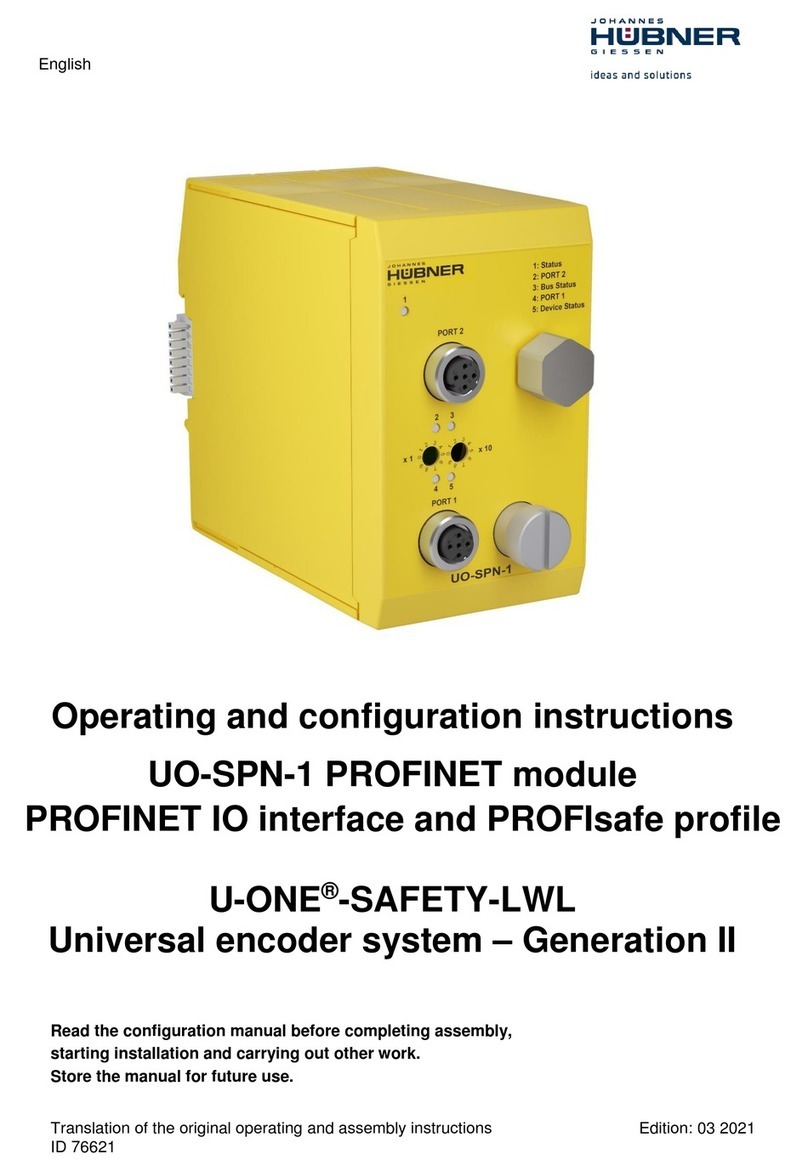
Hubner U-ONE-LWL User manual

English
Translation of the original operating and assembly instructions Edition: 03 2021
ID 76611
Operating and configuration instructions
UO-EPB-1 PROFIBUS module
PROFIBUS-DP interface
U-ONE®-LWL
Universal encoder system –Generation II
Read the operating and assembly manual before assembly, before starting installation and
before completing all other work!
Store the manual for future use.

UO-EPB-1
Operating and configuration instructions
2
UO-EPB1_Manual-en_R1
Manufacturer / author
Johannes Hübner Phone:+49 641 7969 0
Fabrik elektrischer Maschinen GmbH Fax: +49 641 73645
Siemensstr. 7 Website: www.huebner-giessen.com
35394 Giessen / Germany E-Mail: info@huebner-giessen.com
Further current information on this product series is available online in our
Service Point.
Just scan the QR code and open the link in the browser.
These instructions and the enclosed declaration of conformity can also be accessed via our Service
Point. For this purpose, the QR code on the type plate of the corresponding device must be
scanned.
Trademark
Brand and product names are trademarks or registered trademarks of their respective owners.
Protected trademarks ™ or ® are not always designated as such in this manual.
However, this does not mean that they may be used freely.
Copyright protection
This operating and assembly manual, including the figures it contains, are copyright protected. Third
party usage of this operating and assembly manual in deviation from copyright regulations is prohib-
ited. The reproduction, translation or electronic and photographic archiving and amendment of this
manual shall require written approval by the manufacturer. Violations will result in claims for dam-
ages.
Copyright © Johannes Hübner Fabrik elektrischer Maschinen GmbH
Reservation of rights
This operating and assembly manual has been prepared carefully. However, it may contain formal
errors or errors in content.
All rights reserved.

UO-EPB-1
Operating and configuration instructions
UO-EPB1_Manual-en_R1
3
Table of contents
1General information........................................................................................................ 5
1.1 Information on the Operating and configuration manual............................................. 5
1.2 Scope of delivery ....................................................................................................... 5
1.3 Explanation of symbols.............................................................................................. 5
1.4 Warranty and liability.................................................................................................. 6
1.5 Organisational measures ........................................................................................... 6
1.6 Copyright protection................................................................................................... 6
1.7 Warranty provisions ................................................................................................... 6
1.8 Customer service....................................................................................................... 6
2Basic safety information ................................................................................................ 7
2.1 Responsibility of the operator..................................................................................... 7
2.2 Selecting and qualifying personnel; basic obligations................................................. 7
2.3 Proper use................................................................................................................. 7
2.4 Improper use.............................................................................................................. 8
2.5 Safety information...................................................................................................... 8
3Assembly......................................................................................................................... 9
3.1 Safety information...................................................................................................... 9
3.2 Basic regulations........................................................................................................ 9
3.3 Replacing the function module................................................................................... 9
3.4 Type plate................................................................................................................ 10
3.5 Electrical data .......................................................................................................... 10
4Commissioning............................................................................................................. 10
4.1 User manual............................................................................................................. 10
4.2 Profibus profile of the module................................................................................... 11
4.3 Bus addressing........................................................................................................ 12
4.4 Connecting the module to the Profibus..................................................................... 12
4.5 Configure the module............................................................................................... 13
4.6 Configuring the module............................................................................................ 13
4.7 Configuration in hex code......................................................................................... 14
4.8 Operating the module in the Hübner 2.1 and Hübner 2.2 profiles............................. 14
4.9 Desired resolution.................................................................................................... 15
4.9.1 Desired resolution per revolution....................................................................... 15
4.9.2 Desired resolution per maximum total resolution............................................... 15
4.9.3 Desired resolution per physical measurement step ........................................... 16
4.10 Commissioning mode............................................................................................... 16
4.11 Limit switch .............................................................................................................. 16
4.12 Speed output............................................................................................................ 16
5Data transmission modes on the Profibus.................................................................. 17
5.1 Configuring and parameterising the module............................................................. 17
5.1.1 DDLM_Set_Prm mode for Class 1 and Class 2................................................. 17
5.1.2 DDLM_Set_Prm - Modus for Hübner 2.1 and Hübner 2.2.................................. 18
5.2 Commissioning mode............................................................................................... 21

UO-EPB-1
Operating and configuration instructions
4
UO-EPB1_Manual-en_R1
5.2.1 Adopt preset value ............................................................................................ 21
5.2.2 Set counting direction........................................................................................ 22
5.2.3 Scaling the module in the teach in process ....................................................... 22
6Diagnostic messages ................................................................................................... 24
6.1 Operating statuses and displays .............................................................................. 25
6.1.1 Bus status......................................................................................................... 25
6.1.2 Status LED........................................................................................................ 26
7Inspections.................................................................................................................... 26
8Transportation, packaging and storage...................................................................... 26
8.1 Transportation safety information............................................................................. 26
8.2 Incoming goods controlling....................................................................................... 26
8.3 Packaging (disposal)................................................................................................ 26
8.4 Storing packages (devices)...................................................................................... 26
8.5Returning equipment (repair/goodwill/warranty) ...................................................... 27
8.6 Disposal................................................................................................................... 27
9Documents.................................................................................................................... 28
9.1 Dimensional drawing, wiring diagram....................................................................... 28

UO-EPB-1
Operating and configuration instructions
UO-EPB1_Manual-en_R1
5
1 General information
1.1 Information on the Operating and configuration manual
This operating and configuration manual provides important information for using the UO-EPB-1
electronic function module. It must be read carefully before beginning any work and observed.
The UO-EPB-1 electronic function module is referred to in the following documentation as the
EPB.
Furthermore, the local accident prevention regulations and general safety regulations applicable
for the area where the device will be used must be observed.
1.2 Scope of delivery
The operating and configuration manual is included in the scope of delivery for the function mod-
ule.
The scope of delivery for the EPB also includes the software & support CD.
1.3 Explanation of symbols
Warning information is designated using symbols. Information is proceeded by signal words
which express the extent of the danger involved. Always comply with these notices, and use cau-
tion to avoid accidents, personal injury and property damage.
WARNING!
Indicates a potentially hazardous situation that could lead to death or severe injury if it
is not avoided.
CAUTION!
Indicates a potentially hazardous situation that could lead to minor or slight injuries if it
is not avoided.
CAUTION!
Indicates a potentially hazardous situation that could lead to property damage if it is
not avoided.
NOTE!
Emphasises useful tips and recommendations, and provides information useful for effi-
cient, smooth operation.
!

UO-EPB-1
Operating and configuration instructions
6
UO-EPB1_Manual-en_R1
1.4 Warranty and liability
Only the “General Terms and Conditions” of Johannes Hübner Fabrik elektrischer Maschinen
GmbH apply. These will be provided to the operator at the latest when the order is confirmed or
when the contract is concluded. All warranty and liability claims for personal injury and property
damage are excluded, and the operator's operating permit will be null and void if one or more of
the following apply:
Failure to observe the operating and configuration manual.
Improper use of the function module.
Improper assembly, installation, commissioning and programming of the function module.
Operating the function module despite technical defects.
Independently carrying out mechanical or electrical modifications to function modules.
Independently carrying out repairs.
Catastrophes due to external interference or force majeure.
Use of non-qualified personnel.
Opening the function module.
1.5 Organisational measures
The operating and assembly manual must always be stored easily within reach in the area
where the function module is used.
In addition to the operating and configuration manual, general statutory and other binding
regulations on accident prevention and environmental protection must be observed. Opera-
tors must be trained on these regulations.
Applicable national, local, and system-specific provisions and requirements must be ob-
served.
The operator is obligated to inform personnel of special operating considerations and re-
quirements.
The type plate and any prohibitions or notice signs adhered to the function modules must al-
ways be legible.
Repairs may only be carried out by the manufacturer, or by an agency or individual author-
ised by the manufacturer.
1.6 Copyright protection
NOTE!
Content information, texts, drawings, images, and other illustrations are copyright pro-
tected and subject to industrial property rights. Copying of any kind not associated
with use of the function module is prohibited without a written declaration from the
manufacturer. Violations will result in claims for damages.
1.7 Warranty provisions
Warranty provisions are outlined in the manufacturer's General Delivery Conditions.
1.8 Customer service
Contact persons are available by phone, fax, or e-mail for technical questions. See the manufac-
turer’s address on page 2.

UO-EPB-1
Operating and configuration instructions
UO-EPB1_Manual-en_R1
7
2 Basic safety information
DANGER!
This section provides an overview of all significant safety aspects necessary to pro-
tect personnel and ensure safe, fault-free operation of the function module. Failure
to observe this information may result in significant danger.
2.1 Responsibility of the operator
The function module is used in commercial areas. The operator of the function modules, there-
fore, is subject to statutory occupational safety requirements and the safety, accident prevention
and environmental regulations applicable to the areas in which the function modules are used.
2.2 Selecting and qualifying personnel; basic obligations
All work on the function module may be carried out only by qualified personnel. Qualified per-
sonnel are personnel with the training, experience, and instruction, as well as expertise on
relevant standards, specifications, accident prevention regulations and operating circum-
stances necessary to carry out the required work, and who have been authorised to do so by
the persons responsible for the safety of the system. They are able to identify and avoid po-
tential hazards.
In addition, please see standards VDE 0105-100 and IEC 364 for the definition of “qualified
personnel” (reference, e.g. Beuth Verlag GmbH, VDE-Verlag GmbH)
Responsibilities for assembly, installation, commissioning and operation must be clearly de-
fined. Personnel who are receiving instruction or training must be supervised.
2.3 Proper use
The system manufacturer must review whether the properties of the function module fulfil the
safety requirements in its specific application. The system manufacturer is responsible for use of
the function module and for deciding whether to use the module. Function modules are designed
for unsupervised, continuous operation.
Proper use also includes:
observing all information in this operating and configuration manual
observing type plates and any prohibition or information signs
observing the operating manual of the machine or system manufacturer.
operating the function module within the limits stipulated in the technical data
not engaging in improper use.

UO-EPB-1
Operating and configuration instructions
8
UO-EPB1_Manual-en_R1
2.4 Improper use
WARNING!
Danger of death, physical injury and property damage due to improper use of the
function module!
In particular, the following uses are prohibited:
●Use in environments with an explosive atmosphere.
●Use in environments with radioactive radiation.
●Use on ships.
●Use for medical purposes.
2.5 Safety information
WARNING! ATTENTION! NOTE!
Destruction, damage or impact to the function of the function module.
●Only complete wiring work and only connect or disconnect electrical
connections when the module is powered down.
●Review any potential hazards due to interactions with other systems and
devices currently installed in the surrounding area, or which are to be installed.
The user is responsible for taking relevant measures.
●Cables used must be suitable for the temperature range.
●Defective function modules may not be operated.
●Opening function modules is prohibited.
●The type plates specify the technical properties of the function modules. If a
type plate is no longer legible, or if a type plate is missing entirely, the function
module may not be operated. Contact Hübner service (see page 2).
NOTE!
Disposal:
If the function module needs to be disposed after its service life, applicable national
regulations must be observed.
!

UO-EPB-1
Operating and configuration instructions
UO-EPB1_Manual-en_R1
9
3 Assembly
3.1 Safety information
WARNING!
●Assembly and disassembly may only be carried out by qualified personnel.
Observe the safety information in section 2.
●In general, the requirements and acceptance conditions for the system as a
whole must be observed.
DANGER! ATTENTION!
Danger of death, severe physical injury and/or property damage due to
deactivating safety functions, caused by an unsecured shaft drive.
●In general, the requirements and acceptance conditions for the system as a
whole must be observed.
3.2 Basic regulations
WARNING!
●Power and signal lines must be installed separately.
●Observe the manufacturer’s information when installing converters, shielding on
power lines between the frequency converter and motor.
●Ensure the energy supply is sufficient for the application.
3.3 Replacing the function module
When replacing function modules, observe the following:
The new function module must have the same item no. (ID) as the old one.
When recommissioning the replaced function module, a secure test run must be completed
first to ensure it functions correctly.

UO-EPB-1
Operating and configuration instructions
10
UO-EPB1_Manual-en_R1
3.4 Type plate
The following image shows an example of a type plate.
The type plate is located on the outside
of the housing, and includes the following
information:
Manufacturer
Type, year of construction
CE mark
Serial number (S/N)
Protective class
ID number
Certification information
3.5 Electrical data
Information
Value
Supply voltage
Delivered to the SCU module via the module bus connector
Device temperature range
-25°C…+ 60°C
Power consumption
< 3 W
Connection technology
Sub-D
Protective class in accord-
ance with DIN EN 60529
IP20 for cabinet installation
Degree of protection of cabinet: ≥ IP54
Elevation above sea level
≤ 3000 m
4 Commissioning
4.1 User manual
The module transmits the Multiturn and Singleturn absolute value for the basic device. It can be
configured in profiles CLASS 1 (Hübner 1.0) with configuration of the counting direction and
CLASS 2 (Hübner 2.0) with the additional setting for resolution / revolution and the overall resolu-
tion.
The profiles Hübner 2.1 and Hübner 2.2 are also available. These also provide the following func-
tions:
Expanded scaling function
Setting the counting direction, preset and automatic scaling (teach in) during online operation
in commissioning mode.
Limit switch function
Speed output
This function outsources part of the computing power from the Profibus® master to the function
module and relieves the load placed on the overall system. If these additional functions are not
required, however, then to simplify configuration it may make sense to use CLASS 1 or CLASS2
profiles.
Fig. 3-1: Type plate (example)

UO-EPB-1
Operating and configuration instructions
UO-EPB1_Manual-en_R1
11
4.2 Profibus profile of the module
The module behaves like a Multiturn encoder designed for operation on the Profibus®. It can be
configured and parameterised as either a Multiturn or Singleturn module in the following profiles:
Encoder profile
Configuration options
HÜBNER 1.0 Single / Multiturn
(CLASS 1)
Counting direction
HÜBNER 2.0 Single / Multiturn
(CLASS 2)
Counting direction
Switch the HÜBNER 2.0 function on/off
Switch the scaling function on/off
Resolution / rotation
Total resolution
HÜBNER 2.1 Single / Multiturn
Like HÜBNER 2.0, in addition:
Desired measurement steps
Desired resolution per
- revolution
- maximum total resolution
- physical measurement steps
Switching the commissioning module on/off
Set preset value and change counting direction in online
mode
Determine gear factor (scale)
Switch lower limit switch on/off
Lower limit switch (position)
Switch upper limit switch on/off
Upper limit switch (position)
HÜBNER 2:2 Single / Multiturn
Like HÜBNER 2.1, in addition
speed output
NOTE!
The module can be operated in HÜBNER 1.0, HÜBNER 2.0, HÜBNER 2.1 and
HÜBNER 2.2 independent of whether CLASS 1 or CLASS 2 was selected.

UO-EPB-1
Operating and configuration instructions
12
UO-EPB1_Manual-en_R1
4.3 Bus addressing
The addressing switch can be used to define the bus address:
x 10 = tens digit
x 1 = ones digit
4.4 Connecting the module to the Profibus
After installing the module and connecting it to the power supply, connect the module to the Profi-
bus system. This example describes the process using the COM PROFIBUS V 5.0 installation
software and the PROFIBUS-DP master IM308C.
First, copy the manufacturer-specific bitmap files (.bmp, .dib) into the BITMAPS directory and
copy the GSD file into the GSD directory of the COM PROFIBUS software. Then start the COM
PROFIBUS installation software. Create a new configuration file using the NEW menu item under
the FILE menu, or access a configuration file via the OPEN menu item. Then read in the GSD file
in the menu item READ IN GSD FILES.
Now, search for type IM308C under the DP master and search for HÜBNER encoder AMP1212
under DP slave / encoder, then double click to integrate these into the bus graphic in the right
window.
Use the menu PLAN / PLAN DP SLAVE or right click on the encoder symbol and PROPERTIES
to access the SLAVE PROPERTIES window. Enter the module bus address matching the pre-
selector switches on the module. Then continue using the CONFIGURE menu item.
Encoder
Master

UO-EPB-1
Operating and configuration instructions
UO-EPB1_Manual-en_R1
13
4.5 Configure the module
Now, select the profile in which the module should work. Then assign the input and output ad-
dresses and complete configuration. This function can be accessed in the Configure window us-
ing the Parameter button, and offers a simple, easy to understand way to set the parameters.
Configurations must be set in other windows in hexadecimal form, in contrast, and require a pre-
cise understanding of the meaning of the individual bits and bytes.
4.6 Configuring the module
In this example, the Configure window shows the setting options for an absolute encoder config-
ured as HÜBNER 2.0.
NOTE!
If the class 2 function is switched off, then the module will work in HÜBNER 1.0
mode. In this case, only the counting direction can be changed.
The resolution per revolution can be any value between 1 and 4096 and deter-
mines the step length.
The total resolution indicates the number of revolutions the measurement by the
basic device using the selected resolution per revolution lasts until the position
zero is read out again.
Total resolution = resolution per revolution x number of revolutions. The number
of revolutions must be equal to 2nwith a value between 0 and 12 for n.

UO-EPB-1
Operating and configuration instructions
14
UO-EPB1_Manual-en_R1
If this is not observed, the module will detect a configuration error. This will be displayed in the
junction box cover. The red LED will be continuously illuminated, and the green one will flash.
NOTE!
To activate configuration of resolution per revolution, the class 2 function and the
scaling function must be switched on. The preset should then be reset in normal op-
eration, since it refers to the scaled values.
4.7 Configuration in hex code
The configuration can also be carried out in the HEX –CONFIGURE window. However, this is
time consuming and requires a precise knowledge of the functions of the individual bits and
bytes.
4.8 Operating the module in the Hübner 2.1 and Hübner 2.2 profiles
These two profiles have some additional functions in addition to the standard profiles, the config-
uration of which is explained here based on COM Profibus®.
The scaling function must be switched on to operate the additional functions.
Octet

UO-EPB-1
Operating and configuration instructions
UO-EPB1_Manual-en_R1
15
4.9 Desired resolution
In contrast to the profile Hübner 2.0 (CLASS 2), there are three different scaling options to
choose from here:
Desired resolution per:
revolution
Maximum total resolution
Physical measurement steps
4.9.1 Desired resolution per revolution
Here, the user can set the number of steps the basic device should output during a revolution.
In addition, the length of the total possible measurement path and therefore the number of revolu-
tions are entered into the fields for the overall resolution.
Example:
8 steps / revolution are desired. The total measurement range should be completed after 8 revo-
lutions, and should start over again. A total of
8 x 8 = 64
steps are required for this purpose. 8 steps should then be entered in the desired measurement
step, and 64 steps in total resolution.
NOTE!
The number of revolutions must have a value of 2nwith (n = 1 ..12).
Failure to observe these requirements will cause the output position values to be am-
biguous, since the transition from the maximum basic device position to the position
value of 0 will then always be completed at different basic device settings.
4.9.2 Desired resolution per maximum total resolution
In this type of scaling, the maximum possible measurement range for the basic device is divided
into a defined number of steps. This number must be entered into the fields for DESIRED MEAS-
UREMENT STEPS.
Example:
The total measurement range for the module should be divided into 16384 steps.
16384 : 4096 = 4 steps per revolution
The number of desired measurement steps must be less than the maximum total resolution.
This type of scaling is also used in commissioning mode with automatic scaling (teach in).

UO-EPB-1
Operating and configuration instructions
16
UO-EPB1_Manual-en_R1
4.9.3 Desired resolution per physical measurement step
This setting always refers to dividing the code disc into 4096 measurement steps. The number
indicating how many parts the value entered under physical measurement step was divided into
must be entered in the input field for the desired measurement step.
Example:
Physical measurement steps =2048, desired measurement steps = 64.
2048 : 64 =32
Therefore, a desired measurement step is 32 physical measurement steps long.
NOTE!
This value must be contained in the total resolution 2n.
Failure to observe these requirements will cause the output position values to be am-
biguous, since the transition from the maximum basic device position to the position
value of 0 will then always be completed at different basic device settings.
4.10 Commissioning mode
If this mode is activated, the following functions are available in online mode:
Changing the counting direction
Setting the preset value
Automatic scaling (teach in)
These values are set by the Profibus® master by manipulating the status bit in DDLM_DATA_EX-
CHANGE mode. A more detailed description is provided in a later section.
4.11 Limit switch
There are two software limit switches available that can be activated using the fields lower limit
switch and upper limit switch. The desired positions of the switches refer to the selected total res-
olution, and may not exceed this total resolution. They must be entered into the fields Lower limit
switch (HIGH/LOW) and Upper limit switch (HIGH/LOW).
For positions between the two switch positions, the relevant status bit (Bit 27) is set to LOW. Ex-
ceeding or falling below the specified relevant position will set the bit to HIGH.
4.12 Speed output
This function is only available with encoder profile HÜBNER 2.2. The following output options are
available:
Steps /1000 ms
Steps /100 ms
Steps /10 ms
Revolutions / min

UO-EPB-1
Operating and configuration instructions
UO-EPB1_Manual-en_R1
17
5 Data transmission modes on the Profibus
Three data transmission modes are required to operate the module on the Profibus®:
The data required for configuration and parameterisation is transmitted by the master to the
module connected to the slave when the system is started up in DDLM_Set_Prm mode. 16 –
39 Bytes (Octets) are required for this purpose, depending on the encoder profile.
The master requests module output data in DDLM_Data_Exchange mode. Some parameters
can be changed in online mode with a configuration as Hübner 2.1 or Hübner 2.2.
The master requests diagnostic data from the module in DDLM_Slave_Diag mode.
Normally, configuration and parameterisation are carried out automatically in DDLM_Set_Prm
mode when starting up the system and during continued operation in DDLM_Data_Exchange
mode.
Settings for the required functions are set first via selection menus in Profibus system windows
(COMProfibus).
In some cases, however, it is necessary to know the commands used for this purpose in order to
change parameters manually.
5.1 Configuring and parameterising the module
The following section describes which bits can be set in DDLM_SET_PRM mode. Octets 1-8 con-
tain Profibus®-specific data and should not be changed.
5.1.1 DDLM_Set_Prm mode for Class 1 and Class 2
Octet
Parameter
Bit no.
9
Counting direction
0
Right = 0, left = 1
Class 2 function
1
Off = 0, on = 1
Commissioning Diagnos-
tics
2
Not used for AMP 1212
Scaling function
3
Off = 0, on = 1
Reserved
4
---
Reserved
5
---
Optional for Hübner 2.1
and 2.2
6
Not for Class 1 and Class 2
Reserved
7
10 - 13
Resolution per revolution
231 –20
max. 4096
14 - 17
Overall resolution
231 –20
max. 4096 x 4096
Only the counting direction bit can be changed in Class 1 mode.
5.1.1.1 Class 2 function (Octet 9.1)
This bit can be set to 0 to switch into Class1 operation.

UO-EPB-1
Operating and configuration instructions
18
UO-EPB1_Manual-en_R1
5.1.1.2 Scaling function (Octet 9.3)
If this bit is turned off, the module will have a resolution per revolution of 4096 steps and a total
resolution of 4096 x 4096 steps. (corresponds to 4096 revolutions. Bit 3 = 1) can be used to scale
the resolution per revolution and the total resolution.
5.1.1.3 Resolution per revolution (Octet10 –13)
This value may not exceed 4096, so that the output code does not become ambiguous
5.1.1.4 Total resolution (Octet14 –17)
A multiple of the resolution / revolution must be entered here, whereby the multiple represents the
number of revolutions and may only have a value of 2n(with 1 < n < 12).
NOTE!
Total resolution = resolution per revolution x number of revolutions (2n)
If other values are used for the number of revolutions, then there will be jumps when transitioning
from the maximum position to the position 0, and the position data will no longer be unambigu-
ous.
5.1.2 DDLM_Set_Prm - Modus for Hübner 2.1 and Hübner 2.2
The user profiles HÜBNER 2.1 and HÜBNER 2.2 are a supplement to the CLASS 2 profile. They
offer additional functions the user can take advantage of. Unused functions can be switched off.
Online configuration in DDLM_DATA_EXCHANGE mode is possible to set the counting direction,
the preset and the gear factor.
In addition, speed output is available with the HÜBNER 2.2 profile.
Bits and bytes when configuring Hübner 2.1 and Hübner 2.2
Octet
Parameter
Bit no.
9
Counting direction
0
Right = 0, left = 1
Class 2 function
1
Off = 0, on = 1
Commissioning Diagnostics
2
---
Scaling function
3
Off = 0, on = 1
Reserved
4
---
Reserved
5
---
Hübner 2.1 and 2.2
6
Off = 0, on = 1
Reserved
7
10 –13
Measurement steps per xxx
231 –20
s. Oct. 26/Bit 1 + 0
14 –17
Overall resolution
18 - 25
Reserved for encoder profile
26
Desired measurement steps
1 + 0
00H per revolution
01H per max. total resolution
10H physical measurement steps
Commissioning mode
2
Off = 0, on = 1

UO-EPB-1
Operating and configuration instructions
UO-EPB1_Manual-en_R1
19
Octet
Parameter
Bit no.
Reduced diagnostics
3
Off = 0, on = 1
Reserved
4
---
Software limit switch min.
active
5
Off = 0, on = 1
Software limit switch max.
active
6
Off = 0, on = 1
Octet 27 –39 active
7
Off = 0, on = 1
27 - 30
Limit switch min.
231 –20
31 - 34
Limit switch max.
231 –20
35 - 38
Physical measurement
steps
231 –20
39
Reserved
0
---
Singleturn/Multiturn
1
Singleturn = 0, Multiturn = 1
Reserved
2
---
Reserved
3
---
Speed unit
5 + 4
00H steps/s
01H steps/100ms
10H steps/10ms
11H RPM
Reserved
6
---
Reserved
7
---
5.1.2.1 Hübner 2.1 and 2.2 (Octet 9.6)
This bit is used to release other module functions available in this profile (in Octet 26).
5.1.2.2 Measurement steps per xxx (Octet 10–13) + desired measurement steps (Octet 26.0,
26.1)
The bits for the desired measurement steps (Octet 26.0 and 26.1) can be used to save a value in
Octet 10...13 that refers to the following ranges:
Measurement steps per revolution
Measurement steps per max. total resolution
Physical measurement steps
Regarding measurement steps per revolution (Octet 26.0 and 26.1, 00H)
This input is based on one revolution of the basic device, and indicates how many steps it is
divided into. Values up to 4096 can be set. The measurement range of the module is defined
in conjunction with the total resolution of the basic device, which is stored in Octet 14 –17.
(See total resolution)

UO-EPB-1
Operating and configuration instructions
20
UO-EPB1_Manual-en_R1
Regarding measurement steps per max. total resolution (Octet 26.0 and 26.1, 01H)
This indicates the number of measurement steps based on 4096 revolutions, and refers to
the entire measurement range for the module.
Regarding physical measurement steps (Octet 26.0 and 26.1, 10H)
The resolution is equal to that of the code disc with 4096 steps. The number of revolutions 2n
(1 < n < 12 see total resolution) is dependent on the value for total resolution. The set meas-
urement range can be scaled in this mode.
To do so, enter the number of steps into which the range for total resolution should be di-
vided in Octets 35 to 39. Apart from direct input, scaling can also be determined via a teach-
in process.
5.1.2.3 Commissioning mode (Octet 26.2)
This switch is used to set a special status in DDLM_Set_Prm mode in which the preset value and
other parameters are transmitted to the module when the system is ready for operation and
stored there in a failsafe memory. A gear factor can also be determined in this mode. These de-
termined parameters should be noted, and then transmitted to the module when the bus is re-
started in DDLM_Set_Para mode, and commissioning mode should be switched off.
5.1.2.4 Reduced diagnostics (Octet 26.4)
Some Profibus masters, generally older ones, cannot receive all diagnostic bytes of the module.
(See the documentation for the master used). When the bit is set, only 16 diagnostic bits are
transferred.
5.1.2.5 Octet 27 –39 active (Octet 26.7)
If this bit is set, it provides access to Octets 27 –39. This releases the functions limit switch min.
and max., scaling via physical measurement steps, Singleturn / Multiturn, and speed units (only
HÜBNER 2.2).
5.1.2.6 Software limit switch min. and max. (Octet 26.5 and 26.6) and (Octets 27 –34)
If this bit is set, the software limit switches min. (Octet 26.5) and max. (Octet 26.6) are activated.
The position values required for this purpose are stored for limit switch min. in Octets 27 –30 and
for limit switch max. in Octets 31 –34. This function is only available when programming class
HÜBNER 2.1 and 2.2.
5.1.2.7 Physical measurement steps (Octet 35 –38)
The number of physical measurement steps is saved in these Octets. It divides the value of total
resolution, and therefore serves to scale the module.
5.1.2.8 Singleturn / Multiturn (Octet 39.1)
This bit is normally set by selecting the class of the module and can be used to determine the
type of coder.
5.1.2.9 Speed unit (Octet 39, 5+4)
The speed can be output when class Hübner 2.2 is selected. Bits 5 and 4 of Octet 39 can be
used to set the following output types:
00H steps / s
01H steps / 100 ms
This manual suits for next models
2
Table of contents
Other Hubner Control Unit manuals
Popular Control Unit manuals by other brands

KLINGER SCHÖNEBERG
KLINGER SCHÖNEBERG Chemoball KH2F-CI Assembly and Repair Instructions

Eaton
Eaton Vickers SF4-140-20-002-10 Overhaul manual

Notifier
Notifier TM-4 Product installation document

Magnetic
Magnetic MGCplus manual

Omron
Omron SYSMAC LINK C1000H-SLK21-V1 System manual

ProSoft Technology
ProSoft Technology ControlLogix inRAx MVI56E-MNETR user manual