HubWayLD8Di / HubWayLD16Di - 3 -
Installation Instructions:
1. Set the input voltage selector switch located on the left side of the HubWayLD8Di/LD16Di unit (facing
front panel) for 115VAC or 230VAC operation (Fig. 1k, pg. 4).
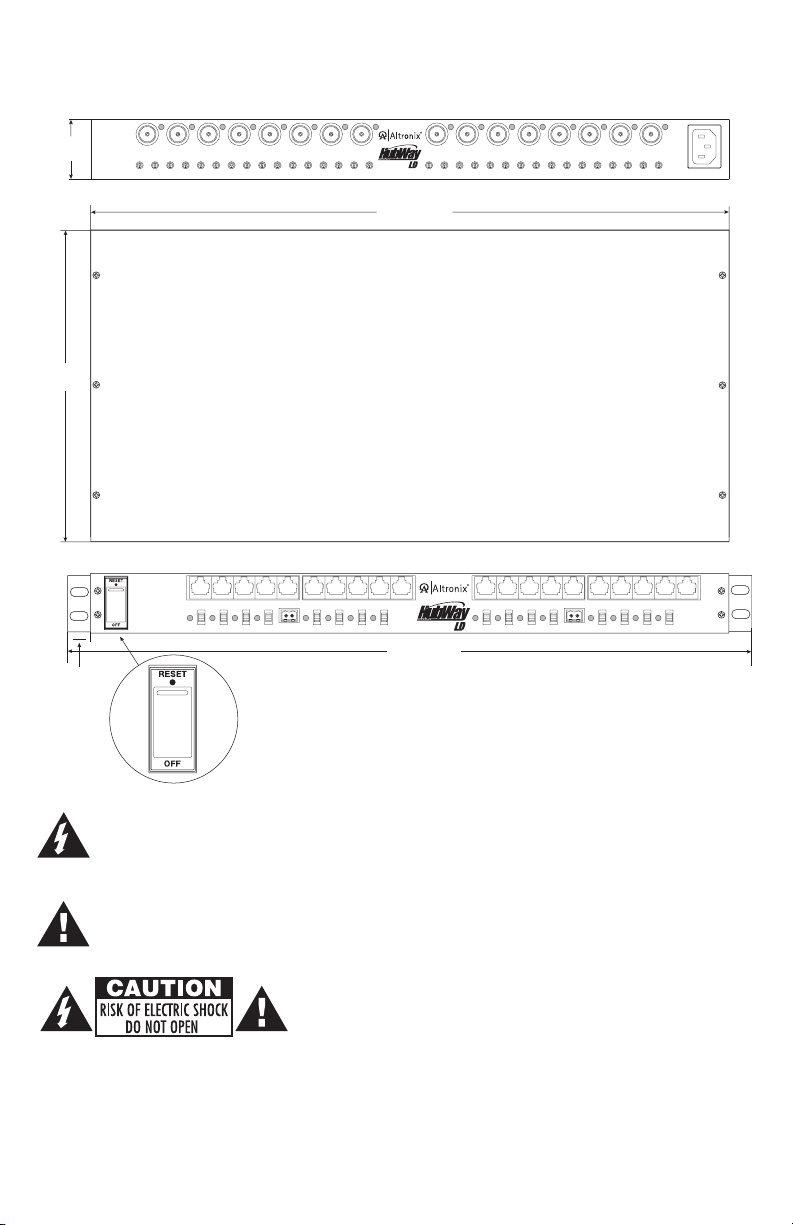
2. Attach mounting brackets to HubWayLDi unit for rack or wall mount installation (Figs. 6-7, pg. 8). Affix
rubber pads to HubWayLDi for shelf installation (Fig. 8, pg. 8).
3. Secure the unit in a rack, mount unit to a wall or place unit on a shelf as desired (unit should be spaced at
least 3” from any video monitors).
4. Set illuminated master power disconnect circuit breaker to the (OFF) position (Fig. 5, pg. 7).
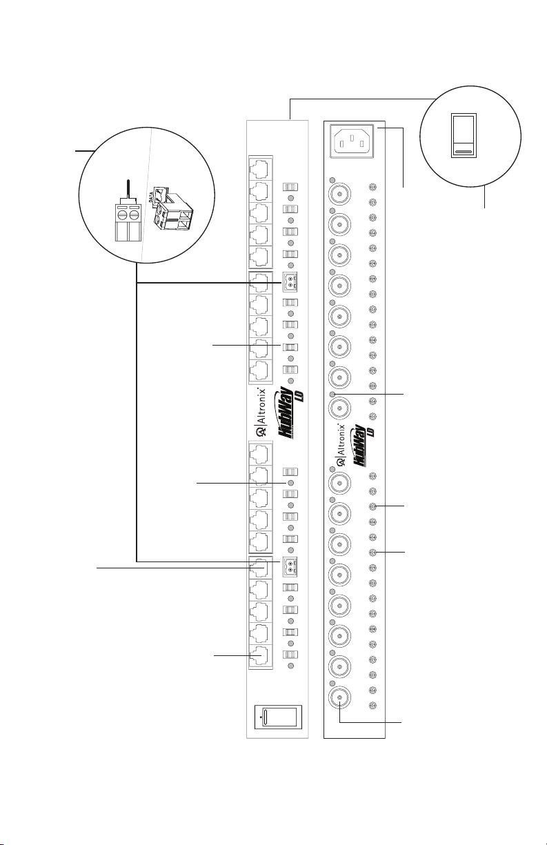
5. Plug the grounded AC line cord (included) into the IEC 320 connector of the HubWayLD8Di/HubWayLD16Di
unit (Fig. 1j, pg. 4). Insert the plug end of the line cord into a grounded AC receptacle.
6. Set voltage output selector switch of each camera channel for 24VAC or 28VAC (Fig. 1d, pg. 4).
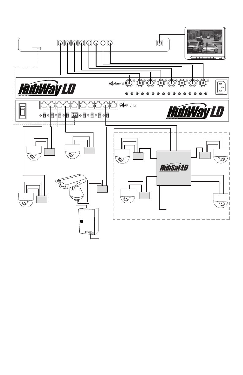
7. Connect the BNC video outputs for HubWayLD8Di/LD16Di Channels 1 - 8 (Channels 1-16) to the
corresponding video inputs on the head end equipment (DVR) (Fig. 1f, pg. 4).
8. Connect the RS422/RS485 output of the head end equipment (DVR) to the one (1) or both data input terminal
blocks of the HubWayLD8Di or HubWayLD16Di unit (polarity must be observed) (Fig. 1e, pg. 4).
Note: The Data input terminals of the HubWayLD8Di or HubWayLD16Di must be wired in parallel for
proper operation. When using fixed cameras disregard this step.
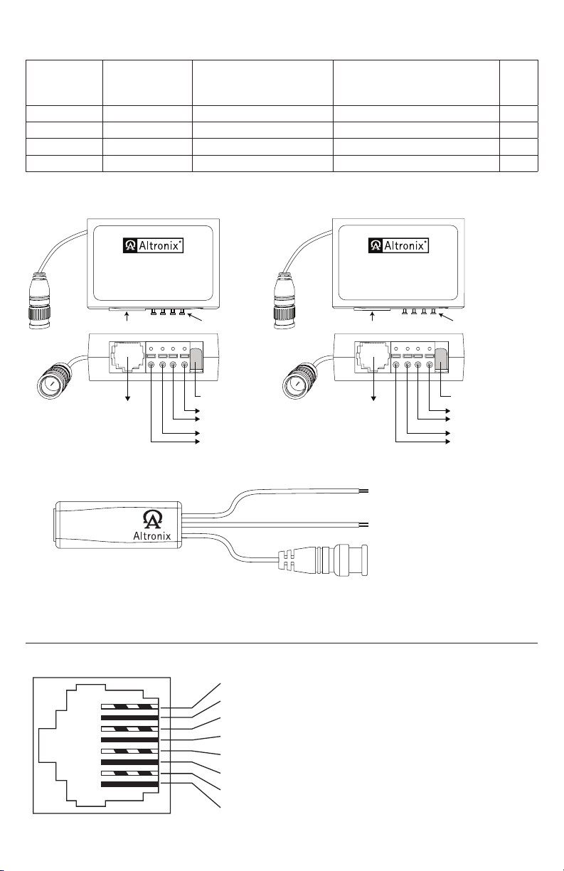
9. Connect Video Balun/Combiner at camera 1 to the HubWayLD8Di or HubWayLD16Di unit utilizing
CAT-5 or higher structured cable. Plug the RJ45 connector at one end of the structured cable into the RJ45
jack marked [Channel 1] of the HubWayLD8Di/LD16Di (Fig. 1a, pg. 4). Plug the RJ45 connector at the
opposite end of the structured cable into the RJ45 jack of the Video Balun/Combiner located at camera 1.
• For 24VAC cameras use Altronix model HubWayAv/HubWayAv2 Video Balun/Combiner
(Figs. 2a, 2b, 2e, pg. 5).
• For 12VDC cameras use Altronix model HubWayDv Video Balun/Combiner (Figs. 2c, 2d, pg. 5).
• For non-isolated 12VDC cameras use Altronix model HubWayDvi Video Balun/Combiner
(Figs. 2c, 2d, pg. 5).
Repeat steps 6-9 for each additional camera (Channels 2-8 or Channels 2-16).
Note: When a particular camera exceeds the maximum distance for power transmission, a local external power
source is required. Optionally, an Altronix HubSat4D Passive UTP Transceiver Hub with Integral Camera
Power may be utilized (Fig. 4a, pg. 6).
The combined total cable distance must not exceed 3000 ft. for video transmission between the
HubWayLD8Di/LD16Di and each camera routed through the HubSat4D.
10. Set illuminated master power disconnect circuit breaker to the RESET (ON) position (Fig. 5, pg. 7) and
measure the output voltage at the power output of each Video Balun/Combiner (Figs. 2b, 2d, pg. 5) before
powering each camera to ensure proper operation and avoid possible damage.
• HubWayAv/HubWayAv2 - Terminals marked [AC POWER] (Figs. 2a, 2b, 2e, pg. 5).
• HubWayDv/HubWayDvi - Terminals marked [– 12VDC +] (Figs. 2c, 2d, pg. 5).
11. Set illuminated master power disconnect circuit breaker to the (OFF) position to make the final connections
(Fig. 5, pg. 7).
12. Connect the power outputs of the HubWayAv, HubWayAv2, HubWayDv or HubWayDvi Video Balun/
Combiners to the power inputs of the cameras (Figs. 2a-2e, pg. 5). Polarity must be observed.
13. Connect the terminals marked [+ DATA –] of the HubWayAv or HubWayDv Video Balun/Combiners to
the data terminals of the cameras for PTZ control (Figs. 2a-2e, pg. 5). Polarity must be observed.
When using fixed cameras disregard this step.
14. Connect the BNC connector of the HubWayAv, HubWayAv2, HubWayDv or HubWayDvi Video Balun/
Combiners to the BNC video outputs of the cameras (Figs. 2a-2e, pg. 5).
15. Upon completion of wiring set illuminated master power disconnect circuit breaker to the RESET (ON)
position (Fig. 5, pg. 7).
16. The power LEDs (Red) located on the front of the HubWayLD8Di/LD16Di will illuminate when AC
power is present (Fig. 1c, pg. 4).
Note: If any of these LEDs are not illuminated, either a voltage output selector switch is in the OFF position
or the PTC is tripped for that channel.
To reset the PTC:
1. Set the voltage output selector switch for that corresponding channel to the OFF position.
Switch must remain in the OFF position for approximately 2 minutes in order for the PTC to reset.
2. Eliminate the trouble condition (short circuit or overload).
3. Set the voltage output selector switch for 24VAC or 28VAC (Fig. 1d, pg. 4).
17. AC LED (Green) of the HubWayAv or DC LED (Red) of the HubWayDv/HubWayDvi Video Balun/
Combiners will illuminate indicating power is present at the cameras (Fig. 2b, 2d, pg. 5).
18. The video signal indicator LEDs (Red) located on the rear of the HubWayLD8Di /LD16Di will illuminate
when video signal is present (Fig. 1i, pg. 4). If any of these LEDs are not illuminated, no video signal is
present for that corresponding channel.
19. Optimize the picture quality for Channels 1-8 (Channels 1-16) by adjusting the corresponding
potentiometers marked [Picture] (Fig. 1g, pg. 4).
20. Set gain for Channels 1-8 or Channels 1-16 by adjusting the corresponding potentiometers marked [Gain]
(Fig. 1h, pg. 4).