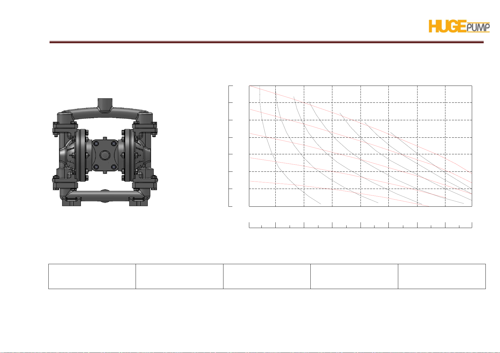
HP 05 PUMP USER’S MANUAL
Page8
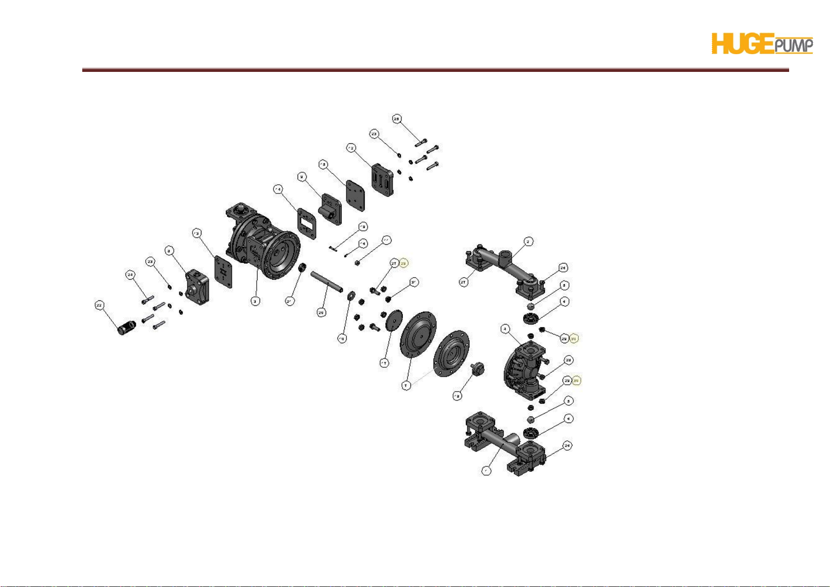
METALLIC PUMP COMPOSITE PARTS LIST
1S010530 Suction Line 1
2S020530 Discharge Line 1
3H010533 Main Body 1
4S030530 Outer Chamber 2
5S040545 Check Ball 4
S040546 Check Ball 4
S040547 Check Ball 4
S040548 Check Ball 4
S040550 Check Ball 4
S040551 Check Ball 4
6S050536 Check Ball Seat 4
S050545 Check Ball Seat 4
S050546 Check Ball Seat 4
S050547 Check Ball Seat 4
S050548 Check Ball Seat 4
S050550 Check Ball Seat 4
S050551 Check Ball Seat 4
7S060545 Diaphragm 2
S060546 Diaphragm 2
S060547 Diaphragm 2
S060548 Diaphragm 2
S060550 Diaphragm 2
S060551 Diaphragm 2
8H030533 Air Valve Repair Kit 1
9H040533 Pilot Valve Repair Kit 1
10 H050547 Bumper 2
11 H060536 Pin Bushing 2
12 H070533 Cover, Air Inlet Assembly 1
13 H080547 Gasket, Air Valve 1
14 H090547 Gasket, Pilot Valve, Front 1
15 H100547 Gasket, Pilot Valve, Rear 1
16 H120547 O-ring, Pin 2
17 H130590 Inner Diaphragm Holder 2
18 S070533 OuterDiaphragm Holder 2
19 H140590 Actuator Pin 2
20 H150590 Diaphragm Rod 1
21 H160545 Oil Seal 2
22 H170536 Muffler 1
23 PM6-P Washer, M6 8
PM6 Washer, M6 8
24 CM6X30-Pİ Capscrew M 6 X 30 (imbus)4
CM6X30-İCapscrewM 6 X 30 (imbus)4
25 CM6X35-P CapscrewM 6 X 35 4
CM6X35-İCapscrewM 6 X 35 4
26 CM8X35-P CapscrewM 8 X 35 8
CM8X35 CapscrewM 8 X 35 8
27 CM8X25-P CapscrewM 8 X 25 12
CM8X25 CapscrewM 8 X 25 12
28 CM8X40-P Capscrew M 8 X 40 12
CM8X40 Capscrew M 8 X 40 12
29 PM8-P Washer, M8 8
PM8 Washer, M8 8
30 SM8-PRing Nut, M8 8
SM8 Ring Nut, M8 8
31 SM8-PF Ring Nut, M8, Flanged 12
SM8-F Ring Nut, M8, Flanged 12