Huge Pump HP 10 User manual

HP 10 PUMP USER’S MANUAL
Page 1
USER MANUAL
HP 10 PLASTIC/ METAL PUMPS

HP 10 PUMP USER’S MANUAL
Page 2
HP 10 PUMPS DEVIDED INTO TWO CATEGORIES WHICH ARE:
METALLIC PUMPS PLASTIC PUMPS

HP 10 PUMP USER’S MANUAL
Page 3
COMPRESSED AIR DOUBLE DIAPHRAGM
TRANSFER PUMPS
TABLE OF CONTENT
METALLIC PUMP’S PERFORMANCE CURVES 4
METALLIC PUMP’S DIMENSIONS 5
METALLIC PUMP’S PACKAGING 6
METALLIC PUMP’S SPARE PARTS DRAWINGS 7
METALLIC PUMP’S SPARE PARTS LIST 8
PLASTIC PUMP’S PERFORMANCE CURVES 10
PLASTIC PUMP’S DIMENSIONS 11
PLASTIC PUMP’S PACKAGING 12
PLASTIC PUMP’S SPARE PARTS DRAWINGS 13
PLASTIC PUMP’S SPARE PARTS LIST 14
DIAPHRAGM MATERIALS 16
PRINCIPLE OF PUMP OPERATİON 17
INSTALLATION &START UP 17
AREAS OF APPLICATION 19
AIR CONNECTION 21
AIR VALVE LUBRICATION 21
AIR LINE MOISTURE 21
AIR INLET AND PRIMING 21
FREQUENCY OF USE 22
TROUBLESHOOTING 22
WARNINGS 23
PUMPING HAZARDOUS LIQUIDS 25
AIR VALVE ASSEMBLY 26
AIR VALVE MAINTENANCE 27
PILOT VALVE ASSEMBLY 28
PILOT VALVE MAINTENANCE 29
DIAPHRAGM MAINTENANCE 30
INTERMEDIATE ASSEMBLY MAINTENANCE 32
METALLIC CHECK VALVE MAINTENANCE 33
PLASTIC CHECK VALVE MAINTENANCE 34
ADRESS 35

HP 10 PUMP USER’S MANUAL
Page 4
0
1
2
3
4
5
6
7
020 40 60 80 100 160
140120
4,1 bar
5,5 bar
2,8 bar
1,4 bar
Basma Yüksekliği
( bar) 10 m3/h (hava giriş debisi)
6,7 bar (hava giriş basıncı)
Dakikadaki Litre Kapasitesi ( lt/dk)
67 m3/h
50 m3/h
40 m3/h
35 m3/h
20 m3/h
16 m3/h
HP 10 (1”) METALLIC PUMP PERFORMANCE CURVES
HP 10 (1”) METALLIC PUMP
The operation pressure is 0 to 7 bars.
Operation temperature is between (-18 ˚Cand 100 ˚C.)
Suction / Discharge 1"
Max. Capacity 150 lpm
Max. Solid particle
permeability (4 mm)
Max. Operation pressure
7 bar
Weight 9 kg (Aluminum)
Volumetric Capacity - LPM
Pump Head

HP 10 PUMP USER’S MANUAL
Page 5
METRIC DIMENSIONS [ mm ]
Dimensional tolerances ± 3 mm
A
B
C
D
E
F
G
H
I
J
K
273
166
216
348
179
169
298
112
130
315
200

HP 10 PUMP USER’S MANUAL
Page 6
PACKING DIMENSIONS[ mm ]
A
B
C
390
350
550

HP 10 PUMP USER’S MANUAL
Page 7
COMPOSİTE PARTS DRAWING OF HP 10 (1”) METALLIC PUMP

HP 10 PUMP USER’S MANUAL
Page8
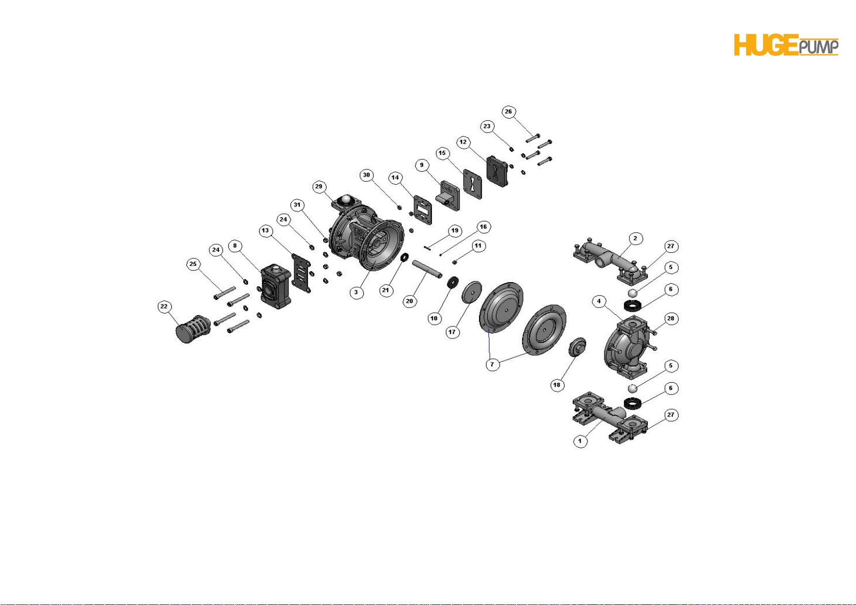
METALLIC PUMP COMPOSITE PARTS LIST
1S011030 Suction Line 1
S011031 Suction Line 1
S011032 Suction Line 1
2S021030 Discharge Line 1
S021031 Discharge Line 1
S021032 Discharge Line 1
3H011033 Main Body 1
4S031030 Outer Chamber 2
S031031 Outer Chamber 2
S031032 Outer Chamber 2
5S041045 Check Ball 4
S041046 Check Ball 4
S041047 Check Ball 4
S041048 Check Ball 4
S041050 Check Ball 4
S041051 Check Ball 4
6S051036 Check Ball Seat 4
S051045 Check Ball Seat 4
S051046 Check Ball Seat 4
S051047 Check Ball Seat 4
S051048 Check Ball Seat 4
S051050 Check Ball Seat 4
S051051 Check Ball Seat 4
7S061045 Diaphragm 2
S061046 Diaphragm 2
S061047 Diaphragm 2
S061048 Diaphragm 2
S061050 Diaphragm 2
S061051 Diaphragm 2
8H034033 Air Valve Repair Kit 1
9H044033 Pilot Valve Repair Kit 1
10 H051047 Bumper 2
11 H061036 Pin Bushing 2
12 H071033 Cover, Air Inlet Assembly 1
13 H084047 Gasket, Air Valve 1
14 H091047 Gasket, Pilot Valve, Front 1
15 H104047 Gasket, Pilot Valve, Rear 1
16 H124047 O-ring, Pin 2
17 H131030 Inner Diaphragm Holder 2
18 S071032 OuterDiaphragm Holder 2
S071033 OuterDiaphragm Holder 2
19 H141090 Actuator Pin 2
20 H151090 Diaphragm Rod 1
21 H161047 Oil Seal 2
22 H174036 Muffler 1
23 PM8-P Washer, M8 4
PM8 Washer, M8 4
24 PM10-P Washer, M10 8
PM10 Washer, M10 8
25 CM10X80-Pİ Capscrew M 10 X 80 (imbus)4
CM10X80 CapscrewM 10 X 80 (imbus)4
26 CM8X50-P CapscrewM 8 X 50 4
CM8X50 CapscrewM 8 X 50 4
27 CM8X25-P CapscrewM 8 X 25 16
CM8X25 CapscrewM 8 X 25 16
28 CM8X45-P CapscrewM 8 X 45 16
CM8X45 CapscrewM 8 X 45 16
29 SM8-PF Ring Nut, M8, Flanged 16
SM8-F Ring Nut, M8, Flanged 16

HP 10 PUMP USER’S MANUAL
Page9
30 SM8-P Ring Nut, M8 4
SM8 Ring Nut, M8 4
31 SM10-P Ring Nut, M8 4
SM10 Ring Nut, M8 4
MATERIAL CODES
30 ALUMINUM 45 NEOPRENE
31 CAST IRON 46 SANTOPRENE
32 STAINLESS STEEL 47 BUNA-N
33 POLYPROPYLENE 48 EPDM
34 DELRIN 50 TEFLON
35 PVDF 51 VİTON
36 POLYETHYLENE 70 DIA SPECIAL MATERIAL
38 BRONZE 90 STEEL

HP 10 PUMP USER’S MANUAL
Page10
0
1
2
3
4
5
6
7
020 40 60 80 100 160
140120
4,1 bar
5,5 bar
2,8 bar
1,4 bar
Basma Yüksekliği
( bar) 10 m3/h (hava giriş debisi)
6,7 bar (hava giriş basıncı)
Dakikadaki Litre Kapasitesi ( lt/dk)
67 m3/h
50 m3/h
40 m3/h
35 m3/h
20 m3/h
16 m3/h
HP 10 PLASTIC PUMP PERFORMANCE CURVES
HP 10 (1”) PLASTIC PUMP
The operation pressure is 0 to 7 bars.
Operation temperature is between (-18 ˚Cand 100 ˚C.)
Suction / Discharge 1"
Max. Capacity 150 lpm
Max. Solid particle
permeability (4 mm)
Max. Operation pressure
7 bar
Weight 7,5 kg (Plastic)
Volumetric Capacity - LPM
Pump Head

HP 10 PUMP USER’S MANUAL
Page11
METRIC DIMENSIONS [ mm ]
Dimensional tolerances ± 3 mm
A
B
C
D
E
F
G
H
I
J
K
288
156,5
206,5
471
176,5
239,5
353,5
120
140
315
201,5

HP 10 PUMP USER’S MANUAL
Page12
PACKING DIMENSIONS [ mm ]
A
B
C
390
390
550

HP 10 PUMP USER’S MANUAL
Page13
COMPOSİTE PARTS DRAWING OF HP 10 (1”) PLASTIC PUMP

HP 10 PUMP USER’S MANUAL
Page14
PLASTIC PUMP COMPOSITE PARTS LIST
1S011033 Suction Line 1
S011035 Suction Line 1
1-A S261033 Suction Line Elbow 2
S261035 Suction Line Elbow 2
1-B S301032 Bracket 2
2S021033 Discharge Line 1
S021035 Discharge Line 1
2-A S601033 Discharge Line Elbow 2
S601035 Discharge Line Elbow 2
2-B S241033 T Flanged 2
S241035 T Flanged 2
2-C S161050 Bracket Gasket 4
3H011033 Main Body 1
4S031033 Outer Chamber 2
S031035 Outer Chamber 2
5S041045 Check Ball 4
S041046 Check Ball 4
S041047 Check Ball 4
S041048 Check Ball 4
S041050 Check Ball 4
S041051 Check Ball 4
6S051033 Check Ball Seat 4
S051035 Check Ball Seat 4
6-A S081050 Check Ball Seat Gasket 8
7S061045 Diaphragm 2
S061046 Diaphragm 2
S061047 Diaphragm 2
S061048 Diaphragm 2
S061050 Diaphragm 2
S061051 Diaphragm 2
8H034036 Air Valve Repair Kit 1
9H044036 Pilot Valve Repair Kit 1
10 H051047 Bumper 2
11 H061036 Pin Bushing 2
12 H071033 Cover, Air Inlet Assembly 1
13 H084047 Gasket, Air Valve 1
14 H091047 Gasket, Pilot Valve, Front 1
15 H104047 Gasket, Pilot Valve, Rear 1
16 H124047 O-ring, Pin 2
17 H131090 Inner Diaphragm Holder 2
18 S071033 Outer Diaphragm Holder 2
S071035 Outer Diaphragm Holder 2
19 H141090 Actuator Pin 2
20 H151090 Diaphragm Rod 1
21 H161045 Oil Seal 2
22 H175036 Muffler 1
23 PM8-P Washer, M8 100
PM8 Washer, M8 100
24 PM10-P Washer, M10 8
PM10 Washer, M10 8
25 CM10X80-Pİ Capscrew M 10 X 80 (imbus)4
CM10X80-İCapscrew M 10 X 80 (imbus)4
26 CM8X50-P Capscrew M 8 X 50 4
CM8X50 Capscrew M 8 X 50 4
27 CM8X40-P CapscrewM 8 X 40 16
CM8X40 CapscrewM 8 X 40 16
28 CM8X45-P Capscrew M 8 X 45 16
CM8X45 Capscrew M 8 X 45 16
29 CM8X35-P Capscrew M 8 X 35 16
CM8X35 Capscrew M 8 X 35 16

HP 10 PUMP USER’S MANUAL
Page15
30 SM8-P Ring Nut, M8 52
SM8 Ring Nut, M8 52
31 SM10-P Ring Nut, M8 4
SM10 Ring Nut, M8 4
MATERIAL CODES
30 ALUMINUM 45 NEOPRENE
31 CAST IRON 46 SANTOPRENE
32 STAINLESS STEEL 47 BUNA-N
33 POLYPROPYLENE 48 EPDM
34 DELRIN 50 TEFLON
35 PVDF 51 VİTON
36 POLYETHYLENE 70 DIA SPECIAL MATERIAL
38 BRONZE 90 STEEL

HP 10 PUMP USER’S MANUAL
Page16
DIAPHRAGM MATERIALS AND OPERATION TEMPERATURES
Material
Maximum
Minimum
Neoprene
It is resistant to the vegetable oils. Its abrasion resistant is very
good. The fluids like acids, esters, ketones can cause damages
to the material of construction and therefore they are not
recommended.
90 ˚C
-22 ˚C
Buna-N
It is generally used for oils. It is very durable to the transfer of
water and hydraulic oil.
87 ˚C
-22 ˚C
EPDM
It is durable to chemicals. It is not durable to oil and solvents. It
has moderate resistance to the alcohols and ketones.
138 ˚C
-40 ˚C
Teflon
It is generally used for heavy chemicals and acids. It features
good resistance. It is suitable for heat transfer at elevated
temperatures.
100 ˚C
-35 ˚C
Viton
It has very good resistance to acids, oils and solvents.
175 ˚C
-40 ˚C
Santopren
It is resistant to weak and medium acids. It features good
abrasion resistance.
135 ˚C
-40 ˚C
Polypropylene
It is resistant to chemicals. It is usually preferred for food,
chemicals and cosmetic products.
82 ˚C
0 ˚C

HP 10 PUMP USER’S MANUAL
Page17
PRINCIPLE OF PUMP OPERATION
The diaphragm pump is consisted of two diaphragm chambers and
two diaphragms.The diaphragms are connected to each other with a
diaphragm rod andmove in a reciprocating action.As one diaphragm
performs thedischarge stroke, the other diaphragm which is
connected with the rod ispulled to perform the suction.At the end of
the stroke, an airdistribution valve automatically shifts, reversing the
entire sequence, filling and pumping from alternate chambers. Mutual
movements that repeatedcontinuouslyensure suction and discharge
movements onto the fluids in each chamber.Continuously repeated
reciprocal motions pump the liquid during entering to andexitingfrom
the chambers.The flow of the fluid from one chamber to another is
regulated by the suction and discharge valves.
The ball and butterfly valves automatically controls the fluid suction
and discharge of the fluid.The butterfly valves allow passage of the
solid particles with a size up to diameter of the pipe.The ball valves
regulate passage of the small-size particles.
INSTALLATION &START-UP

HP 10 PUMP USER’S MANUAL
Page18
The interconnections of the diaphragm pump are straightforward.The
fluid is taken from the bottom manifold and discharged at the upper
manifold.Diaphragm pumps are characterized by turbulence flow.To
prevent turbulence flow, the flexible hoses are installed upstream the
suction and the discharge port.
In order to observe the pressures at the suction and discharge parts
of the pump and adjust the flow rate,the manometers and valves are
attached at the suction and discharge ports. When one or both valves
are closed down, the pump will be stopped.When they are opened,
the operation will be resumed.
For the pump operation, the pressurized air is required.The pump is
operated at the full capacity, if the suction and discharge hoses are
the same size.A conditioner should be installed at the suction
port.The conditioner will allow the pressure adjustment and
lubricating the air direction valve.The valve installed downstream the
air inlet line the air flow is regulated by the valve operation.
Special precautions should be observed in the operation of
diaphragm pump.These precautions will provide the maximum
efficiency to thethe pump.
The pump should be located as close to the product being
pumped as possible.
The suction line length and number of fittings should be kept in a
minimum.
The size of the suction pipe should not less than the size of the
suction port of the pump.
For installations of rigid piping, short sections of flexible hose
should be installed between the pump and the piping.
The flexible hose reduces vibration and strain to the pumping
system.
The buffer tank should be provided at the discharge port of the
pump if discharge pipe assembly is long.The buffer tank will reduce
transfer of the vibration in the pipe assembly onto the pump.

HP 10 PUMP USER’S MANUAL
Page19
AREAS OF APPLICATION
Diaphragm pumps can also be used as submerged pump.
It is necessary to maintain the exhaust port of the pump
above the liquid surface with pipe or hose.
Diaphragm pumps can be used to transfer
the fluid in the tank readily by connecting
them to the bottom of the tank.

HP 10 PUMP USER’S MANUAL
Page20
Diaphragm pumps can also be used as barrel pumps.
They have effective suctions ability and able to transfer
allthe fluid in the barrel.
The diaphragm pumps are able to transfer fluids at 6 meter of deepness.
Cavitation might obstruct the operation.To prevent this, the air in the hose between
the pump and fluid should be discharged.
Table of contents
Other Huge Pump Water Pump manuals
Popular Water Pump manuals by other brands

KoolScapes
KoolScapes POND JET 200 user manual

Reefe
Reefe RUP160 Exploded View & Instruction Manual

Videotec
Videotec VIP25WASA01 operating instructions

MasterCraft
MasterCraft 062-3410-8 instruction manual

Edwards
Edwards EH500T4 T3 Series instruction manual

SAMES KREMLIN
SAMES KREMLIN REXSON 4B6000 user manual