Hughes Network Systems DIRECWAY User manual

Assembly Instructions for the
.98m Ku-Band Upgradeable
Antenna
1035930-0001
Revision 2
December 9, 2004

1035930-0001 Revision 2 ii
Copyright © 2004 Hughes Network Systems, inc., a wholly owned subsidiary of The DirecTV Group, Inc.
All rights reserved. This publication and its contents are proprietary to Hughes Network
Systems, Inc., a wholly owned subsidiary of the DirecTV Group, Inc.. No part of this publication
may be reproduced in any form or by any means without the written permission of Hughes
Network Systems Inc., 11717 Exploration Lane, Germantown, Maryland 20876.
Hughes Network Systems Inc. has made every effort to ensure the correctness and
completeness of the material in this document. Hughes Network Systems Inc. shall not be liable
for errors contained herein. The information in this document is subject to change without notice.
Hughes Network Systems Inc. makes no warranty of any kind with regard to this material,
including, but not limited to, the implied warranties of merchantability and fitness for a particular
purpose.
Trademarks
All trademarks, marks, names, or product names referenced in this publication are the property
of their respective owners, and Hughes Network Systems Inc. neither endorses nor otherwise
sponsors any such products or services referred to herein.

1035930-0001 Revision 2 iii
TABLE OF CONTENTS
SECTION PAGE
1.0 SAFETY .....................................................................................................................................................1-1
1.1 TYPES OF WARNINGS ..........................................................................................................................1-1
2.0 PREFACE..................................................................................................................................................2-1
2.1 PURPOSE ..................................................................................................................................................2-1
2.2 AUDIENCE................................................................................................................................................2-1
2.3 RELATED DOCUMENTATION............................................................................................................2-1
3.0 TOOLS AND EQUIPMENT....................................................................................................................3-1
3.1 TOOLS .......................................................................................................................................................3-1
3.2 EQUIPMENT.............................................................................................................................................3-1
4.0 UNPACKING.............................................................................................................................................4-1
4.1 UNPACKING.............................................................................................................................................4-1
5.0 INSTALLATION LOCATIONS.............................................................................................................. 5-1
6.0 INSTALLATION PROCEDURES.......................................................................................................... 6-1
6.1 CAUTIONS .............................................................................................................................................6-1
6.2 PROCEDURES..........................................................................................................................................6-1
7.0 ANTENNA POINTING ........................................................................................................................... 7-1
7.1 POINTING PROCEDURE.......................................................................................................................7-1
8.0 INSTALLING VERTICAL SHIM KIT FOR THE RA6-074 RADIO…………………………….........8-1

1035930-0001 Revision 2 iv
LIST OF FIGURES
FIGURE PAGE
Figure 1 ……………………………………………………………………………………………………….. 6-2
Figure 2 ……………………………………………………………………………………………………….. 6-2
Figure 3 ……………………………………………………………………………………………………….. 6-3
Figure 4 ……………………………………………………………………………………………………….. 6-3
Figure 5 ……………………………………………………………………………………………………….. 6-3
Figure 6 ……………………………………………………………………………………………………….. 6-4
Figure 7 ……………………………………………………………………………………………………….. 6-4
Figure 8 ……………………………………………………………………………………………………….. 6-5
Figure 9 ……………………………………………………………………………………………………….. 6-5
Figure 10 ……………………………………………………………………………………………………… 6-5
Figure 11 ……………………………………………………………………………………………………… 6-6
Figure 12 ……………………………………………………………………………………………………… 6-6
Figure 13 ……………………………………………………………………………………………………… 6-7
Figure 14 ……………………………………………………………………………………………………… 6-7
Figure 15 ……………………………………………………………………………………………………… 7-1
Figure 16 ……………………………………………………………………………………………………… 7-1
Figure 17 ……………………………………………………………………………………………………… 7-2
Figure 18 ……………………………………………………………………………………………………… 7-2
Figure 19 ……………………………………………………………………………………………………… 7-3
Figure 20 ……………………………………………………………………………………………………… 7-3
Figure 21 ……………………………………………………………………………………………………… 7-4
Figure 22 ………………………………………………………………………………………………………. 8-1
Figure 23……………………………………………………………………………………………………….. 8-1
Figure 24……………………………………………………………………………………………………….. 8-2
Figure 25……………………………………………………………………………………………………….. 8-2
Figure 26……………………………………………………………………………………………………….. 8-3
Figure 27………………………………………………………………………………………………………... 8-3

1035930-0001 Revision 2 v
LIST OF TABLES
TABLE PAGE
Table 1 ……………………………………………………………………………………………………… 3-1
Table 2 ……………………………………………………………………………………………………… 4-1
Table 3 ……………………………………………………………………………………………………… 4-2
Table 4 ……………………………………………………………………………………………………… 4-2
REVISION RECORD
Revision Date of Issue Scope
Revision 1 11/09/04 Initial release
Revision 2 12/09/04 Added instructions for installing
shim kit

1035930-0001 Revision 2 1-1
1.0 WARNINGS IN THIS MANUAL
IMPORTANT SAFETY INFORMATION
TYPES OF
WARNINGS
USED IN THIS
MANUAL
For your safety and protection, read this entire manual before you attempt to
install the antenna system. In particular, read this safety section carefully. Keep
this safety information where you can refer to it if necessary.
DANGER
Indicates an imminently hazardous situation, which, if not avoided, will result in
death or serious injury.
WARNING
Indicates a potentially hazardous situation, which, if not avoided, could result in
death or serious injury.
CAUTION
Indicates potentially hazardous situation, which, if not avoided, may result in
minor or moderate injury.
CAUTION
Indicates a situation or practice that might result in property damage.

1035930-0001 Revision 2 3-1
2.0 PREFACE
2.1 PURPOSE
These DIRECWAY antenna assembly instructions provide information required to assemble the .98 m
Ku-band upgradeable receive/transmit satellite antenna and establish contact with the satellite.
2.2 AUDIENCE
This guide is intended for an installer experienced in performing the various installation tasks. The
installer may be required to:
Use a power drill.
Locate studs or rafters and drill holes in the exact center of them.
Determine whether there are water pipes, electrical wiring, or gas lines hidden near where the antenna
will be installed.
Route coaxial cable through foundation, walls, and/or floors.
Ground the antenna and coaxial cable as recommended in the National Electrical Code (published by the
National Fire Protection Association, Batterymarch Park, Quincy, MA 02269).
This guide is also intended for use by:
Call Center personnel
Call Center personnel trainers
2.3 RELATED DOCUMENTATION
If the antenna will be used in a Ka system, or will later be upgraded for use in a Ka system, refer to the
Ku/Ka-upgradeable Antenna Site Preparation Guide .98m, 1.2m (HNS 1035678-0001)
3.0 TOOLS AND EQUIPMENT
3.1 TOOLS
The following tools are required for antenna assembly and installation:
7/16-inch open-end wrench
7/16-inch socket
½-inch open-end wrench
½-inch socket
3/8-inch drive ratchet and short extension
7/64 hex key (for RA6-TG)
M7 drive (for RA6-074)
Plastic handle ball driver long length, 3m hex, 6-13/64 inch blade length (recommended for attaching RA6-074 feedhorn
to transceiver)
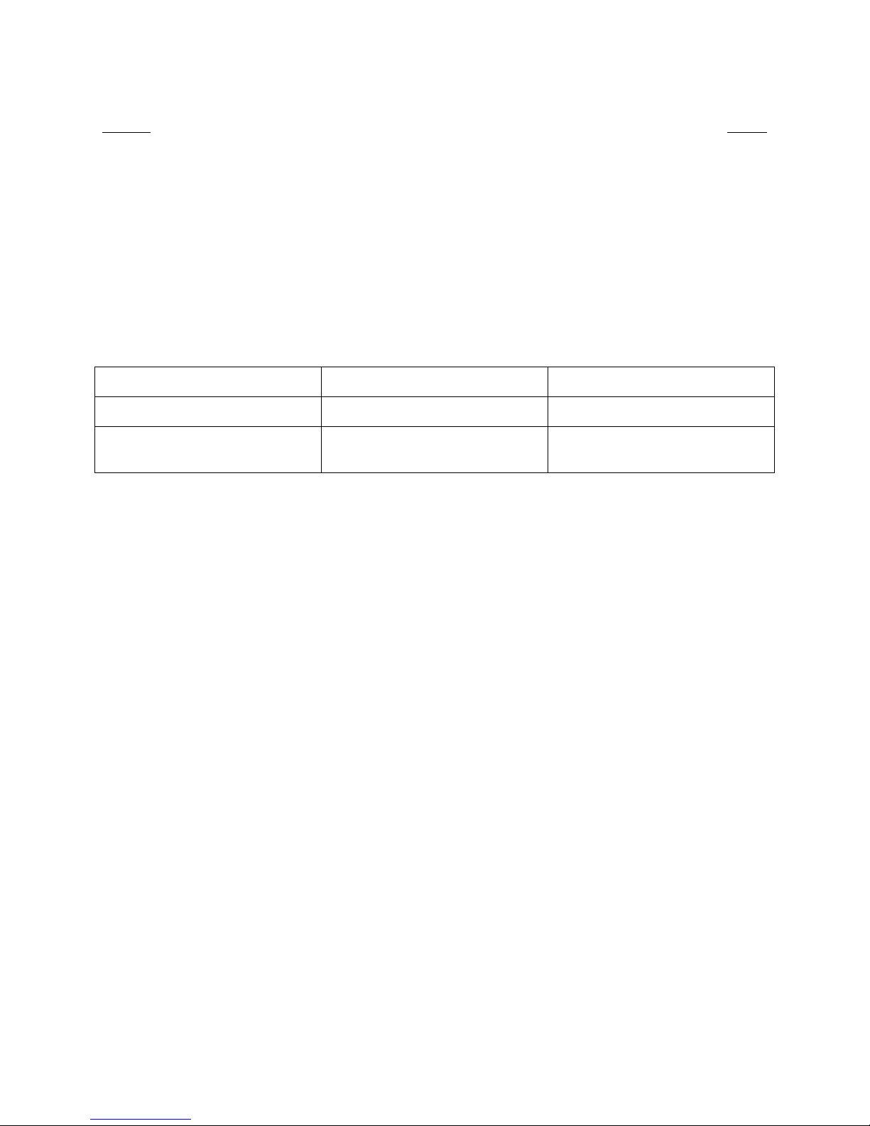
The following table matches the tool size with hardware size:
Tool Size Hardware Size
7/16” ¼”
½” 5/16”
3/8” drive ratchet 7/16” and ½” sockets
7/64” hex key #6-32 sockethead cap screw
M7 M4x20mm screw
TABLE 1

1035930-0001 Revision 2 3-1
3.2 EQUIPMENT
In addition to the tools listed above, the following equipment is recommended to make installation easier:
Hand-held magnetic compass
Angle finder or protractor
Torpedo level
Ladder
See Ku/Ka-Upgradeable Antenna Site Preparation Guide (HNS 1035678) or other site preparation guides for a more
complete list of tools and items that may be needed for installation.

1035930-0001 Revision 2 4-1
4.0 UNPACKING
4.1 UNPACKING
As soon as possible, unpack and inspect the antenna containers to ensure that all material has been received and is
in good condition. An illustration and description of each major component is shown below. The front of the
reflector is covered with a hydrophobic coating. Handle the reflector so that you do not touch this coating
or disturb it in any way. In addition, the feedhorn lens is protected with a styrofoam covering. Do not
remove it until after the antenna assembly is installed on the mount. Do not touch the feedhorn lens.
The hardware kit supplied with the antenna contains the following items:
Item
Q
uantit
y
5/16-18 x 2.00-inch carria
g
e bol
t
2
5/16-18 x 3.00-inch carria
g
e bol
t
2
5/16-inch flat washe
r
4
5/16-inch lock washe
r
4
5/16-18 hex nu
t
4
TABLE 2
There are two possible feed systems available for the antenna. One feed system for an RA6-074 transceiver and
another for an RA6--TG transceiver.
If the antenna is for the RA6-074 transceiver, the following components are included.
Reflector AZ/EL Assembly
2-3/8-inch mast pipe
Feed Support Feed Rods (2) Feed Horn Assembly
(shown assembled)
Feed Horn
Wave
g
uide transition

1035930-0001 Revision 2 4-2
The hardware kit supplied with the RA6-074 feed system contains the following items:
Item
Q
uantit
y
¼-20 x 1.00-inch hex bol
t
5
¼-20 x 3.00-inch hex bol
t
1
¼-inch flat washe
r
12
¼-inch lock washe
r
10
¼-20 hex nu
t
8
¼-20 x .750-inch carria
g
e bol
t
4
5/16-18 x 1.00-inch carria
g
e bol
t
2
5/16-18 x 1.00-inch hex bol
t
2
5/16-inch flat washe
r
4
5/16-inch lock washe
r
4
5/16-18 hex nu
t
2
O-rin
g
2
M4 x 20mm screw 4
M4 lock washe
r
4
To
p
clam
p
1
#6-32 sockethead ca
p
screw 6
#6 internal tooth lock washe
r
6
Silicone
g
rease ca
p
sule 1
TABLE 3
If the antenna is for the RA6-TG transceiver, the following components are included.
The hardware kit supplied with the RA6-TG feed system contains the following items:
Item
Q
uantit
y
¼-20 x 1.00-inch hex bol
t
3
¼-20 x 3.00-inch carria
g
e bol
t
1
¼-inch flat washe
r
8
1/4-inch lock washe
r
4
¼-20 hex nu
t
4
O-Rin
g
1
#6-32 x .50 screw 6
#6 lock washe
r
6
TABLE 4
Upper RA6-074 Mounting
Bracke
t
Lower RA6-074 Mounting
Bracke
t
Feed Support Feed Rods (2)
Feed Horn Assembly

1035930-0001 Revision 2 4-3
4.2 RETURNING COMPONENTS
Any damage to materials while in transit should be immediately directed to the freight carrier. They will instruct
you on the matters regarding any freight damage claims.
Any questions regarding missing or damaged materials that is not due to freight carrier should be directed to the
point of purchase or distributor.

1035930-0001 Revision 2 5-1
5.0 INSTALLATION LOCATIONS
The following antenna installation locations and methods are acceptable:
Non-penetrating mount
Wood frame roofs
Wooden walls
Masonry walls
Pole mount
If the antenna will be used in a Ka system, or will later be upgraded for use in a Ka system, refer to Ku/Ka-Upgradeable
Antenna Site Preparation Guide .98m, 1.2m (HNS 1035678-0001) for instructions on how to select a site and installation
method.
The installation method may be specified in the work order or installation specification.

1035930-0001 Revision 2 6-1
6.0 INSTALLATION PROCEDURES
6.1 CAUTIONS
WARNING
Only HNS-Certified installers can install
DIRECWAY-SP Earth Stations.
All HNS-Certified installers shall have
expressly acknowledged the HNS
requirements for DIRECWAY-SP
installations.
CAUTION
The DIRECWAY-SP ANTENNA
SYSTEM must be installed in a
location or manner not readily
accessible to children and in a
manner that prevents human
exposure to potentially harmful levels
of radiation.
DIRECWAY-SP Antennas mounted in
the Continental United States, Puerto
Rico and any site with greater than a
30 degree elevation angle shall be
mounted such that the lower lip of the
antenna reflector is at least 1.5
meters (no less than 5 feet) above
the high point of any surface, within a
radius of 3.0 meters (10 feet)] upon
which a person might be expected to
stand. DIRECWAY-SP Antennas
mounted in Canada, Alaska, Hawaii,
and any location with lower than a 30
degree elevation angle shall be
installed such that the lower lip of the
satellite dish is at least 1.75 meters (5
feet, 9 inches) above any surface in
proximity of the antenna upon which
a person can be expected to stand.
In addition, the Antennas shall be
mounted such that no object which
could reasonably be expected to
support a person is within 2 meters (6
feet, 7 inches) of the edges of a
cylinder extending from the antenna
reflector in the direction of maximum
radiation.
Alternatively, the antenna must
mounted in an area inaccessible to
the general public, such as a fenced
off enclosure or a roof.
CAUTION
Unplug indoor power connection
before performing maintenance or
adding upgrades to any satellite
dish components.
CAUTION
The surface is covered with
hydrophobic coating.
Do not touch or allow anything to
come in contact with the front
surface of the satellite dish.
Disturbing or damaging the coating
can affect satellite dish
performance.
CAUTION
For enterprise installations, install
the satellite dish assembly using a
non-penetrating mount unless the
customer-specific specification
specifies another method.
Roof installations may void the
building's roof warranty so extreme
care should be exercised. Contact
your HNS installation management
team if you have any questions.
Follow the non-penetrating mount
manufacturer's assembly
instructions.

1035930-0001 Revision 2 6-2
6.2 PROCEDURES
Follow the steps below in the order shown to assemble the antenna. The site elevation, azimuth,
and polarization values should be predetermined and known at this time. Do not tighten any
hardware until instructed to do so. Do not touch the front of the reflector. Remove the protective
bag in a way so that you do not touch the reflector. Do not remove the feedhorn lens covering
until assembly and installation is complete.
Installing the AZ/EL assembly onto the mast pipe
1. Loosen the elevation lock down hardware on both sides of the elevation bracket. See Figure
1.
2. Read the elevation scale and rotate the elevation bracket to the predetermined elevation angle
for the site. Snug down the elevation lock down hardware that was loosened in step #1.
3. Use a ½-inch open-end wrench to loosen the eight canister set screws until they are flush with
the inside wall of the canister. See Figure 2.
4. Place the canister of the AZ/EL assembly onto the mast pipe.
5. Rotate the AZ/EL assembly until the reflector side is oriented in the general direction of the
satellite as shown.
6. Snug the eight canister set screws enough to prevent the assembly from rotating. Do not
tighten until instructed to do so later in the assembly.
Attaching the reflector
1. Orient the reflector so that the feed support attachment interface (3-hole pattern) is at the
bottom. See Figure 3.
2. Lift the reflector and align the four mounting holes in the reflector with the four mounting
holes of the reflector support.
3. Attach by inserting a 5/16-18 x 2.00-inch carriage bolt through each of the two upper
reflector holes and a 5/16-18 x 3.00-inch carriage bolt through each of the lower reflector
holes from the front to the back and through the mounting holes of the reflector support.
AZ/EL
Assembly
Canister Set Screws
Typical 8 Places
Mast Pipe
2-3/8-inches
Hardware on
Both Sides
Lock Down
FIGURE 1
FIGURE 2

1035930-0001 Revision 2 6-3
4. Secure with a flat washer, lock washer, and hex nut on each of the four carriage bolts.
5. Tighten securely.
Installing the feed support, RA6-074 Radio Assembly Models Feed System
1. Place the feed support (length: 34.7 inches) at the bottom of the reflector and align the
mounting hole in the feed support with the center hole in the bottom of the reflector. See
Figure 4.
2. Insert a ¼-20 x 1.00-inch hex bolt and flat washer through the hole in the feed support and
the center hole in the bottom of the reflector.
3. Secure with a flat washer, lock washer and hex nut on the back of the reflector. See Figure 5.
4. Attach one end of each of the (2) feed rods (length: 29.5 inches) to the mounting hole in the
side of the reflector using a ¼-20 x 1.00-inch hex bolt and flat washer. See Figure 6.
5. Secure with a flat washer, lock washer and hex nut on the inside rim of the reflector.
6. Align the opposite end of each feed rod with the mounting hole in the feed support and
connect with a ¼-20 x 3.00-inch hex bolt and flat washer.
7. Secure with a flat washer, lock washer and hex nut on the bolt.
8. Securely tighten these four bolts at this time.
Reflector
5/16-18 x 2.00 –inch
Carriage Bolt
5/16-18 x 3.00-inch
Carriage Bolt
Reflector
Support
Front View Back View
¼ -20 x 1” hex
bolt and washer
FIGURE 3
FIGURE 4 FIGURE 5

1035930-0001 Revision 2 6-4
Attaching the radio assembly
If you need to change the radio’s polarization, refer to Chapter 8 for instructions.
1. If the feed horn assembly is disassembled, you must assemble it. Apply silicone grease to the
feed horn O-ring groove. Then place the O-ring in the groove.
2. Attach the waveguide transition to the feed horn using the six #6-32 sockethead cap screws
and #6 internal tooth lock washers. The feed horn assembly is now complete.
3. Place the O-ring in O-ring groove in the feed horn assembly mounting flange. See Figure 7.
4. Attach the feed horn assembly to the RA6-074 transceiver using the four M4 x 20mm screws
and M4 lock washers in the four holes of the feed horn assembly. Using a plastic handle ball
driver long length, 3mm hex, 6-13/64-inch blade length, makes it easier to reach the screws.
5. Tighten securely.
6. Place the feed horn/RA6-074 transceiver into the upper mounting bracket and secure with (2)
5/16-18 x 1.00-inch hex bolts, flat washers, and lock washers. Tighten securely. See Fig. 8.
7. Place the top clamp over the neck of the feed horn and secure with a ¼-20 x 1.00-inch hex
bolt and lock washer on each side. Tighten securely. See Figure 9.
Feed rods
¼-20 x 3.00-inch hex
bolt with hardware
¼-20 x 1.00-inch
hex bolt and M4
lock washer on
both sides
O-ring
Feed Horn
Assembly
M4 x 20mm
screws and
lock washers
RA6-074
transceiver
FIGURE 6
FIGURE 7

1035930-0001 Revision 2 6-5
8. Place the lower mounting bracket onto the end of the feed support and secure with a 5/16-18
x 1.00-inch carriage bolt from above and flat washer, lock washer, and hex nut from below in
each of the (2) mounting holes. Tighten securely. See Figure 10.
9. Place the feed horn/transceiver/upper bracket assembly from step #4 onto the lower bracket.
10. Assemble by placing a ¼-20 x .750-inch carriage bolt and flat washer through each of the
four mounting holes and secure with a flat washer, lock washer, and hex nut on the bottom.
11. Tighten securely.
5/16-18 x 1.00-inch
hardware
Upper Mounting
Bracket
FIGURE 8
¼-20 x 1.00-inch
hardware
FIGURE 9
¼-20 x .750-inch
carriage bolt with
hardware (4 places)
5/16-18 x 1.00-inch
carriage bolt with
hardware
(
2
p
laces
)
Lower Bracket
Feed Support
Assembly
FIGURE 10

1035930-0001 Revision 2 6-6
Installing the feed support, RA6-TG Radio Assembly Models Feed System
1. Place the feed support (length: 37.6 inches) at the bottom of the reflector and align the
mounting hole in the feed support with the center hole in the bottom of the reflector. See
Figure 11.
2. Insert a ¼-20 x 1.00-inch hex bolt and flat washer through the hole in the feed support and
the center hole in the bottom of the reflector.
3. Secure with a flat washer, lock washer and hex nut on the back of the reflector.
4. Attach one end of each of the (2) feed rods (length: 35.4 inches) to the mounting hole in the
side of the reflector using a ¼-20 x 1.00-inch hex bolt and flat washer. See Figure 12.
5. Secure with a flat washer, lock washer and hex nut on the inside rim of the reflector.
6. Align the opposite end of each feed rod with the mounting hole in the feed support and
connect with a ¼-20 x 3.00-inch hex bolt and flat washer.
7. Secure with a flat washer, lock washer and hex nut on the bolt.
8. Securely tighten these four bolts at this time.
Reflector Inside View
Back View
¼-20 x 1.00-inch
hex bolt with
h
a
r
dwa
r
e
Feed Rods
¼-20 x 1.00-inch
hex bolt with
hardware on both
sides
¼-20 x 3.00-inch
hex bolt with
hardware
FIGURE 11
FIGURE 12

1035930-0001 Revision 2 6-7
Attaching the radio assembly
1. Check the polarization-setting dial on the rear of the RA6-TG transceiver. See Figure 14.
Make sure that it is set to 0°. If not, set it to 0° now. Reference documents provided with
transceiver for instructions for this procedure.
2. Place the O-ring into the O-ring groove in the mounting flange of the feed horn assembly. See
Figure 13.
3. Attach the feed horn assembly to the RA6-TG transceiver using the (6) #6-32 x ½-inch
screws and lock washers.
4. Tighten securely.
5. Place the feed horn/RA6-TG transceiver assembly onto the end of the feed support. See
Figure 14.
6. Align the mounting holes in the transceiver bracket with the holes in the feed support. Secure
with the hardware supplied with the transceiver.
7. Tighten securely.
O-ring
Feed Horn
Assembly
#6-32 x.50-inch
hardware (6 places)
RA6-TG
Feed Support
Hardware Supplied
with Transceiver
FIGURE 14
FIGURE 13
Transceiver Scale
location, transceiver
polarization should
be set to 0° at time
of installation.

1035930-0001 Revision 2 7-1
7.0 ANTENNA POINTING
7.1 POINTING PROCEDURES
This section describes how to point the antenna at the satellite. Correct alignment is critical to the
operation of the system. When the antenna is pointed directly at the satellite, it receives a strong signal.
If it is not positioned properly, the signal may be weak, and errors may result during data transfers. The
signal quality would also deteriorate on cloudy, windy, or rainy days.
The predetermined elevation angle, azimuth heading, and polarization angle should be accurate enough to
allow the antenna to acquire the satellite signal. You may need to refer to the indoor unit (IDU) manual
for other pointing or peaking information
Pre-setting elevation, azimuth, and polarization
1. Using the predetermined elevation angle, which was roughly preset during antenna assembly,
raise or lower the antenna until the angle is read on the elevation scale. Raising the antenna
increases elevation. Lowering it decreases elevation. Rotate the top hex nut on the elevation
adjustment rod sufficiently away from the pinion. Raise the antenna by turning the lower hex nut
of the elevation adjustment rod clockwise. Lower the antenna by turning the hex nut counter-
clockwise.
2. Note that there are two possible pinion mounting slots in the az/el assembly. See Figure 16. The
assembly is shipped with the pinion in the upper mounting slot. This position is for elevation
angles from 0 degrees up to 55 degrees. Fro elevation angles greater than 55 degrees, it will be
necessary to move the pinion to the lower mounting slot before setting elevation.
Elevation Lock
Down Hardware
Elevation Scale
Elevation Lock
Down Hardware
Upper Mounting
Slot
Lower
Mounting Slot
FIGURE 15
FIGURE 16
Table of contents
Other Hughes Network Systems Antenna manuals
Popular Antenna manuals by other brands

Bauhn
Bauhn FPA38558 instruction manual

Shakespeare Electronic
Shakespeare Electronic 2025 manual

Sirius XM RAdio
Sirius XM RAdio XM Indoor installation guide

Directive Systems & Engineering
Directive Systems & Engineering DSE2045LY quick start guide

Philips
Philips SDV8311B/27 user manual

Queclink
Queclink GPS MMCX 3M user guide