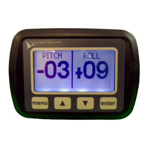
Hummingbird H110 User manual

1
P/N: 7000608 Rev B CO-260 Released Date: 2021-01-19; ©2021, IRRAS USA, Inc. All rights reserved
Instructions for Use
H110
DESCRIPTION:
Hummingbird Parenchymal IntraCranial
Pressure Monitoring Catheter Kit
KIT CONTENTS:
1 Bolted Parenchymal ICP Catheter Kit:
- Parenchymal ICP Monitoring
Catheter
- Bolt with Dilator
- Drill Bit with Collar and Hex
Wrench
1 Skull Thickness Caliper
1 Stab Incision Knife

2
P/N: 7000608 Rev B CO-260 Released Date: 2021-01-19; ©2021, IRRAS USA, Inc. All rights reserved
Table of Contents
LIST OF SYMBOLS AND TERMINOLOGY ............................................................................................3
List of Symbols.............................................................................................................................3
SYSTEM OVERVIEW.............................................................................................................................4
Description....................................................................................................................................4
Indications ....................................................................................................................................4
Contraindications.........................................................................................................................5
Intended User ...............................................................................................................................5
Sterility..........................................................................................................................................5
MR Compatibility..........................................................................................................................5
Shipping........................................................................................................................................5
Storage..........................................................................................................................................5
Procedure Preparation.................................................................................................................8
Step 1 –Estimate Skull Thickness and Prepare the Access Site..............................................8
Step 2 –Prepare the Drill Bit Assembly and Drill........................................................................8
Step 3 –Irrigate the Twist Drill Hole............................................................................................9
Step 4 –Incise the Dura ...............................................................................................................9
Step 5 –Measure Skull Thickness.............................................................................................10
Step 6 - Fixation of Bolt..............................................................................................................10
Step 7 –Ensure Incision is Large Enough for Catheter...........................................................10
Step 8a –Aligning the Catheter to the Bolt ..............................................................................11
Step 8b - Insertion of the Catheter into the Bolt.......................................................................11
Step 9 –Access Completed, Zeroing the ICP Monitoring System and Connecting the
Catheter.......................................................................................................................................11
MAINTENANCE OF THE H110 AND BOLT INSERTION SITE.............................................................13
ICP Lumen Connector Maintenance: ........................................................................................13
CATHETER REMOVAL PROCEDURE.................................................................................................13
Step 1 –Disconnect the Patient Cable Module: .......................................................................13
Step 2 –Removal of the Catheter from the Bolt.......................................................................13
Step 3–Removal of the Bolt ......................................................................................................13
Step 4 –Close surgical site .......................................................................................................14
Recommended Manual Cleaning Method.................................................................................14
Recommended Disinfection Agents..........................................................................................14
TROUBLESHOOTING THE SYSTEM ..................................................................................................14
CONTACTING TECHNICAL SUPPORT...............................................................................................15
MR CONDITIONAL INFORMATION.....................................................................................................17
SKULL THICKNESS CALIPER QUICK GUIDE.....................................................................................18
WARNINGS..........................................................................................................................................19
CAUTIONS...........................................................................................................................................20
WARRANTY............................................................................................................................................20
LIMITATIONS OF LIABILITY ..................................................................................................................20
RETURN GOODS POLICY...................................................................................................................21
ORDERING INFORMATION.................................................................................................................21
IRRAS USA, Inc...........................................................................................................................21

3
P/N: 7000608 Rev B CO-260 Released Date: 2021-01-19; ©2021, IRRAS USA, Inc. All rights reserved
LIST OF SYMBOLS AND TERMINOLOGY
List of Symbols
Symbol
Meaning
Manufacturer
Refer to the Instructions for Use
Expiration Date expressed as year-month-day (yyyy-mm-dd).
Non-Pyrogenic
Do not reuse after opening
Model number
Lot Number
Sterile unless package is open. Method of sterilization –ethylene oxide.
Temperature limits
Relative humidity limits
Keep dry
General Warning
Federal (USA) law restricts this device to sale by or on the order of a physician.
MR Unsafe
MR Conditional (refer to MR Conditional Information section):
•1.5 Tesla
•3.0 Tesla

4
P/N: 7000608 Rev B CO-260 Released Date: 2021-01-19; ©2021, IRRAS USA, Inc. All rights reserved
Terminology
ICP
Intracranial Pressure
ICP Monitoring
System
The system is comprised of the HICP200 and a Hummingbird Catheter (in
the case of this IFU, the Hummingbird Parenchymal ICP Monitoring
Catheter.)
HICP200
The HICP200 is comprised of the Control Module, Patient Cable Module,
Monitor Cable and AC Power Supply.
ICP Lumen
The air lumen that connects the pressure-sensing air bladder to the
pressure transducer located in the Patient Cable Module and provides
communication between the parenchymal ICP monitoring site and the
pressure transducer.
SYSTEM OVERVIEW
Description
The Hummingbird Solo ICP Monitoring device (H110), is an advanced bolted parenchymal ICP
monitoring technology that is designed for accuracy and ease of use. The H110, when used with
HICP200 comprises a system whose principle of operation is based on air-coupled pressure
transduction. The H110 measures ICP with a pressure sensing air bladder located in the
parenchyma. The HICP200 employs air rather than liquid to transduce pressure waves to the
reusable pressure sensor housed in the Patient Cable Module, thus providing for ICP waveform
display and calculation of mean ICP pressure. Refer to the HICP200 Quick Reference Guide
and Instructions For Use (IFU) for operating instructions. The Patient Cable Module requires no
leveling and can be zeroed in-situ. The H110 is packaged in a kit that kit consists of the
following items:
•Parenchymal ICP Monitoring Catheter
•Drill Bit Assembly (consisting of Depth Limiting Collar and 4 mm diameter drill bit) and
hex wrench
•Bolt with Dilator
•Skull Thickness Caliper
•Stab Incision Knife
NOTE: The following required items are not provided by this kit and must be obtained
separately in order to place the H110 and measure ICP:
•A cranial access kit that includes a hand drill
•HICP200 ICP Control Module with the appropriate Monitor Cable for
connection to the patientmonitor
Indications
The H110 is designed for use with HICP200. Together, they comprise a system that is indicated
for use in those conditions where continuous monitoring of ICP is required. The device should
be utilized by a qualified healthcare professional in clinical conditions that warrant direct
measurement of intracranial pressure is clinically important.

5
P/N: 7000608 Rev B CO-260 Released Date: 2021-01-19; ©2021, IRRAS USA, Inc. All rights reserved
Contraindications
Invasive ICP monitoring should not be performed where components of the monitoring
system will come into direct contact with any infected tissue. The H110 is contraindicated:
•When the patient is receiving anticoagulants
•When the patient is known to have a bleeding diathesis
•If trained personnel are not available to continuously supervise ICPmonitoring
Intended User
The H110 is intended to be used by trained and experienced medical and biomedical
professionals:
•A qualified healthcare professional should perform the placement and handling
of the ICP catheter.
•Qualified hospital staff (e.g. neurosurgeon, nurse, intensivist, trauma physician, or
physician’s assistant) should oversee ICP monitoring.
f
IRRAS USA, Inc. recommends that all physicians, nurses, and technicians who will be
using, operating, and maintaining the H110, review the IFU prior to
using the system. If there are additional questions after reading this IFU, contact In
IRRAS USA, Inc.
.
Sterility
This product is provided sterile and is for SINGLE USE ONLY. DO NOT RESTERILIZE.
Kit contents are sterile and non-pyrogenic if package is undamaged and unopened. Do
not re-sterilize. For single-use only—Do not reuse. If opened and unused, discard
immediately.
The H110 has not been designed to undergo or withstand any form of alteration, such as
disassembly, cleaning or re-sterilization, after a single patient use. These devices are
intended to come into contact with the central nervous system and the ability does not
currently exist to destroy possible contaminants such as Creutzfeldt-Jakob Disease
agents. Reuse can also compromise device performance characteristics and any usage
beyond the design intent of this single-use device can result in unpredictable use hazards
or loss of functionality.
MR Compatibility
The Hummingbird H10 has been found to be MR conditional at:
•
1.5 Tesla
•
3.0 Tesla
The HICP200 is MR Unsafe and must not enter the MRI field.
Shipping
Refer to H110 Technical Specifications for shipping conditions.
Storage
Store this product in a cool, dry location, away from direct sunlight. Do not remove the
product from the packaging until it will be used. Refer to H110 Technical Specifications for
storage condition.

6
P/N: 7000608 Rev B CO-260 Released Date: 2021-01-19; ©2021, IRRAS USA, Inc. All rights reserved
COMPONENTS OF THE H110
Depth Limiting
Collar

7
P/N: 7000608 Rev B CO-260 Released Date: 2021-01-19; ©2021, IRRAS USA, Inc. All rights reserved
H110 INSERTION PROCEDURE SUMMARY FIGURES

8
P/N: 7000608 Rev B CO-260 Released Date: 2021-01-19; ©2021, IRRAS USA, Inc. All rights reserved
H110 INSERTION PROCEDURE INSTRUCTIONS
Procedure Preparation
•The following supplies are required:
−H110 Solo ICP Monitoring device
−A cranial access kit that includes a hand drill
−HICP200 with the correct monitor cable for connection to the patient monitor
•Ensure the HICP200 has been properly prepared for the procedure. (For details see the
Maintenance and Care section for the HICP200.)
•Connect the HICP200 to the patient monitor a minimum 15 minutes before beginning the
procedure to allow the transducer to rise to an equilibrium temperature.
•Open the H110 kit using aseptic technique.
Step 1 –Estimate Skull Thickness and Prepare the Access Site
•Select the catheter insertion site for access to the parenchyma.
•Estimate skull thickness using CT scan(s).
•The operative site should be aseptically cleaned and draped.
NOTE: To minimize risk of surgical site infections, it is recommended to prepare the
surgical area in accordance with evidenced-based guidelines, such as Mangram
et al. Guideline for Prevention of Surgical Site Infection, 1999. Infection Control
and Hospital Epidemiology, 20(4), pp. 257-258 and Nichols RL. Preventing
Surgical Site Infections: A Surgeon’s Perspective. Emerging Infectious
Diseases. 7(2), Mar-Apr 2001.
•Make an incision in the scalp and expose the bone with a self-retaining type retractor, or
similar device.
Step 2 –Prepare the Drill Bit Assembly and Drill
•Adjust the Drill Bit Assembly by loosening the set screw on the Depth Limiting Collar with
the provided hex wrench.
•Position the Depth Limiting Collar, exposing the tip of the drill just enough to completely
drill through the skull’s inner table according to the CT scan estimated skull thickness.
Ensure that the set screw is tight enough to prevent movement of the Depth
Limiting Collar on the Drill Bit. However, do not over-torque the set screw.
•Drill a hole in skull using drill bit provided within the kit.

9
P/N: 7000608 Rev B CO-260 Released Date: 2021-01-19; ©2021, IRRAS USA, Inc. All rights reserved
Do not change the angle of the drill while drilling, as this could cause the hole to
become too wide or conical.
Care should be exercised to prevent excessive penetration and/or damage to
the dura, cortex, and cortical vessels.
Step 3 –Irrigate the Twist Drill Hole
•Irrigate the drill hole with sterile saline, ensuring that it is cleared of any debris and/or
bone shards.
Bone shards must be removed prior to catheter insertion. Failure to remove
bone shards may damage the catheter’s pressure-sensing bladder.
Step 4 –Incise the Dura
•Open the dura by making a cruciate incision, using the stab incision knife (provided in
the Hummingbird Solo ICP Monitoring or equivalent). Recommended: use the Dilator
provided within the kit, to ensure the incision is large enough to accommodate the
catheter.
Failure to properly incise the dura could cause the catheter’s pressure-sensing
bladder tear during insertion of the H110 and performance to be compromised.

10
P/N: 7000608 Rev B CO-260 Released Date: 2021-01-19; ©2021, IRRAS USA, Inc. All rights reserved
Step 5 –Measure Skull Thickness
Refer to the Skull Thickness Caliper Quick Guide section of this IFU to. Measure the skull thickness.
Step 6 - Fixation of Bolt
•Position the Bolt in the drill hole.
•To advance the Bolt, screw the Bolt clockwise in skull to the depth of the measured skull
thickness.
If the bolt is loose, the insertion procedure must be repeated at a new site.
NOTE: One full turn (360°) of the bolt advances the bolt 1mm into the skull.
Step 7 –Ensure Incision is Large Enough for Catheter
•Advance the dilator through the bolt to ensure the incision is large enoughto
accommodate the catheter.

11
P/N: 7000608 Rev B CO-260 Released Date: 2021-01-19; ©2021, IRRAS USA, Inc. All rights reserved
Step 8a –Aligning the Catheter to the Bolt
•Holding the catheter by the blue insert, align the insert’s ribs to the Bolt’s slot (it can fit
in one of two positions).
Step 8b - Insertion of the Catheter into the Bolt
•Press down on the insert firmly until the catheter snaps into the bolt.
Step 9 –Access Completed, Zeroing the ICP Monitoring System and Connecting the
Catheter
•Ensure the patient monitor has been zeroed per the HICP200 IFU, remembering to
disconnect the ICP lumen connector, if connected. The Patient Cable Module Protective
Connector can be left in place, as it is vented. The objective is to ensure that the Patient
Cable Module is open to atmosphere.
Disconnect the ICP catheter from the Patient Cable Module prior to zeroing
the patient monitor, as failure to do so may result in inaccuracy. The Patient
Cable Module must communicate with atmospheric pressure when zeroing the
patient monitor.
•Connect the ICP lumen connector to the HICP200 Patient Cable Module. A secure
connection can be confirmed by a tactile and audible indication.
•Operate the HICP200 (figure below) per its instructions for use.

12
P/N: 7000608 Rev B CO-260 Released Date: 2021-01-19; ©2021, IRRAS USA, Inc. All rights reserved
The HICP200 Control Module, Monitor Cable, Patient Cable Module and
AC Adaptor are MR-unsafe and must not enter the MRI field.

13
P/N: 7000608 Rev B CO-260 Released Date: 2021-01-19; ©2021, IRRAS USA, Inc. All rights reserved
MAINTENANCE OF THE H110 AND BOLT INSERTION SITE
In general, there is a risk of infection due to use of intracranial catheters. It is
recommended that the H110 not be left in place for more than 5 days.
ICP Lumen Connector Maintenance:
Before cleaning the surface of the ICP Lumen Connector, note the following:
•Use particular care when cleaning around the connectors. Be sure to wipe any
excess fluid that accumulates in these areas.
•Always protect the HICP200 Plug when the catheter is disconnected from the
HICP200 Patient CableModule.
Caution: The ICP Lumen Connector must be kept dry. Always protect the catheter
connector when the catheter and HICP200 Patient CableModule are
disconnected
Maintain the Bolt insertion site during ICP monitoring according to standard hospital
protocol. Avoid pulling on any of the lines or cables attached to the Bolt or Catheter. Avoid
striking the Bolt.
CATHETER REMOVAL PROCEDURE
Step 1 –Disconnect the Patient Cable Module:
•Disconnect the catheter from the Patient Cable Module.
•Before insertion of any components in the Patient Cable Module, inspect the
connection port. Use an IPA-moistened (dampened) swab to ensure that any debris
has been carefully removed.
Step 2 –Removal of the Catheter from the Bolt
•Holding the bolt in one hand and the catheter in the other hand by its blue insert, pull the
catheter straight from the bolt.
•Remove and dispose of the catheter per hospital protocol.
Step 3–Removal of the Bolt
•Turn the bolt counter-clockwise to remove it from the skull.

14
P/N: 7000608 Rev B CO-260 Released Date: 2021-01-19; ©2021, IRRAS USA, Inc. All rights reserved
Step 4 –Close surgical site
•Close cranial access site per standard hospital procedure.
Step 5 –Cleaning and care of the HICP200 and its components.
•Reference the HICP200 IFU (a summary is provided below).
MAINTENANCE AND CARE OF THE HICP200
It is recommended that the Control Module and its components be cleaned as soon as is
reasonably practical after use. Reference HICP200 IFU for maintenance and cleaning
procedures.
Inspect the HICP200 and the cables for wear or damage (e.g., frayed power cord, pinched
cable, or cracked enclosure). Do NOT use the HICP200 if there is any sign of wear or damage.
Do not autoclave, use automated cleaning methods, or immerse the Control Module in
liquid as damage may occur. If the Control Module is exposed to liquids, remove the AC
Power Supply, dry the unit thoroughly, and send to biomed staff for evaluation before
reapplying power.
Recommended Manual Cleaning Method
Using either 70% IPA with a lint free wipe or a Diversey Oxivir-Tb Wipes®, thoroughly wipe
all surfaces at least three (3) times and then inspect the surfaces for visible residues. If
residues remain, use a new Diversey Oxivir-Tb Wipes® or lint free wipe soaked with 70%
IPA and continue wiping the surfaces until they are visibly free of residues.
Recommended Disinfection Agents
The HICP200 has been tested and shown to withstand exposure to 70% IPA and Diversey
Oxivir-Tb Wipes®. If used follow standard hospital procedures and manufacturer’s
instructions for use.
TROUBLESHOOTING THE SYSTEM
Complete the following steps until the problem is resolved:
Check the ICP Lumen Connector
The HICP200 Patient Cable Module and ICP Lumen Connector must be kept dry. Fluid that
enters the connector may cause a dampened or flat pressure waveform and/or an inaccurately
high-pressure reading. Visually inspect the filter within the ICP Lumen Connector and replace
as required.
Re-zero the HICP200
When in Prime Mode, Priming Mode, Run Mode, or Fault Mode, press the “STOP” button to go
to Zero Wait Mode and clear any error code. Press the “STOP” button and disconnect the ICP
Lumen Connector from the Patient Cable Module. Perform the standard protocol for zeroing the
patient monitor.

15
P/N: 7000608 Rev B CO-260 Released Date: 2021-01-19; ©2021, IRRAS USA, Inc. All rights reserved
Disconnect the ICP catheter from the Patient Cable Module prior to zeroing the
patient monitor, as failure to do so may result in pressure offset and inaccuracy. The
Patient Cable Module must communicate with atmospheric pressure when zeroing the
patient monitor.
Confirm that the HICP200 is powered on by checking the indicator lights.
If the HICP200 has no light indication, ensure the Monitor Cable is properly connected to the
patient monitor and the monitor is turned on. If the HICP200 is plugged into the patient monitor
and has no light indication, (a) plug the AC Power Supply Cable into a compatible outlet, (b)
plug the HICP200 into a separate patient monitor module or (c) replace the HICP200 Monitor
Cable.
If there is a large change in ICP pressure and waveform, press “PRIME SYSTEM” button on the
HICP200.
If the previous trouble shooting steps did not result in a change in status, replace the HICP200.
If none of the above steps remedy the problem, consideration should be given to replace the
catheter.
For additional information on troubleshooting, cleaning, and use questions regarding the
HICP200, please consult the HICP200 IFU.
CONTACTING TECHNICAL SUPPORT
If any component of the ICP Monitoring System fails to perform as specified, and the cause
cannot be determined, contact IRRAS USA, Inc. for technical support:
IRRAS USA, Inc
San Diego, CA 92130
TEL: 1(800) 213-4604
US.customerservice@irras.com
IRRAS GmbH
Prielmayerstr. 3
DE-80335 München Germany
Tel: +31-73-303 5509
Global.custome[email protected]

16
P/N: 7000608 Rev B CO-260 Released Date: 2021-01-19; ©2021, IRRAS USA, Inc. All rights reserved
H110 TECHNICAL SPECIFICATIONS
Item
Specification
Principle Technology
Pressure Sensor Type: Solid State strain gauge pressure
transducer
Operating
Atmospheric
Pressure (Absolute)
600 to 800 mmHg
Operation Limits
•Temperature = 15 °C to 39 °C
•Humidity = 15% to 95% relative humidity, non-condensing
Shipping/Storage
Limits
•Temperature = 5 °C to 40 °C
•Humidity = Relative humidity ranging from 5% to 95% non-
condensing
Rated ICP Accuracy
Range
0 to 100 mmHg
Rated Pressure
Accuracy
±2 mmHg or 10% whichever is greater
NOTE: ±2 mmHg from 0-20 mmHg and ±10% from 20 to 100 mmHg (per
ANSI / AAMI NS28)
Time of Use (for
Assured Accurate
Performance)
To maintain accuracy, re-prime is required if the Hummingbird ICP is
exposed to a 10 °C (or greater) or 25%RH (or greater) change.
Stability over
Temperature Range
of 20 to 39°C (68 to
102°F):
Stable if used within 10 °C and 25%RH of initial set-up. NOTE: Re-
prime required if exposed to a 10 °C (or greater) or 25%RH (or
greater) change.
Drift of the Zero Point
Reading
The zero point drift does not exceed ±0.15 mmHg per 24 hour period.
Re-zeroing the transducer can be performed in-situ and is
recommended if the user operates the system outside of the
manufacturer’s recommendations (temperature or barometric pressure)
or the user questions the pressure value displayed on
the patient monitor.
Maximum Frequency
Response *
11Hz
Slew Rate *
220 mmHg/sec (zero to peak), 180 mmHg/sec (peak to zero)
Time Constant for Full
Scale Deflection
of the System **
0.045 sec
Catheter Size
5.5 French (0.073”)
Drill Hole
4 mm (0.156”)
* Lowest maximum frequency/slew rate response measured at 10, 20, and 50 mmHg
** Approximate time constant measured at 10, 20, and 50 mmHg (increasing and decreasing
pressures)

17
P/N: 7000608 Rev B CO-260 Released Date: 2021-01-19; ©2021, IRRAS USA, Inc. All rights reserved
MR CONDITIONAL INFORMATION
Non-clinical testing has demonstrated the bolt and catheter is MR-Conditional. A patient
with this device can be scanned safely in an MR system under the following conditions:
•Static magnetic field of 1.5 Tesla and 3 Tesla, only
•Maximum spatial gradient magnetic field of 4,000 Gauss/cm (40 Tesla/m)
•Maximum MR system reported, whole body averaged specific absorption rate (SAR) of
2 W/kg for 15:00 minutes of scanning (i.e. per pulse sequence) in the Normal
Operating Mode
MR RF Induced Heating
Under the scan conditions defined, the bolt and catheter are expected to produce a
maximum temperature rise of 1.8˚C after 15 minutes of continuous scanning (i.e., per
pulse sequence).
Image Artifact
In non-clinical testing, the image artifact caused by the bolt and catheter extends
approximately 7mm from this implant when imaged using a gradient echo pulse sequence
and a 3 Tesla MR system.
The HICP200 Control Module, Power Supply, and all electrical cables (e.g.
Monitor Cable, Patient Cable Module) have not been tested for MR
Compatibility and are therefore MR-Unsafe and should never enter the MRI
field.

18
P/N: 7000608 Rev B CO-260 Released Date: 2021-01-19; ©2021, IRRAS USA, Inc. All rights reserved
SKULL THICKNESS CALIPER QUICK GUIDE

19
P/N: 7000608 Rev B CO-260 Released Date: 2021-01-19; ©2021, IRRAS USA, Inc. All rights reserved
WARNINGS
Note: Failure to observe one or more of the following warnings could compromise patient
safety or result in ICP measurement errors.
Kit contents are sterile and non-pyrogenic if package is undamaged and unopened. Do
not re-sterilize. For single-use only—Do not reuse. If opened and unused, discard
immediately.
•When the patient is receiving anticoagulants
•When the patient is known to have a bleeding diathesis
•If trained personnel are not available to continuously supervise ICPmonitoring
•The Hummingbird H110 is not recommended for skull thicknesses less than 4 mm.
IRRAS USA, Inc. recommends that all physicians, nurses, and technicians who will
be using, operating, and maintaining the H110, review the IFU prior to using the
system. If there are additional questions after reading this IFU, contact IRRAS USA,
Inc..
The H110 has not been designed to undergo or withstand any form of alteration, such as
disassembly, cleaning or re-sterilization, after a single patient use. These devices are
intended to come into contact with the central nervous system and the ability does not
currently exist to destroy possible contaminants such as Creutzfeldt-Jakob Disease
agents. Reuse can also compromise device performance and any usage beyond the
design intent of this single-use device can result in unpredictable use hazards or loss of
functionality.
The HICP200 Control Module, Monitor Cable, Patient Cable Module and AC
Adaptor must not enter the MRI field.
Ensure that the set screw is tight enough to prevent movement of the Depth Limiting
Collar on the Drill Bit. However, do not over-torque the set screw.
Do not change the angle of the drill while drilling, as this could cause the hole to become
too wide or conical.
Care should be exercised to prevent excessive penetration and/or damage to the dura,
cortex, and cortical vessels.
Bone shards must be removed prior to catheter insertion. Failure to remove bone shards
may damage the catheter’s pressure-sensing bladder.
Failure to properly incise the dura could cause the catheter’s pressure-sensing
bladder to tear during insertion of the H110.
If the bolt is too loose, the insertion procedure must be repeated at a new site.

20
P/N: 7000608 Rev B CO-260 Released Date: 2021-01-19; ©2021, IRRAS USA, Inc. All rights reserved
Disconnect the ICP catheter from the Patient Cable Module prior to zeroing the
patient monitor, as failure to do so may result in inaccuracy. The Patient Cable Module
must communicate with atmospheric pressure when zeroing the patient monitor.
In general, there is a risk of infection due to use of intracranial catheters. It is
recommended that the H110 not be left in place for more than 5 days.
Do not autoclave, use automated cleaning methods, or immerse the Control Module in
liquid as damage may occur. If the Control Module is exposed to liquids, remove the AC
Power Supply, dry the unit thoroughly, and send to biomed staff for evaluation before
reapplying power.
CAUTIONS
Note: Caution statements are used to highlight information relating to special care that should
be exercised to ensure the safe and effective use of the ICP Monitoring System.
•The ICP Lumen Connector must be kept dry. In the event liquid enters the ICP Lumen
Connector, a filter inside the connector will turn blue, indicating that the ICP Lumen
Connector needs to be replaced. Ensure the ICP Protective Cap is installed on the ICP
Lumen Connector when not connected to the HICP200.
•Any serious incident that has occurred in relation to the device should be reported to the
manufacturer and the competent authority of the Member State in which the user and/or
patient is established.
IRRAS WARRANTY
WARRANTY
All devices bearing the IRRAS USA, Inc. brand are guaranteed to be free of functional defects in
workmanship and materials when used normally for their intended surgical use. Any IRRAS
USA, Inc. device proving to be defective will be replaced. Any type of misuse or abuse will
render the warranty void. IRRAS USA, Inc. assumes no liability if the device is misused.
LIMITATIONS OF LIABILITY
IRRAS USA, Inc. has exercised reasonable care in the manufacture of this device. IRRAS
USA, Inc. excludes all warranties, whether expressed or implied by operation of law or
otherwise, including, but not limited to, any implied warranties of MERCHANTABILITY or
FITNESS, since storage and handling of this device by the user, as well as other factors
relating to the patient, the diagnosis, treatment, surgical therapy, and other matters beyond
IRRAS USA, Inc. control directly affect this device and the results obtained from its use.
IRRAS USA, Inc. will not be liable for INCIDENTAL or CONSEQUENTIAL LOSS, DAMAGE,
or EXPENSE directly or indirectly arising from the use of this device. IRRAS USA, Inc.
neither assumes, nor authorizes any other person to assume for it, any other or additional
LIABILITY or RESPONSIBILITY in connection with this device.
IRRAS USA, Inc. makes no claim for or representations as to the performance characteristics of
this product if it is used in conjunction with components of other manufacturers.
Table of contents
Other Hummingbird Measuring Instrument manuals
Popular Measuring Instrument manuals by other brands

thermastor
thermastor Humiport 10 owner's manual

ABQINDUSTRIAL
ABQINDUSTRIAL HT-4000 user guide

Aqua Medic
Aqua Medic T Controller HC Operation manual

Mini?Cam
Mini?Cam Proteus Lite Original instruction manual

SureShot
SureShot PINLOC 5000i user manual

Hellermann Tyton
Hellermann Tyton 2608 operating instructions