Hunt CCTV HTZ-1000ISWBH User manual

INSTRUCTION MANUAL Ver 1.1
Mini Speed Dome Camera

Speed Dome Camera Instruction Manual 2/41
This lightning flash with arrowhead symbol is intended to alert the user to the
presence of un-insulated "dangerous voltage" within the product's enclosure that
may be of sufficient magnitude to constitute a risk of electric shock to persons.
This exclamation point symbol is intended to alert the user to the presence of
important operating and maintenance (servicing) instructions in the literature
accompanying the appliance.
This Device compiles with Part 15 of the FCC Rules. Operation is subject to the
following two conditions:
(1) This device may not cause harmful interface, and
(2) This devides must accept any interference received, including interference that
may cause undesired operations.

Speed Dome Camera Instruction Manual 3/41
Important Safeguard
1. Read Instructions
Read all of the safety and operating instructions before using the product.
2. Retain Instructions
Save these instructions for future reference.
3. Attachments / Accessories
Do not use attachments or accessories unless recommended by the appliance manufacturer as they may
cause hazards, damage product and void warranty.
4. Installation
Do not place or mount this product in or on an unstable or improperly supported location. Improperly
installed product may fall, causing serious injury to a child or adult, and damage to the product. Use only
with a mounting device recommended by the manufacturer, or sold with the product. To insure proper
mounting, follow the manufacturer's instructions and use only mounting accessories recommended by
manufacturer.
5. Power source
This product should be operated only from the type of power source indicated on the marking label.
Precautions
Operating
zBefore using, make sure power supply and others are properly connected.
zWhile operating, if any abnormal condition or malfunction is observed, stop using the camera
immediately and then contact your local dealer.
Handling
zDo not disassemble or tamper with parts inside the camera.
zDo not drop or subject the camera to shock and vibration as this can damage camera.
zCare must be taken when you clean the clear dome cover. Especially, scratch and dust will ruin your
quality of camera.
Installation and Storage
zDo not install the camera in areas of extreme temperature, which exceed the allowable range.
zAvoid installing in humid or dusty places.
zAvoid installing in places where radiation is present.
zAvoid installing in places where there are strong magnetic fields and electric signals.
zAvoid installing in places where the camera would be subject to strong vibrations.
NOTICENOTICENOTICENOTICENOTICENOTICENOTICENOTICENOTICENOTICENOTICENOTICENOTICENOTICENOTICE

Speed Dome Camera Instruction Manual 4/41
○
1Introduction
Features 5
Product&Accessories 7
PartsName&Functions 8
○
2Installation
DIPSwitchSetup 9
InstallationusingSurfaceMountBracket 12
Installation using Ceiling Mount Bracket 13
InstallationusingWallMountBracket 14
Cabling 15
○
3Operation
CheckingBeforeOperation 17
PresetandPatternFunctionPre-Check 17
Start OSD Menu
18
Reserved Preset
18
Preset
19
Swing
19
Pattern
20
Group
21
Other Functions
22
OSD Display of Main Screen
23
○
4How to use OSD Menu
General Rules of Menu Operation
24
Main Menu
24
Display Menu for Main Screen
25
Privacy Zone Mask Setup
26
Camera Module Setup
27
Motion Setup
30
Preset Setup
33
Swing Setup
35
Pattern Setup
36
Group Setup
37
System Initialize
39
8
○
5Specifications
40
Dimension
41
CONTENTS

Speed Dome Camera Instruction Manual 5/41
Featur e s
Camera Specifications
zCCD Sensor : 1/4" Interline Transfer CCD
zZoom Magnification : ×10 Optical Zoom, ×10 Digital Zoom (Max ×100 Zoom)
zDay & Night Function
zVarious Focus Mode : Auto-Focus / Manual Focus / Semi-Auto Focus.
zIndependent & Simultaneous Camera Characteristic Setup in Preset operation
Powerful Pan/Tilt Functions
zMax. 360°/sec high speed Pan/Tilt Motion
zUsing Vector Drive Technology, Pan/Tilt motions are accomplished in a shortest path. As a result,
time to target view is reduced dramatically and the video on the monitor is very natural to watch.
zFor jog operation using a controller, since ultra slow speed 0.05°/sec can be reached, it is very easy
to locate camera to desired target view. Additionally it is easy to move camera to a desired position
with zoom-proportional pan/tilt movement.
Preset, Pattern, Swing, Group, Privacy Mask and More…
zMAX. 127 Presets are assignable and characteristics of each preset can be set up independently,
such as White Balance, Auto Exposure, Label and so on.
zMax. 8 set of Swing action can be stored. This enables to move camera repetitively between two
preset positions with designated speed.
zMax. 4 of Patterns can be recorded and played back. This enables to move camera to follow any
trajectory operated by joystick as closely as possible.
zMax. 8 set of Group action can be stored. This enables to move camera repetitively with
combination of Preset or Pattern or Swing. A Group is composed of max. 20 entities of
Preset/Pattern/Swings.
zPrivacy Masks are assignable, not to intrude on other’s privacy. (4 Privacy Zones)
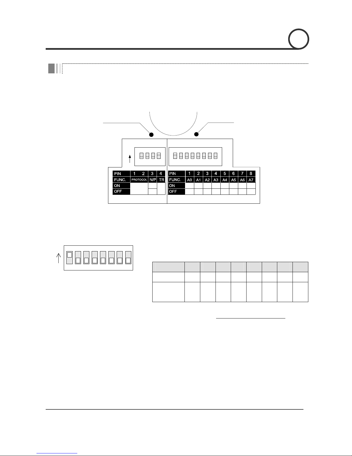
PTZ(Pan/Tilt/Zoom) Control
zWith RS-485 communication, max. 255 of cameras can be controlled at the same time.
zPelco-D or Pelco-P protocol can be selected as a control protocol in the current version of firmware.
INTRODUCTION 1

Speed Dome Camera Instruction Manual 6/41
OSD(On Screen Display) Menu
zOSD menu is provided to display the status of camera and to configure the functions interactively.
zThe information such as Camera ID, Pan/Tilt Angle, Alarm Input and Preset can be displayed on
screen.
Alarm I/O Functions
z4 alarm sensor Inputs are available.
zTo reject external electric noise and shock perfectly, alarm sensor Input is decoupled with photo
coupler.
zThe signal range of sensor input is from DC 5.0 to 12.0 volts to adopt various applications.
zA camera can be set to move to a Preset position or to run functions such as Pattern, Swing and
Group when there are external sensor activations. Also “Post Alarm” function can be set, which is
supposed to activate after pre-defined time period and sequentially in succession to the action by
external sensor activation.
Reserved Presets for Special Purpose
zMost camera characteristics can be set up easily and directly with reserved preset, not entering
into OSD menu. For more information, refer to “Reserved Preset” in this manual.
Easy Installation and Perfect Outdoor Environment Compatibility
zFans and heaters are built-in in camera for cold and hot temperature environment. Also idealistic
mechanical design protects camera from water and dust. (IP66 when installed properly with wall
mount bracket only)
zIt is easy to install and repair camera.
INTRODUCTION 1

Speed Dome Camera Instruction Manual 7/41
Product & Accessories
zMain Body zAccessory
(Terminal Block, BNC Cable,Wrench, Screws)
Options
zSurface Mount Bracket zWall Mount Bracket zCeiling Mount Bracket
INTRODUCTION 1

Speed Dome Camera Instruction Manual 8/41
Parts Name & Functions
Mounting Hole
Dome Cover
Lockup Screw
Main Body
Mount Bracket
D
rop Preventio
n
Spring
Assemble
Reference Line
DIP Switch
Cabling
Terminal Block
Drop Preventio
n
Spring Hook
zMain Unit / Surface Mount Bracket zBack of Main Unit
zDome Cover Do not detach protection vinyl from dome cover before finishing all
installation process to protect dome cover from scratches or dust.
zMount Bracket Used to install camera on surface of ceiling or wall. There are 3 types of
installation.(Surface Mount Type, Wall Mount Type and Ceiling Mount
Type) When installing, install brackets first and then install Main Body.
zLockup Screw Fixes main unit to surface mount bracket.
zCabling Terminal Block During installation, Power, Video, Communication, Alarm Input cables
are connected on to this cabling terminal block.
zDIP Switch Adjusts camera ID and protocols.
zDrop Prevention Spring
Keeps the camera from dropping during installation and repair. After
installing a bracket, hang the spring to the drop prevention hook of
Main Body as shown in the following picture for further tasks.
zAssemble Reference Line Mark to assemble Main Body to bracket.
INTRODUCTION 1

Speed Dome Camera Instruction Manual 9/41
DIP Switch Setup
Before you install the camera, you should set the DIP switches to configure the camera ID, communication
protocol.
Camera ID
ON
ADDRESS (ID)
OPTIONS
1 2 4 8 16 32 64 128
00000000
Refer to
the Manual
PAL
NTSC
Communicatio
n
Protocol
Terminal
Resistor
Camera ID Setup
123456
ON
ON
78
zID number of camera is set using binary number. The example is
shown bellow.
Pin 1 2 3 4 5 6 7 8
ID Value 1 2 4 8 16 32 64 128
ex) ID=5 on off on off off off off off
ex) ID=10 off on off on off off off off
zThe range of ID is 1~255. Do not use 0 as camera ID. Factory
default of Camera ID is 1.
zIf you want to control a certain camera, you must match the camera
ID with Cam ID setting of DVR or Controller.
INSTALLATION 2

Speed Dome Camera Instruction Manual 10/41
Communication Protocol Setup
1234
ON
ON
NTSC/PAL (Reserved for Supplier)
1234
ON
O
N
zSelect the appropriate Protocol with DIP switch combination.
Switch State
P0
(Pin 1)
P1
(Pin 2)
Protocol
OFF OFF PELCO-D, 2400 bps
ON OFF PELCO-D, 9600 bps
OFF ON PELCO-P, 4800 bps
ON ON PELCO-P, 9600 bps
zIf you want to control using DVR or P/T controller, their protocol must
be identical to camera. Otherwise, you can not control the camera.
zIf you changed camera protocol by changing DIP S/W, the change
will be effective after you reboot the camera.
zFactory default of protocol is “Pelco-D, 2400 bps”.
zSince Pin 3 is only for supplier, DO NOT CHANGE THESE ITS
ORIGINAL STATE.If you change one of these, proper operation can
not be achieved.
~Pin 3 PAL / NTSC system selection of Camera. DO NOT
CHANGE THIS PIN.
INSTALLATION 2

Speed Dome Camera Instruction Manual 11/41
Terminal resistor Setup
1234
ON
ON
T
erminal resistor is used if your system is one of following two cases.
zCase1: Control cable between camera and controller is
relatively very long (1:1 connection)
If communication cable is very long, the electrical signal will bound
in the terminal point. This reflected signal cause distortion of
original signal. Accordingly, the camera can be out of control. In this
case, the terminal resistor of both sides i.e. camera and controller
must be set to ‘ON’ state.
zCase2: Multiple cameras are controlled at the same time
Due to similar reasons with case 1, the terminal resisters of
controller and the last camera must be set to ‘ON’ state. Last camera
means decided by cable length. Do not turn on the terminal resistor
of all cameras.
Controller
#1 #2 #n
Terminal Resistor ON
RS-485
Terminal Resistor
OFF
Terminal Resistor
OFF
Terminal Resistor
ON
INSTALLATION 2

Speed Dome Camera Instruction Manual 12/41
Installation using Surface Mount Bracket
①To pass cables through to upside of ceiling, make
a hole whose diameter is about 50~60mm on the
ceiling panel.
②
A
fter assembling Rubber Gasket to Mount
Cover, install Mount Cover on surface of ceiling
panel.
③Hook up “Drop Prevention Spring” on main body
to prevent camera from unexpected drop and
connect cables to Main Body with terminal
blocks.
④Check the 2 mold line for assembly before
starting assembly. Line up the mold lines as
shown in the circle shown below and assemble
Main Body to Mount Cover. Then screw up the 4
screws with wrench included in the product box
and detach the vinyl on dome cover
### Important Notice ###
•Before starting installation, make sure that Camera ID and Protocol are set up properly.
•When the pipe hole on side of Mount Bracket is not used, make sure that the hole is closed properly.
2
INSTALLATION
W
rench

Speed Dome Camera Instruction Manual 13/41
Installation using Ceiling Mount Bracket
①To pass cables through to upside of ceiling, make
a hole whose diameter is about 50~60mm on the
ceiling panel. Then attach the Ceiling Mount Bracket
on.
②Turn camera housing on its axis in
CW(Clockwise) direction until it stops.
③Hook up “Drop Prevention Spring” on main body
to prevent camera from unexpected drop and
connect cables to Main Body with terminal blocks.
④Check the 2 mold line for assembly before
starting assembly. Line up the mold lines as
shown in the circle shown below and assemble
Main Body to Ceiling Mount Bracket. Then screw
up the 4 screws with wrench included in the
product box and detach the vinyl on dome cover.
### Important Notice ###
•Before starting installation, make sure that Camera ID and Protocol are set up properly.
•To adjust the location of camera, pipe and coupler should be needed. Note that they should not be included
in the product box and not supplied by manufacturer
INSTALLATION 2
W
rench

Speed Dome Camera Instruction Manual 14/41
Installation using Wall Mount Bracket
①To pass cables through to inside of wall, make a
hole whose diameter is about 50~60mm on the
wall. Then attach the Wall Mount Bracket with
gasket on it.
②Hook up “Drop Prevention Spring” on main body
to prevent camera from unexpected drop and
connect cables to Main Body with terminal blocks.
③Check the 2 mold line for assembly before
starting assembly. Line up the mold lines as
shown in the circle shown below and assemble
Main Body to Wall Mount Bracket.
④ Then screw up the 4 screws with wrench included
in the product box and detach the vinyl on dome
cover.
### Important Notice ###
•Before starting installation, make sure that Camera ID and Protocol are set up properly.
•When the pipe hole on side of Mount Bracket is not used, make sure that the hole is closed properly
INSTALLATION 2
W
rench

Speed Dome Camera Instruction Manual 15/41
Cabling
Power
IN COM+
IN1
IN2
IN3
IN4
PWR(+)
PWR(-)
F.G
RS-485(+)
RS-485(-)
Cabling Terminal Block
VIDEO(+)
VIDEO(-)
Controller/ DVR
Moinitor
BNC Sensor
IrDA
Sensor
Door
Switch
Power Connection
zPlease, check the voltage and current capacity of rated power carefully. Rated power is indicated in the
back of main unit.
Rated Power Input Voltage Range Current Consumption
DC 12V DC 11V ~ 18V 2.5 A (Fan/Heater Model)
AC 24V AC 17V ~ 29V 1.5 A (Fan/Heater Model)
RS-485 Communication
zFor PTZ control, connect this line to keyboard and DVR. To control multiple cameras at the same time,
RS-485 communication lines of them is connected in parallel as shown below.
K
eyboard Controller / DVR
RS-485
+
-
#1
+
-
#2
+
-
#n
+
-
INSTALLATION 2

Speed Dome Camera Instruction Manual 16/41
Video Connection
zConnect with BNC coaxial cable.
Alarm Input Connection
zSensor Input
Before connecting sensors, check driving voltage and output signal type of the sensor. Since output
signal types of the sensors are divided into Open Collector and Voltage Output type in general, the
cabling must be done properly after considering these typed.
Signal Description
IN COM+ Connect (+) cable of electric power source for Sensors to this port as
shown in the circuit above.
IN1−, IN2−, IN3−, IN4−Connect output of sensors for each port as shown in the circuit above.
If you want to use Alarm Input, the types of sensor must be selected in OSD menu. The sensor types are
Normal Open and Normal. If sensor type is not selected properly, the alarm can be activated reversely.
~Normal Open Output Voltage is high state when sensor is activated
~Normal Close Output Voltage is high state when sensor is not activated
IN COM+
Internal +5V~12V
IN 1-
IN 4-
Sensor 1 Output
+
+
-
-
+
-
Sensor 4 Output
INSTALLATION 2

Speed Dome Camera Instruction Manual 17/41
Check points before operation
zBefore power is applied, please check the cables carefully.
zThe camera ID of the controller must be identical to that of the target camera. The camera ID can be checked
by reading DIP switch of the camera.
zIf your controller supports multi-protocols, the protocol must be changed to match to that of the camera.
zIf you changed camera protocol by changing DIP switch, the change will be effective after you reboot the
camera.
zSince the operation method can be different for each controller available, refer to the manual for your
controller if camera can not be controlled properly. The operation of this manual is based on the standard
Pelco® Controller.
Preset and Pattern Function Pre-Check
zCheck how to operate preset and pattern function with controller or DVR in advance to operate camera
function fully when using controller or DVR.
zRefer to the following table when using standard Pelco® protocol controller.
< Go Preset > Input [Preset Number] and press [Preset] button shortly.
< Set Preset > Input [Preset Number] and press [Preset] button for more than 2 seconds.
< Run Pattern > Input [Pattern Number] and press [Pattern] button shortly.
< Set Pattern > Input [Pattern Number] and press [Pattern] button for more than 2 seconds.
zIf controller or DVR has no pattern button or function, use shortcut keys with preset numbers. For more
information, refer to “Reserved Preset” in this manual.
OPERATION 3

Speed Dome Camera Instruction Manual 18/41
Starting OSD Menu
zFunction Using the OSD menu, Preset, Pattern, Swing, Group and Alarm Input function can be
configured for each application.
zEnter Menu <Go Preset> [95]
Reserved Preset
zDescription Some Preset numbers are reserved to special functions.
zFunction <Go Preset> [95] : Enters into OSD menu
<Go Preset> [131~134] : Runs Pattern Function 1 ~ 4
<Go Preset> [141~148] : Runs Swing Function 1 ~ 8
<Go Preset> [151~158] : Runs Group Function 1 ~ 8
<Go Preset> [167] : Set Zoom Proportional Function to ON
<Set Preset> [167] : Set Zoom Proportional Function to OFF
<Go Preset> [170] : Sets Camera BLC Mode to OFF
<Go Preset> [171] : Sets Camera BLC Mode to ON
<Go Preset> [174] : Sets Camera Focus Mode to AUTO
<Go Preset> [175] : Sets Camera Focus Mode to Manual
<Go Preset> [176] : Sets Camera Focus Mode to SEMI-AUTO
<Go Preset> [177] : Sets Day & Night Mode to AUTO
<Go Preset> [178] : Sets Day & Night Mode to NIGHT
<Go Preset> [179] : Sets Day & Night Mode to DAY
<Go Preset> [190] : Sets OSD Display Mode to AUTO (Except Privacy Mask)
<Go Preset> [191] : Sets OSD Display Mode to OFF (Except Privacy Mask)
<Go Preset> [192] : Setting OSD Display Mode to ON (Except Privacy Mask)
<Go Preset> [193] : Sets all Privacy Mask Display to OFF
<Go Preset> [194] : Sets all Privacy Mask Display to ON
OPERATION 3

Speed Dome Camera Instruction Manual 19/41
Preset
zFunction Max. 127 positions can be stored as Preset position. The Preset number can be assigned
from 1 to 128, but 95 is reserved for starting OSD menu.
Camera characteristics (i.e. White Balance, Auto Exposure) can be set up independently
for each preset. Label should be blank and "Camera Adjust" should be set to "GLOBAL" as
default. All characteristics can be set up in OSD menu.
zSet Preset <Set Preset> [1~128]
zRun Preset <Go Preset> [1~128]
zDelete Preset To delete Preset, use OSD menu.
Swing
zFunction By using Swing function, you can make camera to move between 2 Preset positions
repeatedly. When swing function runs, camera moves from the preset assigned as the 1st
point to the preset assigned as the 2nd point in CW(Clockwise) direction. Then camera
moves from the preset assigned as the 2nd point to the preset assigned as the 1st point in
CCW(Counterclockwise) direction.
In case that the preset assigned as the 1st point is same as the preset assigned as the 2nd
point, camera turns on its axis by 360°in CW(Clockwise) direction and then it turns on its
axis by 360°in CCW(Counterclockwise) direction.
Speed can be set up from 1°/sec to 180°/sec.
zSet Swing To set Swing, use OSD menu.
zRun Swing Method 1) <Run Pattern> [Swing NO.+10]
Method 2) <Go Preset> [Swing NO.+140]
ex) Run Swing 3 : <Run Pattern> [13]
ex) Run Swing 3 : <Go Preset> [143]
zDelete Swing To delete Swing, use OSD menu.
1st Preset
2nd Preset
1CWDirection
2CCWDirection
OPERATION 3

Speed Dome Camera Instruction Manual 20/41
Pattern
zFunction Pattern Function is that a camera memorizes the path (mostly curve path) by joystick of
controller for assigned time and revives the path exactly as it memorized.
4 Patterns are available and Maximum 1200 communication commands can be stored in
a pattern.
zSet Pattern Pattern can be created by one of following two methods.
Method 1) <Set Pattern> [Pattern NO.]
{Pattern editing screen is displayed as bellow.
EDIT PATTERN 1
[NEAR:SAVE /FAR:DELETE]
0/0/x1/N
{Movement by Joystick and preset movement can be memorized in a pattern.
{The rest memory size is displayed in progress bar.
{To save the recording, press NEAR key and to cancel, press FAR key.
Method 2) OSD Using OSD Menu: See the section “How to use OSD Menu”.
zRun Pattern Method 1) <Run Pattern> [Pattern NO.]
Method 2) <Go Preset> [Pattern NO.+130]
ex) Run Pattern 2 : <Run Pattern> [2]
ex) Run Pattern 2: <Go Preset> [132]
zDelete Pattern Use OSD menu to delete a Pattern.
OPERATION 3
Table of contents
Other Hunt CCTV Security Camera manuals

Hunt CCTV
Hunt CCTV HTC-15A-24(DN) User manual

Hunt CCTV
Hunt CCTV HA0312OCT16 User manual

Hunt CCTV
Hunt CCTV HTC-LP112DID User manual

Hunt CCTV
Hunt CCTV HTC-5AH2810D User manual

Hunt CCTV
Hunt CCTV HTC-79C User manual

Hunt CCTV
Hunt CCTV HTP-T3MG28L User manual

Hunt CCTV
Hunt CCTV HTC-T16G28D Manual

Hunt CCTV
Hunt CCTV HTP-T3700 User manual

Hunt CCTV
Hunt CCTV HNC301-CU User guide

Hunt CCTV
Hunt CCTV HTP-T13MG28D User manual