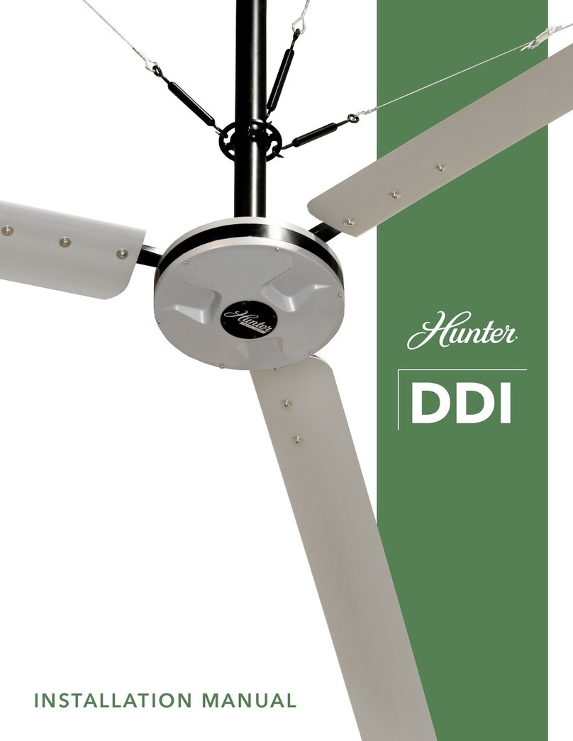
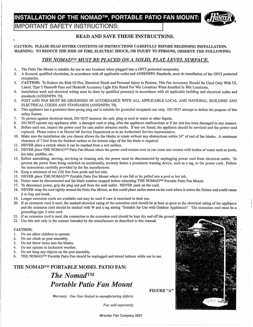
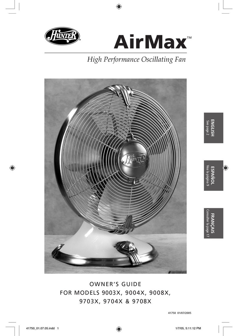
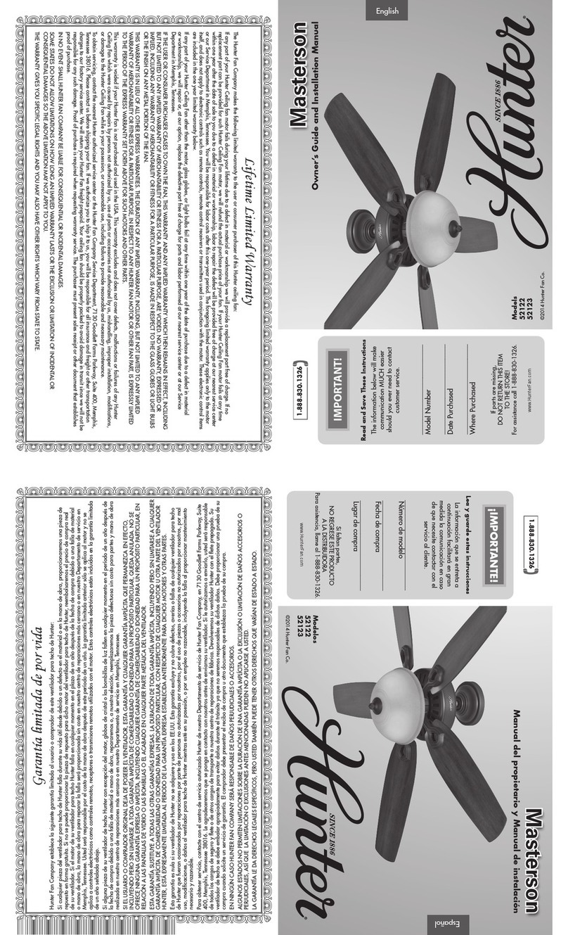
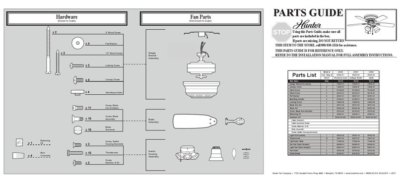
Hunter Hunter Ceiling fans User manual

1
44204-01 5/30/2007
Installation and Operation Manual
For Hunter Ceiling Fans
44203-01 05/30/2007

2
44204-01 05/30/2007

3
44204-01 5/30/2007
CONGRATULATIONS!
Your new Hunter ceiling fan is an ad-
dition to your home or ofce that will
provide comfort and performance
for many years. This manual gives
you complete instructions for install-
ing and operating your fan.
We are proud of our work. We ap-
preciate the opportunity to supply
you with the best ceiling fan avail-
able anywhere in the world.
Before installing your fan, record
the following information for your
records and warranty assistance.
Please refer to the carton and the
Hunter nameplate (located on top
outside fan motor housing) for the
proper information.
© 2007 Hunter Fan Co.
05/30/2007
Model Name ________________
Catalog No. _________________
Serial No.___________________
Date Purchased______________
Where Purchased ____________
___________________________
Attach Your Receipt
or a Copy of
Your Receipt Here

4
44204-01 05/30/2007
CONTENTS
Important Information ......................................................................................................................................... 5
Step 1 - Getting Ready....................................................................................................................................... 6
Step 2 - Assembling the Fan ............................................................................................................................. 7
Step 3 - Hanging the Fan ................................................................................................................................... 8
Step 4 - Wiring the Fan....................................................................................................................................... 9
Step 5 - Installing the Canopy ...........................................................................................................................11
Step 6 - Assembling Fan Blades ...................................................................................................................... 12
Step 7 - Completing Your Installation ............................................................................................................... 13
Operating Your Hunter Fan............................................................................................................................... 15
Cleaning and Maintenance............................................................................................................................... 16
Troubleshooting................................................................................................................................................ 17

5
44204-01 5/30/2007
IMPORTANT INFORMATION
not lock the circuit break-
ers in the off position, se-
curely fasten a prominent
warning device, such as a
tag, to the service panel.
• All wiring must be in accor-
dance with national and lo-
cal electrical codes. If you
are unfamiliar with wiring,
you should use a qualified
electrician.
• To reduce the risk of per-
sonal injury, do not bend
the blade attachment sys-
tem when installing, bal-
ancing, or cleaning the
fan. Never insert foreign
objects between rotating
fan blades.
• The fan blades cannot be
placed lower than 2,3m
from the floor.
DO YOU NEED HELP?
To install a ceiling fan, be sure you
can do the following:
• Locate ceiling joist or other
suitable support in ceiling.
• Identify and connect electrical
wires.
• Lift 16 kg.
If you need help installing the fan,
your Hunter fan dealer can direct
you to a licensed installer or elec-
trician.
WARNINGS
• To avoid possible electri-
cal shock, before installing
your fan, disconnect the
power by turning off the
circuit breakers to the out-
let box and associated wall
switch location. If you can-
CAUTIONS
• Read entire booklet care-
fully before beginning in-
stallation and save these
instructions.
• To reduce the risk of per-
sonal injury, attach the
fan directly to the support
structure of the building
according to these instruc-
tions, and use only the
hardware supplied.

6
44204-01 05/30/2007
GATHERING THE TOOLS
You need the following tools to in-
stall the fan:
• Standard screwdriver
• Phillips-head screwdriver
• Wrench or pliers
PREPARING THE FAN SITE
Reliable operation, efciency, and
maximum energy savings depend
upon proper placement and attach-
ment of the fan. This fan should be
installed on a previously installed
J-Hook or U-Hook.
STEP 1 - GETTING READY
CHECKING YOUR FAN PARTS
Carefully unpack your fan parts to
avoid damage. Check for shipping
damage. If one of the fan blades
is damaged, return all blades for
replacement.
Hint: If installing more than one fan,
keep the fan blades in sets, as
shipped.
Standard Mounting (Figure 1) hangs
from the ceiling by a connector
pipe (included), for ceilings 2.3 m
or higher. For ceilings higher than
2.3 m.
Figure 1 - Standard Mounting

7
44204-01 5/30/2007
STEP 2 - ASSEMBLING THE FAN
1. Feed the wires and the steel ca-
ble support from the fan through
the canopy and the pipe.
2. Screw pipe into fan assembly until
tight. IMPORTANT! Tighten pipe
setscrew as shown in Figure 2.
CAUTION
• The pipe adapter has a spe-
cial coating on the threads.
Do not remove this coat-
ing; the coating prevents
the pipe from unscrewing.
Once assembled, do not
remove the pipe.
WARNING
• Failure to complete the
steps above properly could
result in the fan falling.
Figure 2 - Assembling The Fan
Pipe Setscrew

8
44204-01 05/30/2007
STEP 3 - HANGING THE FAN
Hang fan from the previously in-
stalled J-Hook or U-Hook.
SECURING FAN TO SECOND-
ARY SUPPORT
1. Find the looped end of the braid-
ed cable and insert it through the
ceiling plate and one of the holes
in the outlet box into the ceiling.
2. Access the support brace in the
ceiling. You may not be able to
do this from below the ceiling
depending on your installation
site.
3. Drive a #10 x 38 mm (1-1/2")
wood screw and washer into the
side of the brace that holds the
outlet box. Leave 3 mm (1/8")
of space between the support
brace and the washer. Figure 3a - Installing the Wood Screw
into the Brace
Figure 3b - Hooking the Cable
Figure 3c - Tightening the Loop
4. Wrap the braided cable around
the support brace once creating
a complete circle.
5. Hook the looped end of the cable
over the wood screw so that the
braided cable lies between the
washer and the support brace.
See Figure 3b.
6. Tighten the loop and secure the
screw and washer all the way
down to the support brace. See
Figure 3c.
7. Coil up the excess cable. Return

9
44204-01 5/30/2007
STEP 4 - WIRING THE FAN
WARNING
• To avoid possible electrical
shock, before wiring fan,
disconnect power by turn-
ing off the circuit break-
ers both to the outlet box
and to its associated wall
switch location. If you can-
not lock the circuit break-
ers in the off position, se-
curely fasten a prominent
warning device, such as a
tag, to the service panel.
• All wiring must be in accor-
dance with national and lo-
cal electrical codes. If you
are unfamiliar with wiring,
you should use a qualified
WARNING
To reduce the risk of re, elec-
trical shock, or motor damage,
do not lift or carry the fan by
Disconnect the power by turning
off the circuit breakers to the outlet
box and associated wall switch
location.
CONNECTING FAN TO ELEC-
TRICAL SOURCE
Use Figure 4 for reference in mak-
ing the following electrical connec-
tions.
1. Connect the supply mains with a
wire nut.
2. Connect the earth wire and the
CAUTION
Be sure no bare wire or wire
strands are visible after mak-
ing connections.
green/yellow ground wire from
the hanger.
3. Connect the blue neutral wire to
the blue wire from the fan.
4. Connect the brown line wire to
the brown wire from the fan.
Note: Unless there is a sepa-
rate line for the light kit, connect
the black/white wire and brown
wire from the motor housing to
the brown wire from the ceil-
ing.

10
44204-01 05/30/2007
FIGURE 4 - WIRING DIAGRAM
Earth
Power�
Wires�
In �
Ceiling Blue
Brown
Blue
Black/White
1
2Connections:�
�
Brown
(Optional Line)�
Wall Switch Wire For �
Separate Control of Light Kit
Green/Yellow�
Wire from Hanger
3 Wires �
From Fan
(Note: Wall switch �
must be acceptable �
as a general-use�
switch.)
Connect Blk/Wht Wire from fan�
to Wall Switch Wire for separate�
control of light, or�
Connect Blk/Wht Wire from fan�
to Ceiling Brown Wire if there �
is no separate Wall Switch Wire�
for the light kit.
1
2

11
44204-01 5/30/2007
STEP 5 - INSTALLING THE CANOPY
Figure 5 - Assembling the Canopy
1. Slide the canopy to where the
top is within 2 mm of the ceiling.
The canopy should not touch the
ceiling or it will cause noise and
possible wobble.
2. Insert and tighten the #6-32
canopy screw to hold the canopy
in place. Refer to Figure 5.
Note: Screws and screw holes
are provided and may be used
to better level the canopy.
Canopy Screw
Canopy

12
44204-01 05/30/2007
Figure 6a - Opening Blade Iron
Locking Mechanism
Figure 6b - Assembling the Blade
STEP 6 - ASSEMBLING FAN BLADES
1. Open the locking mechanism as
shown in Figure 6a.
2. Align the holes in the blade with
the blade iron as shown in Fig-
ure 6b.
Locking
Mechanism
Locking
Mechanism
Closed
3. Close the locking mechanism se-
curely feeling it lock into place.

13
44204-01 5/30/2007
STEP 7 - COMPLETING YOUR INSTALLATION
Pull Chain Clip
Cap
Figure 7b
Figure 7a
1. Install 60 Watt A-19 bulbs.
2. Raise the shade until the
knobs go through the holes.
See Figure 7a.
3. Screw a cap shown in Figure
7a onto each knob. Tighten
securely.
Cap
Knob
4. Place a pull chain clip over
both caps. See Figure 7b.

14
44204-01 05/30/2007
Pull Chain
Breakaway Connector
Figure 7d
COMPLETING YOUR INSTALLATION
5. Remove the breakaway con-
nectors and extra chain from
the light and fan pull chains.
See Figure 7d.
6. Thread the light and fan pull
chains through the pull chain
clips. See Figure 7d.
7. Re-connect the breakaway
connectors and extra chain to
the light and fan pull chains.
See Figure 7d.

15
44204-01 5/30/2007
3. Ceiling fans work best by blowing
air downward (counterclockwise
blade rotation) in warm weather
to cool the room with a direct
breeze. In winter, having the
fan draw air upward (clockwise
blade rotation) will distribute the
warmer air trapped at the ceiling
around the room without causing
a draft. See Figure 8b.
OPERATING YOUR HUNTER FAN
Control switches are identied by
the following symbols:
Figure 8b - Air Flow Patterns
To change the direction of air
ow, turn the fan off and let it
come to a complete stop. Slide
the reversing switch on the fan to
the opposite position as shown in
Figure 8c. Restart fan.
4. If your fan wobbles when operat-
ing, use the enclosed balancing
kit and instructions to balance the
fan.
Figure 8c - Pull Chain and Reversing
Switch
1. Turn on electrical power to the
fan.
2. The pull chain controls power
to the fan. The chain has four
settings in sequence: High, Me-
dium, Low and Off.
• Pull the chain slowly to change
settings.
• Release slowly to prevent the
chain from recoiling into the
blades.
Figure 8a - Control Symbols
Fan Reversing
Light

16
44204-01 05/30/2007
CLEANING AND MAINTENANCE
Caring for blades: Wood finish
blades should be cleaned with a
furniture polishing cloth. Occasion-
ally, a light coat of furniture polish
may be applied for added protection
and beauty. Painted and high-gloss
blades may be cleaned in the same
manner as the fan nish.
If you need parts or service as-
sistance contact your Hunter Fan
retailer or visit our WEB site at:
http://www.hunterfan.com
Caring for nishes: For cleaning, a
soft brush or lint-free cloth should be
used to prevent scratching the n-
ish. A vacuum cleaner brush nozzle
can remove heavier dust. Surface
smudges or an accumulation of dirt
and dust can easily be removed by
using a mild detergent and a slightly
dampened cloth. An artistic agent
may be used, but never use abra-
sive cleaning agents as they will
damage the nish.

17
44204-01 5/30/2007
TROUBLESHOOTING
Nothing happens; fan does not
move.
Noisy operation.
1. Power turned off, fuse blown, or
circuit breaker tripped.
2. Loose wire connections or wrong
connections.
3. Motor reversing switch not en-
gaged.
4. Pull chain switch not “on.”
5. Shipping bumpers still in place.
1. Blade brackets screwed loosely to
motor.
2. Blade cracked.
PROBLEM PROBABLE CAUSE SOLUTION
1. Turn power on, replace fuse, or
reset breaker.
2a. Loosen canopy, check all connec-
tions according to STEP 4 - WIRING
THE FAN (turn power off before
checking).
3. Push switch rmly up or down.
4. Pull switch chain.
5. Remove shipping bumpers.
1. Tighten screws until snug.
2. Replace all blades.

18
44204-01 05/30/2007
PROBLEM PROBABLE CAUSE SOLUTION
Noisy operation (continued).
Excessive wobbling.
Note: When switching from medium to
low speed, you may notice some fan
wobble. When the fan stabilizes at low
speed, wobble will disappear.
4. Using non-approved speed con-
trol.
5. Glass screwed loosely to xture.
6. Switch housing is loose.
1. Unbalanced blades.
2. Loose blades or blade irons.
3. Fannotsecureonhangerassembly.
4. Fan hanger ball not seated in
4. Change to approved speed con-
trol.
5. Hand-tighten the light fixture
screws. Ensure that rubber noise
isolators are installed.
6. Check and tighten screws to the
switch housing mounting plate
and to the upper and lower switch
housing.
1. Use balancing kit included with
fan.
2. Tighten all screws.
3. Turn power off, support fan very
carefully, loosen canopy and hang
correctly.
4. Turn power off, support the fan
very carefully, and check that the
hanger ball is properly seated.
If you have tried these troubleshooting solutions and still have trouble, visit our Web site at http://www.hunterfan.
Other manuals for Hunter Ceiling fans
23
Table of contents
Other Hunter Fan manuals

Hunter
Hunter 82040 User manual

Hunter
Hunter 18865 Manual

Hunter
Hunter 28463 Manual

Hunter
Hunter 43044-01 User manual

Hunter
Hunter 82022 User manual

Hunter
Hunter Crescent Falls User manual

Hunter
Hunter 25692 User manual

Hunter
Hunter 41949-01 User manual

Hunter
Hunter 50310 User manual

Hunter
Hunter 80707 User manual

Hunter
Hunter Anorak User manual

Hunter
Hunter 21705 Instruction Manual

Hunter
Hunter 51264 User manual

Hunter
Hunter 27196 User manual

Hunter
Hunter Interface 51353 User manual

Hunter
Hunter 20168 Instruction manual

Hunter
Hunter Gilrock User manual

Hunter
Hunter 28480 Manual

Hunter
Hunter 42653-01 Instruction manual

Hunter
Hunter Kensie 50642 User manual