manuals.online logo
Brands
  1. Home
  2. •
  3. Brands
  4. •
  5. Hunter
  6. •
  7. Thermostat
  8. •
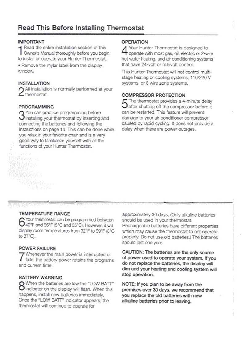
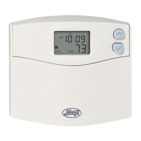
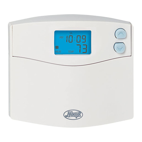
  9. Hunter 44050 User manual

Hunter 44050 User manual

This manual suits for next models

1

Other Hunter Thermostat manuals

Hunter 44428 Original instructions

Hunter

Hunter 44428 Original instructions

Hunter Set & Save 47350A User manual

Hunter

Hunter Set & Save 47350A User manual

Hunter 44300 User manual

Hunter

Hunter 44300 User manual

Hunter 44272 Assembly instructions

Hunter

Hunter 44272 Assembly instructions

Hunter 44300 User manual

Hunter

Hunter 44300 User manual

Hunter 44905 Assembly instructions

Hunter

Hunter 44905 Assembly instructions

Hunter Set & Save 47300A User manual

Hunter

Hunter Set & Save 47300A User manual

Hunter 44273 User manual

Hunter

Hunter 44273 User manual

Hunter F42213 User manual

Hunter

Hunter F42213 User manual

Hunter 43058 User manual

Hunter

Hunter 43058 User manual

Hunter 44905 User manual

Hunter

Hunter 44905 User manual
Hunter 44660 User guide

Hunter

Hunter 44660 User guide

Hunter Set & Save 44377W User manual

Hunter

Hunter Set & Save 44377W User manual

Hunter 44260 User manual

Hunter

Hunter 44260 User manual

Hunter Auto Temp 44402 002 User manual

Hunter

Hunter Auto Temp 44402 002 User manual

Hunter 44860 User manual

Hunter

Hunter 44860 User manual

Hunter 44127 User manual

Hunter

Hunter 44127 User manual

Hunter 40020 User manual

Hunter

Hunter 40020 User manual

Hunter Set & Save 47110A User manual

Hunter

Hunter Set & Save 47110A User manual
Hunter 42177 User manual

Hunter

Hunter 42177 User manual

Hunter 44200 User manual

Hunter

Hunter 44200 User manual

Hunter 44378 User manual

Hunter

Hunter 44378 User manual

Hunter 44668 User manual

Hunter

Hunter 44668 User manual

Hunter 42999 User manual

Hunter

Hunter 42999 User manual

Popular Thermostat manuals by other brands

Full Gauge TIC-17C product manual

Full Gauge

Full Gauge TIC-17C product manual

Imit Chronomix S manual

Imit

Imit Chronomix S manual

ChiliTec ST-35 ana instruction manual

ChiliTec

ChiliTec ST-35 ana instruction manual

Salus VS05 Installer's/user's manual

Salus

Salus VS05 Installer's/user's manual

Azel D-500 user guide

Azel

Azel D-500 user guide

Honeywell Chronotherm III owner's manual

Honeywell

Honeywell Chronotherm III owner's manual

Charmeg MP-R user manual

Charmeg

Charmeg MP-R user manual

dixell WING XW40LS Installing and operating instructions

dixell

dixell WING XW40LS Installing and operating instructions

Network Thermostat NetX X7C-WIFI Installation and programming manual

Network Thermostat

Network Thermostat NetX X7C-WIFI Installation and programming manual

Radio Thermostat CT80 Operation guide

Radio Thermostat

Radio Thermostat CT80 Operation guide

HAI Omnistat RC-120 installation manual

HAI

HAI Omnistat RC-120 installation manual

Lennox iComfort E30 Installation and setup guide

Lennox

Lennox iComfort E30 Installation and setup guide

Lux Products PSD011Ba Installation and operating instructions

Lux Products

Lux Products PSD011Ba Installation and operating instructions

Computherm Q20 operating instructions

Computherm

Computherm Q20 operating instructions

Heatmiser neoStat user manual

Heatmiser

Heatmiser neoStat user manual

Mars HEAT CONTROLLER IR Wireless Thermostat user manual

Mars

Mars HEAT CONTROLLER IR Wireless Thermostat user manual

LUX LP0511D user manual

LUX

LUX LP0511D user manual

Saswell SAS920XWHB-7-S-RF User manual and warranty card

Saswell

Saswell SAS920XWHB-7-S-RF User manual and warranty card

manuals.online logo
manuals.online logoBrands
  • About & Mission
  • Contact us
  • Privacy Policy
  • Terms and Conditions

Copyright 2025 Manuals.Online. All Rights Reserved.

Owner’s Manual
File: 511/41251/book p. 1-15 Created: 5-28-98 r
Folder: 511/hunter/for 41251 Alt: 6-24-98 db
Prints black
42999, 44050
SINCE 1 8 8 6
®
511/41251/book p. 1-15 2/8/01 2:24 PM Page 1
Other Quality Products from Hunter
Fans
Air Purifiers Hu idifiers
511/41251/book p. 1-15 2/8/01 2:24 PM Page 2
Installation
Operation
Table Of Contents
Features 6
Re ove Old Ther ostat 8
Labeling Wires 10
Connecting Wires and Mounting Ther ostat 14
Syste Selector Switches 14
Start-Up 16
Reviewing Current Te perature Setting 16
Setting New Te perature 17
Filter Monitor 18
Resetting Filter Counter To Zero 19
Te perature Span 19
Backlighting 19
Trouble Shooting 20
Typical Wiring Diagra s 22
We are pleased you have selected one of our broad line of ho e co fort products. Our
products are anufactured to high quality standards and are designed for years of service.
We hope you will be satisfied and thank you for buying a Hunter product.
511/41251/book p. 1-15 2/8/01 2:24 PM Page 3
Read This Before Installing Thermostat
IMPORTANT
1
Read the entire installation section of this
Owner’s Manual thoroughly before you begin
to install or operate your Hunter Ther ostat.
• Re ove the ylar label fro the display
window.
INSTALLATION
2
All installation is nor ally perfor ed at your
ther ostat.
PROGRAMMING
3
You can practice progra ing before
installing your ther ostat by inserting and
connecting the batteries and following the
instructions on page 14. This can be done while
you relax in your favorite chair and is a very
good way to fa iliarize yourself with all the
functions of your Hunter Ther ostat.
OPERATION
4
Your Hunter Ther ostat is designed to
operate with ost gas, oil, electric or 2-wire
hot water heating, and air conditioning syste s
that have 24-volt or illivolt control.
This Hunter Ther ostat will not control ulti-
stage heating or cooling syste s, 110/220 V
syste s, or 3 wire zone syste s.
COMPRESSOR PROTECTION
5
The ther ostat provides a 4- inute delay
after shutting off the co pressor before it
can be restarted. This feature will prevent
da age to your air conditioner co pressor
caused by rapid cycling. It does not provide a
delay when there are power outages.
511/41251/book p. 1-15 2/8/01 2:24 PM Page 4
TEMPERAT RE RANGE
6
Your ther ostat can be progra ed between
40°F and 95°F (5°C and 35°C). However, it will
display roo te peratures fro 32°F to 99°F (0°C
to 37°C).
POWER FAIL RE
7
Whenever the ain power is interrupted or
fails, the battery power retains the progra s
and current ti e.
BATTERY WARNING
8
When the batteries are low the “LOW BATT”
indicator on the display will flash. When this
happens, install new batteries i ediately.
Once the “LOW BATT” indicator appears, the
ther ostat will continue to operate for
approxi ately 30 days. (Only alkaline batteries
should be used in your ther ostat.
Rechargeable batteries have different properties
which ay cause the ther ostat to not operate
properly. Do not use old batteries.) The batteries
should last one year.
CA TION: The batteries are the only source
of power used to operate your system. If you
do not replace the batteries, the display will
dim and your heating and cooling system will
stop operation.
NOTE: If you plan to be away from the
premises over 30 days, we recommend that
you replace the old batteries with new
alkaline batteries prior to leaving.
511/41251/book p. 1-15 2/8/01 2:24 PM Page 5
FILTER
HEAT OFF COOL A TO FAN RESET
Features (Model 42999)
■Function
Switch
For turning
on heating
and cooling
syste .
■Fan ON
and
AUTO
Selector
Switch.
■Reset Button
For resetting
ther ostat.
■Easy access battery co part ent.
■Easy-To-Read
Digital Display
Liquid crystal
display shows
roo
te perature, set
te perature,
filter indicator,
low battery
indicator, heat
and cool syste
indicator.
■Unique Filter
Monitor
Auto atically
re inds you to
clean or
replace your
heating and air
conditioning
filters.
■For raising
te perature.
■For lowering
te perature.
69
C
TEMP
SET TEMP
FILTER
LO BAT
HOLD HEAT COOL
■To reset filter
counter back
to zero.
6-7
511/41251/book p. 1-15 2/8/01 2:24 PM Page 6
Features (Model 44050)
■Function
Switch
For turning
on heating
and cooling
syste .
■Fan ON
and AUTO
Selector
Switch.
■Reset Button
For resetting
ther ostat.
■Easy access battery co part ent.
■Easy-To-Read
Digital Display
Liquid crystal
display shows
roo
te perature, set
te perature,
filter indicator,
low battery
indicator, heat
and cool syste
indicator.
■Unique Filter
Monitor
Auto atically
re inds you to
clean or
replace your
heating and air
conditioning
filters.
■For raising
te perature.
■For lowering
te perature.
69
C
TEMP
SET TEMP
FILTER
LO BAT
HOLD HEAT COOL
■Display
backlight for
viewing in
the dark.
■To reset filter
counter back
to zero.
FILTER
LIGHT
HEAT OFF COOL A TO FAN RESET
511/41251/book p. 1-15 2/8/01 2:24 PM Page 7
8-9
Installation
This ther ostat co es with two #8 slotted screws and two wall anchors for ounting. To
install your unit, you should have the following tools and aterials.
■Slotted screwdriver ■Electric drill and 3/16" bit
■Ha er ■Two 1.5V (AA) Size Alkaline batteries
CA TION: Do not remove any wiring from existing thermostat before reading the
instructions carefully. Wires must be labeled prior to removal.
■IMPORTANT! Turn off the power to the furnace at the ain power panel or at the furnace.
■Re ove existing ther ostat cover and ther ostat. See Figure 1. So e ther ostats will have
screws or other locking devices that ust first be re oved. Once wall ounting plate is
exposed, look for wires.
■If wires are not visible, they ay be connected to the back of the wallplate. Again, look for
screws, tabs, etc. So e odels have doors that open to expose wires and ounting screws.
(See Figure 1).
What You Need
Remove Old Thermostat
511/41251/book p. 1-15 2/8/01 2:24 PM Page 8
Wall Mounting Plate Ther ostat Cover
TYPICAL HOME THERMOSTATS
FIG RE 1
511/41251/book p. 1-15 2/8/01 2:24 PM Page 9
10-11
Installation
■Each wire co ing fro the wall to the existing ther ostat is connected to a ter inal point on
that ther ostat. Each of these ter inal points is usually arked with a code letter as shown in
Table A on page 9.
■The nu ber of wires in your syste can be as few as two (for heat only syste s), as any as
eight, or any nu ber in between. If you follow the labeling procedures correctly, you do not
have to be concerned about how any wires there are.
■There is often no ter inal arking on the existing ther ostat of two wire, heat only syste s.
Do not worry, just connect either of the wires to the RH ter inal, then connect the other wire
to the W ter inal to co plete the circuit.
■IMPORTANT! BEFORE DISCONNECTING ANY WIRES, APPLY THE SELF-ADHESIVE LABELS
PROVIDED TO THE WIRE AS SHOWN IN TABLE A ON PAGE 11. (For exa ple, attach the
label arked W to the wire which goes to the W or H ter inal on your existing ther ostat.)
IGNORE THE COLOR OF THE WIRES since these do not always co ply with the standard.
■After labeling wires, disconnect the fro the existing
ther ostat ter inals.
■Re ove existing wallplate. To ake sure wires do not fall back
into wall opening, you ay want to tape the to the wall.
■If hole in wall is larger than necessary for wires, seal this hole so
that no hot or cold air can enter the back of the ther ostat
fro the wall. This air could cause a false ther ostat reading.
Label Wires
WGYRH
RC
511/41251/book p. 1-15 2/8/01 2:24 PM Page 10