Hunter Fan User manual

1
41343-01 6/12/2002
®
41343-01 7/1/2002
Installation and Operation Manual
For Hunter Ceiling Fans
41343-01 7/1/2002

2
®
41343-01 7/1/2002

3
41343-01 6/12/2002
®
41343-01 7/1/2002
CONGRATULATIONS!
Your new Hunter ceiling fan is an
addition to your home or office that
will provide comfort and perfor-
mance for many years. This manual
gives you complete instructions for
installing and operating your fan.
We are proud of our work. We ap-
preciate the opportunity to supply
you with the best ceiling fan avail-
able anywhere in the world.
Before installing your fan, record the
following information for your
records and warranty assistance.
Please refer to the carton and the
Hunter nameplate (located on top
outside fan motor housing) for the
proper information.
© 2002 Hunter Fan Co.
7/1/2002
Model Name __________________
Catalog No. ___________________
Serial No. _____________________
Date Purchased ________________
WherePurchased ______________
____________________________
Attach Your Receipt
or a Copy of
Your Receipt Here

4
®
41343-01 7/1/2002
CONTENTS
IMPORTANT INFORMATION.................................................................................................................................5
STEP 1 - GETTING READY ...................................................................................................................................6
STEP 2 - INSTALLING THE CEILING PLATE ...........................................................................................................8
STEP 3 - ASSEMBLING THE FAN........................................................................................................................ 10
STEP 4 - WIRING THE FAN ................................................................................................................................ 12
STEP 5 - HANGING THE FAN............................................................................................................................. 14
STEP 6 - ASSEMBLING FAN BLADES.................................................................................................................. 15
STEP 7 - ATTACHING THE SWITCH HOUSING ................................................................................................... 17
STEP 8 - INSTALLING LIGHT FIXTURE................................................................................................................. 20
OPERATING YOUR HUNTER FAN ....................................................................................................................... 25
CLEANING AND MAINTENANCE ...................................................................................................................... 26
TROUBLESHOOTING.......................................................................................................................................... 27

5
41343-01 6/12/2002
®
41343-01 7/1/2002
IMPORTANT INFORMATION
not lock the circuit break-
ers in the off position, se-
curely fasten a prominent
warning device, such as a
tag, to the service panel.
• All wiring must be in ac-
cordance with national and
local electrical codes and
ANSI/NFPA 70. Ifyou are un-
familiar with wiring, you
should use a qualified elec-
trician.
• To reduce the risk of per-
sonal injury, do not bend
the blade attachment sys-
tem when installing, bal-
ancing, or cleaning the fan.
Never insert foreign ob-
jects between rotating fan
blades.
DO YOU NEED HELP?
To install a ceiling fan, be sure you
can do the following:
• Locate ceiling joist or other suit-
able support in ceiling.
• Drill holes for and install wood
screws.
• Identify and connect electrical
wires.
• Lift 40 pounds.
If you need help installing the fan,
yourHunterfandealercan directyou
to a licensed installer or electrician.
• To reduce the risk of fire,
electrical shock, or motor
damage, do not use a solid-
state speed control with
this fan. Use only Hunter
speed controls.
WARNINGS
• To avoid possible electrical
shock, before installing
your fan, disconnect the
power by turning off the
circuit breakers to the out-
let box and associated wall
switch location. If you can-
CAUTIONS
• Read entire booklet care-
fully before beginning in-
stallation and save these
instructions.
• To reduce the risk of per-
sonal injury, attach the fan
directly to the support
structure of the building
according to these instruc-
tions, and use only the
hardware supplied.

6
®
41343-01 7/1/2002
GATHERING THETOOLS
You will need the following tools for
installing the fan:
• Electric drill with 9/64" bit
• Standard screwdriver
• Phillips-head screwdriver
• Wrench or pliers
OPTIONALACCESSORIES
ConsiderusingHunter’soptionalaccesso-
ries,includingawall-mountedorremote
speedcontrol.Toinstall andusetheac-
cessories,followtheinstructionsincluded
witheachproduct.
Forquietandoptimumperformanceof
yourHunterfan,useonlyHunterspeed
controls.
STEP 1 - GETTING READY
PREPARING THE FAN SITE
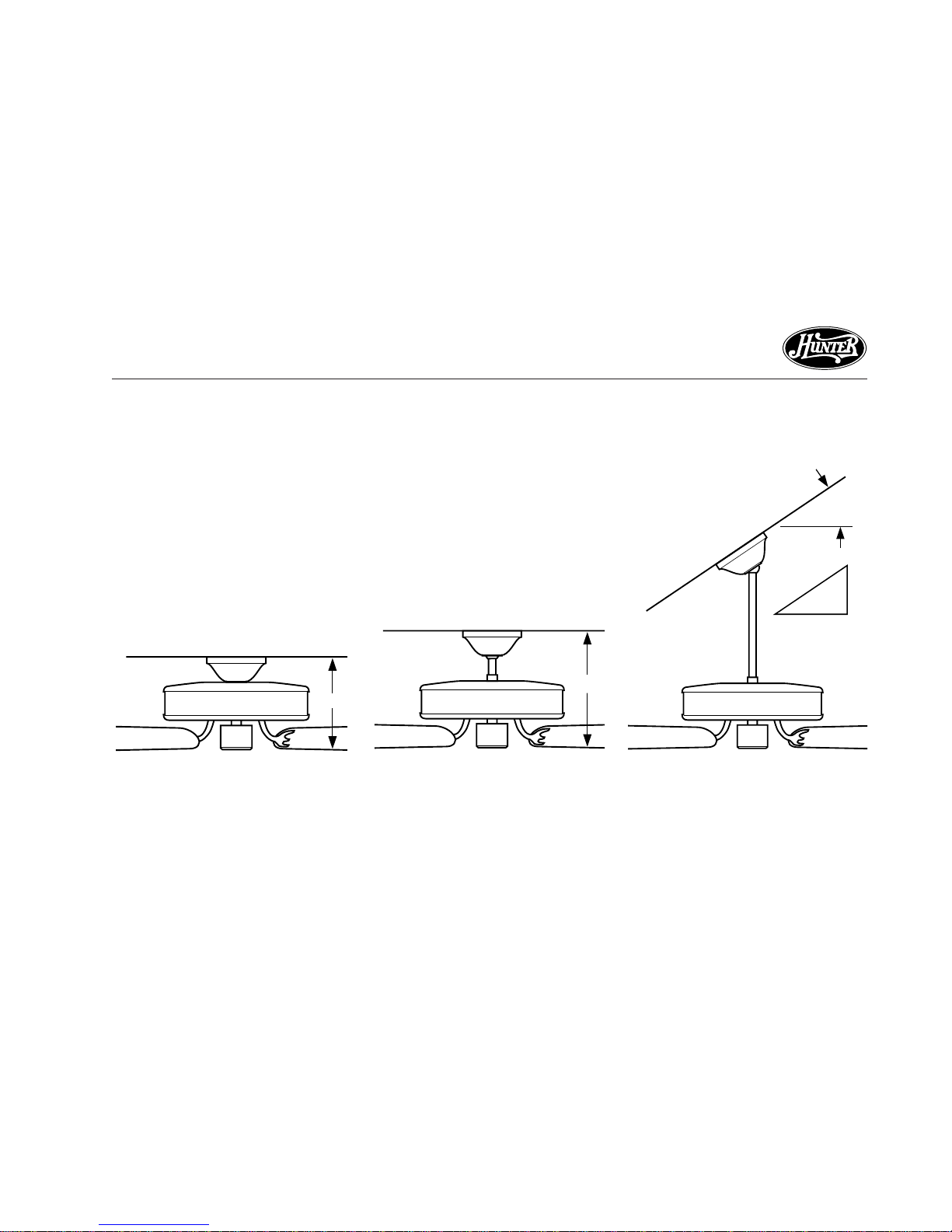
Thelocation of a ceiling fan andhow
the fan is attached to the building
structure are essential for reliable
operation, maximum efficiency, and
energy savings. For this reason, we
have included a separate booklet —
“Guide to Choosing and Preparing
a Ceiling Fan Site” — to help you
select the best location for your fan.
The booklet also provides informa-
tion to ensure your fan support and
electricoutlet box meet UL-approved
safety codes for ceiling fans.
The instructions in this installation
manual assume that you have used
“Guide to Choosing and Preparing
a Ceiling Fan Site” to pick the fan
locationand make certain theproper
fan support and outlet box are in-
stalled.
CHECKING YOUR FAN PARTS
Carefully unpack your fan to avoid
damage to the fan parts. Check for
any shipping damage to the motor
orfan blades. Ifone of the fanblades
wasdamagedinshipment,return all
the blades for replacement.
Hint: If you are installing more than
one fan, keep the fan blades
in sets, as they were shipped.
If any parts are missing or damaged,
contact your Hunter dealer or call
Hunter Parts Department at
901-248-2222.

7
41343-01 6/12/2002
®
41343-01 7/1/2002
INSTALLER’S CHOICE®
This patented 3-position mounting
systemprovidesyou maximuminstal-
lation flexibility and ease. You can
installyour Hunterfan in oneof three
ways. The steps in this manual in-
cludespecific instructions for the fan
mountingmethod ofyour choice.For
a ceiling 8 feet or higher, standard
mounting is recommended.
Flush Mounting (Figure1a)fits close
to the ceiling, for low ceilings less
than 8 feet high.
Standard Mounting (Figure 1b)
hangs from the ceiling by a connec-
torpipe (included), for ceilings 8 feet
or higher. For ceilings higher than
eight feet, you can purchase Hunter
extension rods. All Hunter fans use
sturdy 3/4" diameter pipe to assure
stability and wobble-free perfor-
mance.
Angle Mounting (Figure 1c) hangs
from a vaulted or angled ceiling.
Figure 1c - Angle Mounting
Figure 1b - Standard Mounting
Figure 1a - Flush Mounting
10"
12"
34°Max
Pitch
12
8

8
®
41343-01 7/1/2002
STEP 2 - INSTALLING THE CEILING PLATE
4. Align the slotted holes in the ceil-
ing plate with the pilot holes in
thewoodsupportstructure. Note:
Theisolation pads should beflush
against the ceiling.
1. Drill twopilot holes intothe wood
support structure through the
outermost holes on the outlet
box. The pilot holes should be
9/64" in diameter.
2. Thread the lead wires from the
outletbox throughthe holein the
middle of the ceiling plate.
3. Your fan comes with two neo-
prene noise isolators. Position the
isolatorsbetween theceiling plate
andceilingbyinserting the raised
areas on each isolator into the
holes in the ceiling plate. Refer to
Figure 2a.
Figure 2a - Adding Isolators to Ceiling
Plate
Figure 2b - Correct Position of Ceiling
Plate for Angle Mounting
Isolators
Ceiling
Plate
ForAngle Mounting Only:Be sure
to orient the ceiling plate so that
the two hooks point up towards
the ceiling peak as shown in Fig-
ure 2b. Note: You will use the
hooks to support the fan during
STEP 4 - WIRING THE FAN.

9
41343-01 6/12/2002
®
41343-01 7/1/2002
Figure 2c - Attaching Ceiling Plate to 2
x 4 Brace
2 x 4 Brace
Ceiling Joist
Ceiling
Outlet Box
Ceiling
Plate
Flat
Washer 3" Wood
Screw
5. Placea flat washer on each of the
two 3" screws and pass the
screws through the slotted holes
in the ceiling plate as shown in
Figure 2c.
6. Tighten the screwsinto the 9/64"
pilot holes; do not use lubricants
on the screws. Do not over-
tighten.

10
®
41343-01 7/1/2002
STEP 3 - ASSEMBLING THE FAN
Use the Step 3 instructions for the
type of mounting you have selected:
standard, angle, or flush.
STANDARDANDANGLEMOUNTING
For Standard 8-foot Ceilings and
Higher
1. Insert the pipe through the
canopy as shown in Figure 3a.
Feed wires from the fan through
the pipe.
2. Screw pipe into fan assembly un-
til tight. IMPORTANT! Tighten
pipe setscrew as shown in Figure
3a.
CAUTION
The pipe has a special coating
on the threads. Do not remove
this coating; the coating pre-
vents the pipe from unscrew-
ing. Once assembled, do not
remove the pipe.
FLUSHMOUNTING
For Low Ceilings
1. Fit the canopy over the motor
hanger adapter as shown in Fig-
ure 3b. Make sure the canopy fits
Figure 3a - Inserting Pipe through
Canopy
Pipe
Canopy
Pipe
Setscrew
Figure 3b - Placing Canopy and
Washer Over Adapter
Assembly
Washer
Canopy
Adapter
Top of Fan
snugly against the fan assembly
withnospace betweenthepieces.
2. You will find a large assembly
washer included with the fan.
Placethe washer overthe adapter
andcanopyas showninFigure 3b.

11
41343-01 6/12/2002
®
41343-01 7/1/2002
Assembly
Washer
Adapter Threaded
Hole
Figure 3d - Attaching Canopy to Fan
Assembly
Figure 3c - Positioning Assembly
Washer Slots over Threaded Holes
3. Position theslots in the assem-
bly washer over the threaded
holes in the adapter as shown
in Figure 3c.
4. Attach the canopy tightly to the
fan assembly with three #8-32
assemblyscrewsand lockwashers
as shown in Figure 3d.
Assembly Screw
and Lockwasher

12
®
41343-01 7/1/2002
STEP 4 - WIRING THE FAN
1. Disconnect the power by turning
offthe circuit breakerstothe out-
letbox and associated wallswitch
location.
2. Tilt and hang the assembled fan
from the ceiling plate hooks. Slip
tworectangularcanopy slots over
ceiling plate hooks as shown in
Figures 4a and 4b.
Note: To hang the fan you must
tilt the canopy to an almost verti-
cal position so the canopy slots
come down over the ceiling plate
hooks.
3. Youcanuse eitherone ortwo wall
switchesto control the fanand/or
lights separately. Use connection
1 on page 13 to
• control the light with a wall
switch and the fan with a
chain pull (one wall switch re-
quired)
• control the light with a chain
pull and the fan with a wall
switch (one wall switch re-
quired)
• control the light with one wall
switch and the fan with an-
other (two wall switches re-
quired)
Use connection 2 on page 13 if
there is no separate wall switch
power wire for the light fixture.
Note: Wallswitches notincluded.
Figure 4b - Assembled Fan Hanging
from Ceiling Plate Hooks
Ceiling
Plate
Figure 4a - Attaching Slots on Canopy
to Ceiling Plate Hooks

13
41343-01 6/12/2002
®
41343-01 7/1/2002
Bare or Green
Green
Approved
Connectors
Power
Wires
In
Ceiling White
White
Black
Black/White
1
2Connections:
Black
Wall Switch Wire For
Separate Control of Light Fixture
Ceiling
Plate
Outlet Box
2 x 4 Brace
Green Ground
Wire from Hanger
Pipe (not present
with flush mounting
option) 3 Wires
From Fan
(Note: Wall switch
must be acceptable
as a general-use
switch.)
Connect Blk/Wht Wire from fan
to Wall Switch Wire for separate
control of light fixture, or
Connect Blk/Wht Wire from fan
to Ceiling Black Wire if there
is no separate Wall Switch Wire
for the light fixture.
1
2
4. Connectthewires asshowninFig-
ure 4c.To connectthe wires,twist
the bare metal leads together.
Place a wire nut over the inter-
twined length of wire and twist
clockwise until tight as shown.
CAUTION
Be sure no bare wire or wire
strands are visible after mak-
ing connections.
5. Separate the connected wires by
placingthe greenandwhite wires
on one side of the outlet box and
the black and the black/white
wires on the other side of the
outlet box.
6. Turnthe connectorsupward.Push
the wires gently into the outlet
box.
Figure 4c - Wiring Diagram

14
®
41343-01 7/1/2002
STEP 5 - HANGING THE FAN
Figure 5a - Attaching Canopy to
Ceiling Plate
Figure 5b - Canopy Tabs and Grooves
in Hanger Ball
Sub-steps1and2applytoFlush,Stan-
dard,and Angle mounting. Sub-step
3 applies to Standard and Angle
mountingonly.
1. Swing the fan up so as to align
the canopy screw holes with the
mounting holes on the ceiling
plate. Refer to Figure 5a.
2. Installand tightenthe two#10-32
x1/2" mounting screws.
3. For Standard and Angle Mount-
ing only: In addition to sub-steps
1 and 2, lift the fan housing to-
wards the ceiling and rotate the
fanuntil eachcanopy tabengages
a groove in the hanger ball as
shown in Figure 5b.
Note: If the tabs are already en-
gaged, do not rotate.
WARNING
Failure to complete sub-steps
1 through 3 could cause fan to
fall. (Sub-step 3 not applicable
for flush mounting.)
Ceiling
Plate
Canopy
Groove in
Hanger
Ball
Canopy
Tab
Groove in
Hanger Ball

15
41343-01 6/12/2002
®
41343-01 7/1/2002
Figure 6a - Inserting Grommet into
Fan Blade Figure 6b - Attaching Fan Blade to
Blade Iron
Figure 6c - Attaching Fan Blade to
Blade Iron using Decorative Medallion
well as a blade iron. Insert the
assembly screws into the blade
iron, through the blade and into
the medallion, with the blade
sandwiched between the blade
iron and medallion as shown in
Figure 6c.
Hunter fans use several styles of fan
blade irons (brackets that hold the
blade to the fan).
1. Yourfan mayinclude blade grom-
mets. If your fan has grommets,
insertthem byhand intotheholes
as shown in Figure 6a.
2. Attach each blade to blade iron
usingthreebladeassembly screws
asshown in Figure 6b. Some fans
feature a decorative medallion as
STEP 6 - ASSEMBLING FAN BLADES If you used grommets, the blades
may appear slightly loose after
screws are tightened. This is nor-
mal.
3. Remove the blade mounting
screws and rubber shipping
bumpersfromthe motor.
Grommet
Fan
Blade
Medallion
Blade
Iron
continued

16
®
41343-01 7/1/2002
4. For each blade, insert one blade
mountingscrewthroughtheblade
iron as shown in Figure 6d, and
attachlightly to thefan. Insert the
second blade mounting screw,
thensecurelytighten bothmount-
ing screws.
Figure 6d - Attaching Blade Irons to
Hub of Fan Assembly

17
41343-01 6/12/2002
®
41343-01 7/1/2002
STEP 7 - ATTACHING THE SWITCH HOUSING
Figure 7a - Attaching Upper Switch
Housing to Switch Housing Mounting
Plate
Housing
Assembly
Screw
Switch
Housing
Mounting
Plate Upper Plug
Connector
Upper
Switch
Housing Figure 7b - Mounting the Upper
Switch Housing
CAUTION
Make sure the upper switch
housing is securely attached to
the switch housing mounting
plate. Failure to properly at-
tach and tighten all three hous-
ing assembly screws could re-
sult in the switch housing and
light fixture falling.
Theswitchhousing ismade upoftwo
sections: the upper switch housing,
and the lower switch housing.
ATTACHING THE UPPER SWITCH
HOUSING
1. Partially install two #6-32 x 3/8"
housing assembly screws into the
switchhousing mounting plate as
shown in Figure 7a.
2. Feed the upper plug connector
through thecenter openingof the
upper switch housing. See Figure
7a.
3. Align the keyhole slots in the up-
perswitch housingwith the hous-
ing assembly screws installed in
sub-step 1.
4. Turn the upper switch housing
counterclockwise until the hous-
ing assembly screws are firmly
situated in the narrow end of the
keyhole slots as shown in Figure
7b. Install the one remaining #6-
32x 3/8" housingassembly screw
into the third hole in the upper
switch housing. Tighten all three
screws firmly.
continued

18
®
41343-01 7/1/2002
Table 7-1
Fan with no light
fixtureincluded See Figure 7c
Fan with single-
globelight fixture See Figure 7c
included
Fan with multi-
lightlight fixture See Figure 7d
included
Fan with integra-
ted single globe See Figure 7e
If your fan has a lower switch hous-
ing as shown in Figure 7c, and you
ARE installing an accessory light kit
or single-globe light fixture included
with your fan, go directly to STEP
8 - INSTALLING LIGHT FIXTURE.
Figure 7c
Figure 7d
ATTACHING THE LOWER SWITCH
HOUSING
Your hunter fan includes one of two
lower switch housings. Both lower
switchhousings are showninFigures
7c, 7d and 7e. The type of lower
switchhousing you have depends on
whether your fan includes a light fix-
ture, and if so, what type of light fix-
ture it is. Use table 7-1 to assist you.
Figure 7e
continued

19
41343-01 6/12/2002
®
41343-01 7/1/2002
If your fan has a lower switch hous-
ing as shown in Figure 7c and you
ARE NOT installing a light fixture, or
if your fan has a lower switch hous-
ingas shownin Figure7d or 7f, com-
plete the following steps:
1. Connect the upper plug connec-
tor from the motor to the lower
plug connector in the lower
switchhousing assembly. See Fig-
ure7f.
Note: Both plug connectors are
polarizedand willonly fittogether
one way. Make sure that both
connectors are properly aligned
beforeconnecting them together.
Incorrect connection could cause
improper operation and damage
to the product.
Figure 7f - Plug Connection and Lower
Switch Housing Installation
Upper
Switch
Housing
Upper Plug
Connector
Lower Plug
Connector
Lower
Switch
Housing
Housing
Assembly
Screw
2. Place the lower switch housing
assembly over the upper switch
housing. Align the side screw
holes in the upper and lower
switchhousings. Attachthe lower
switch housing to the upper
switch housing with three #6-32
x 3/8" housing assembly screws.
See Figure 7f.
Note: Ifyour fan doesnot include
a light fixture, you may purchase
an accessory light kit separately.
See STEP 8 - INSTALLING LIGHT
FIXTURE.

20
®
41343-01 7/1/2002
STEP 8 - INSTALLING LIGHT FIXTURE
Figure 8a - Removing Plug Button and
Switch Housing Cap
Lower
Switch
Housing
Plug Button
Your fan may include a light fixture.
Information for wiring and installing
all included Hunter light fixtures fol-
lows.
Note:If youpurchased a fanwithout
a light fixture, you may purchase an
accessorylight kit separately. For best
performance and beauty, use only
Hunter-brand light kits, Type A-Z.
Hunterlight kitsare designed,tested,
and UL approved for all Hunter fans,
and are available at most Hunter
dealers. To install the light kit, follow
theinstructions included withthe kit.
Ifyou are notinstalling a light fixture,
turn to OPERATING YOUR HUNTER
FAN for additional instructions.
Switch
Housing
Cap
WARNING
• To avoid possible electrical
shock, before installing
light fixtures, disconnect
power by turning off the
circuit breakers both to the
outlet box and to its asso-
ciated wall switch location.
If you cannot lock the cir-
cuit breakers in the off po-
sition, securely fasten a
prominent warning device,
such as a tag, to the service
panel.
• Connect house wiring to
the fan before attaching
the light fixture to the fan.
• All wiring must be in accor-
dance with national and lo-
calelectrical codesandANSI/
NFPA 70. If you are unfamil-
iar with wiring, you should
use a qualified electrician.
Table of contents
Other Hunter Ventilation Hood manuals
Popular Ventilation Hood manuals by other brands

Kleenmaid
Kleenmaid Rangehood RH10 Instructions for use and warranty details

Cata
Cata PROFESSIONAL 750 Operating and installation instructions

Omega
Omega ORW6XA Instructions for the use and care and installation

Remus
Remus 117782 320018 Installation instruction

NuTone
NuTone 463004 Specification sheet

Brandt
Brandt AD1188X Guide to installation

Bellini
Bellini CRHR6W02 Installation & operation instructions

Euro Kitchen Appliances
Euro Kitchen Appliances 198 series user guide

FALMEC
FALMEC Circle tech Spazio Island 130 Instruction booklet

CADEXAIR
CADEXAIR CA Series Installation and maintenance manual

GE
GE ZV48T installation instructions

Cosmo
Cosmo UC30P Installation guide & user manual